CN201760668U - miter saw - Google Patents
miter saw Download PDFInfo
- Publication number
- CN201760668U CN201760668U CN2010202410953U CN201020241095U CN201760668U CN 201760668 U CN201760668 U CN 201760668U CN 2010202410953 U CN2010202410953 U CN 2010202410953U CN 201020241095 U CN201020241095 U CN 201020241095U CN 201760668 U CN201760668 U CN 201760668U
- Authority
- CN
- China
- Prior art keywords
- locking member
- axis
- locking
- workbench
- miter saw
- Prior art date
- Legal status (The legal status is an assumption and is not a legal conclusion. Google has not performed a legal analysis and makes no representation as to the accuracy of the status listed.)
- Expired - Fee Related
Links
Images


Classifications
-
- B—PERFORMING OPERATIONS; TRANSPORTING
- B27—WORKING OR PRESERVING WOOD OR SIMILAR MATERIAL; NAILING OR STAPLING MACHINES IN GENERAL
- B27B—SAWS FOR WOOD OR SIMILAR MATERIAL; COMPONENTS OR ACCESSORIES THEREFOR
- B27B5/00—Sawing machines working with circular or cylindrical saw blades; Components or equipment therefor
- B27B5/29—Details; Component parts; Accessories
-
- B—PERFORMING OPERATIONS; TRANSPORTING
- B23—MACHINE TOOLS; METAL-WORKING NOT OTHERWISE PROVIDED FOR
- B23D—PLANING; SLOTTING; SHEARING; BROACHING; SAWING; FILING; SCRAPING; LIKE OPERATIONS FOR WORKING METAL BY REMOVING MATERIAL, NOT OTHERWISE PROVIDED FOR
- B23D45/00—Sawing machines or sawing devices with circular saw blades or with friction saw discs
- B23D45/04—Sawing machines or sawing devices with circular saw blades or with friction saw discs with a circular saw blade or the stock carried by a pivoted lever
- B23D45/042—Sawing machines or sawing devices with circular saw blades or with friction saw discs with a circular saw blade or the stock carried by a pivoted lever with the saw blade carried by a pivoted lever
- B23D45/044—Sawing machines or sawing devices with circular saw blades or with friction saw discs with a circular saw blade or the stock carried by a pivoted lever with the saw blade carried by a pivoted lever the saw blade being adjustable according to angle of cut
-
- B—PERFORMING OPERATIONS; TRANSPORTING
- B23—MACHINE TOOLS; METAL-WORKING NOT OTHERWISE PROVIDED FOR
- B23D—PLANING; SLOTTING; SHEARING; BROACHING; SAWING; FILING; SCRAPING; LIKE OPERATIONS FOR WORKING METAL BY REMOVING MATERIAL, NOT OTHERWISE PROVIDED FOR
- B23D45/00—Sawing machines or sawing devices with circular saw blades or with friction saw discs
- B23D45/04—Sawing machines or sawing devices with circular saw blades or with friction saw discs with a circular saw blade or the stock carried by a pivoted lever
- B23D45/042—Sawing machines or sawing devices with circular saw blades or with friction saw discs with a circular saw blade or the stock carried by a pivoted lever with the saw blade carried by a pivoted lever
- B23D45/046—Sawing machines or sawing devices with circular saw blades or with friction saw discs with a circular saw blade or the stock carried by a pivoted lever with the saw blade carried by a pivoted lever the pivoted lever being mounted on a carriage
- B23D45/048—Sawing machines or sawing devices with circular saw blades or with friction saw discs with a circular saw blade or the stock carried by a pivoted lever with the saw blade carried by a pivoted lever the pivoted lever being mounted on a carriage the saw blade being adjustable according to angle of cut
-
- B—PERFORMING OPERATIONS; TRANSPORTING
- B23—MACHINE TOOLS; METAL-WORKING NOT OTHERWISE PROVIDED FOR
- B23D—PLANING; SLOTTING; SHEARING; BROACHING; SAWING; FILING; SCRAPING; LIKE OPERATIONS FOR WORKING METAL BY REMOVING MATERIAL, NOT OTHERWISE PROVIDED FOR
- B23D45/00—Sawing machines or sawing devices with circular saw blades or with friction saw discs
- B23D45/14—Sawing machines or sawing devices with circular saw blades or with friction saw discs for cutting otherwise than in a plane perpendicular to the axis of the stock, e.g. for making a mitred cut
-
- B—PERFORMING OPERATIONS; TRANSPORTING
- B23—MACHINE TOOLS; METAL-WORKING NOT OTHERWISE PROVIDED FOR
- B23D—PLANING; SLOTTING; SHEARING; BROACHING; SAWING; FILING; SCRAPING; LIKE OPERATIONS FOR WORKING METAL BY REMOVING MATERIAL, NOT OTHERWISE PROVIDED FOR
- B23D47/00—Sawing machines or sawing devices working with circular saw blades, characterised only by constructional features of particular parts
- B23D47/132—Sawing machines or sawing devices working with circular saw blades, characterised only by constructional features of particular parts of means to position the saw blade at a specified angle when adjusting about an axis perpendicular to the work support surface
-
- B—PERFORMING OPERATIONS; TRANSPORTING
- B27—WORKING OR PRESERVING WOOD OR SIMILAR MATERIAL; NAILING OR STAPLING MACHINES IN GENERAL
- B27B—SAWS FOR WOOD OR SIMILAR MATERIAL; COMPONENTS OR ACCESSORIES THEREFOR
- B27B5/00—Sawing machines working with circular or cylindrical saw blades; Components or equipment therefor
- B27B5/16—Saw benches
- B27B5/22—Saw benches with non-feedable circular saw blade
- B27B5/24—Saw benches with non-feedable circular saw blade the saw blade being adjustable according to depth or angle of cut
Landscapes
- Engineering & Computer Science (AREA)
- Mechanical Engineering (AREA)
- Life Sciences & Earth Sciences (AREA)
- Wood Science & Technology (AREA)
- Forests & Forestry (AREA)
- Sawing (AREA)
Abstract
本实用新型公开了一种斜切锯,包括底座、可转动地连接于底座上的工作台、绕一轴线X转动连接于工作台的支撑臂及前置倾斜锁定机构,前置倾斜锁定机构包括连接于支撑臂且位于工作台后部的第一锁紧件、和第一锁紧件配合的第二锁紧件、可与第二锁紧件可选择连接的控制杆,位于工作台前部且连接于控制杆的手柄,第二锁紧件可绕着轴线X′相对于第一锁紧件转动,轴线X′平行于轴线X。本实用新型的斜切锯可在工作台前部将工作台和支撑臂相对锁紧或松开,且当有需要时在调节锁紧操作行程过程中无需借助工具,且无需绕到机器背后,直接在机器前部操作位置操作。
The utility model discloses a miter saw, which comprises a base, a workbench rotatably connected to the base, a support arm connected to the worktable rotatably around an axis X, and a front tilt locking mechanism. The front tilt locking mechanism includes The first locking part connected to the support arm and located at the rear of the workbench, the second locking part cooperating with the first locking part, and the control lever that can be selectively connected with the second locking part are located at the front of the workbench And connected to the handle of the control rod, the second locking member can rotate relative to the first locking member around the axis X′, and the axis X′ is parallel to the axis X. The miter saw of the utility model can relatively lock or loosen the workbench and the support arm at the front of the workbench, and when necessary, there is no need to use tools in the process of adjusting the locking operation stroke, and there is no need to go around the back of the machine. Operates directly from the operating position at the front of the machine.
Description
技术领域technical field
本实用新型涉及一种斜切锯,尤其是涉及一种带前置倾斜锁定机构的斜切锯,属于电动工具技术领域。The utility model relates to a miter saw, in particular to a miter saw with a front tilt locking mechanism, which belongs to the technical field of electric tools.
背景技术Background technique
目前市场上斜切锯的前置倾斜快速锁定结构采用的方式通常有凸轮形式、杠杆形式、螺纹锁紧形式等等,这些方式会存在以下问题:1、长时间使用,由于锁紧接触面的磨损等原因导致接触面间的间隙变大,原先设定的操作手柄的行程不足以将支撑臂锁紧在工作台上;特别是凸轮或杠杆形式的锁紧,因为每次的锁紧行程固定,间隙变大后很难锁紧,用户必须重新调整接触面间的间隙才能锁紧,间隙调节的方式一般是用工具将螺丝上紧,操作位置在机器后面,且要借助工具,操作起来非常麻烦。2、采用凸轮机构或杠杆机构锁紧,对零部件的加工要求和制造成本都较高;3、普通的螺纹锁紧由于螺距小,操作手柄较小的旋转角度很难锁紧支撑臂,增大旋转角度又会延长操作时间。Currently on the market, the front tilting quick locking structure of miter saws usually adopts cam form, lever form, thread locking form, etc. These methods will have the following problems: 1. When used for a long time, due to the tightness of the locking contact surface Due to wear and other reasons, the gap between the contact surfaces becomes larger, and the stroke of the operating handle originally set is not enough to lock the support arm on the workbench; especially the locking in the form of a cam or a lever, because each locking stroke is fixed. , it is difficult to lock when the gap becomes large, the user must readjust the gap between the contact surfaces to lock, the way to adjust the gap is generally to tighten the screw with tools, the operating position is behind the machine, and tools are needed, it is very easy to operate trouble. 2. The cam mechanism or lever mechanism is used for locking, which requires high processing requirements and manufacturing costs for parts; 3. Due to the small pitch of ordinary thread locking, it is difficult to lock the support arm due to the small rotation angle of the operating handle, which increases the A large rotation angle will in turn prolong the operating time.
实用新型内容Utility model content
本实用新型所要解决的技术问题是提供一种斜切锯,其前置倾斜锁定机构操作方便、调节简单、成本低廉。The technical problem to be solved by the utility model is to provide a miter saw whose front tilt locking mechanism is easy to operate, easy to adjust and low in cost.
为解决上述技术问题,本实用新型提供一种斜切锯,包括底座、可转动地连接于底座上的工作台、绕一轴线X转动连接于工作台的支撑臂及前置倾斜锁定机构,前置倾斜锁定机构包括连接于支撑臂且位于工作台后部的第一锁紧件、和第一锁紧件配合的第二锁紧件、可与第二锁紧件可选择连接的控制杆,位于工作台前部且连接于控制杆的手柄,第二锁紧件可绕着轴线X′相对于第一锁紧件转动,轴线X′平行于轴线X。In order to solve the above technical problems, the utility model provides a miter saw, which includes a base, a workbench rotatably connected to the base, a support arm connected to the workbench rotatably around an axis X, and a front tilt locking mechanism. The tilt locking mechanism includes a first locking piece connected to the support arm and located at the rear of the workbench, a second locking piece matched with the first locking piece, and a control rod that can be selectively connected with the second locking piece, Located at the front of the workbench and connected to the handle of the control lever, the second locking member can rotate around the axis X′ relative to the first locking member, and the axis X′ is parallel to the axis X.
前述的斜切锯,控制杆可绕着轴线X′转动,并具有沿轴线X′方向的第一位置和第二位置,在第一位置上,控制杆和第二锁紧件连接,在第二位置上,控制杆和第二锁紧件脱离连接。In the aforementioned miter saw, the control lever can rotate around the axis X', and has a first position and a second position along the axis X' direction. In the first position, the control lever is connected to the second locking member. In the second position, the control rod is disconnected from the second locking member.
前述的斜切锯,回复弹簧设置在控制杆和工作台之间。In the aforementioned miter saw, the return spring is arranged between the control rod and the worktable.
通过以上结构,本实用新型的斜切锯可在工作台前部将工作台和支撑臂相对锁紧或松开,且当有需要时在调节锁紧操作行程过程中无需借助工具,且无需绕到机器背后,直接在机器前部操作位置操作;本结构的制造成本较低,用户可以按照自己的喜好调节锁紧手柄的角度位置,使之更适合人的操作习惯。Through the above structure, the miter saw of the present invention can relatively lock or loosen the workbench and the support arm at the front of the workbench, and when necessary, there is no need to use tools in the process of adjusting the locking operation stroke, and there is no need to go around To the back of the machine, directly operate at the operating position at the front of the machine; the manufacturing cost of this structure is low, and the user can adjust the angle position of the locking handle according to his own preferences, making it more suitable for human operating habits.
附图说明Description of drawings
图1为本实用新型的一个首选实施例的斜切锯的整体结构示意图;Fig. 1 is the overall structure schematic diagram of the miter saw of a preferred embodiment of the present utility model;
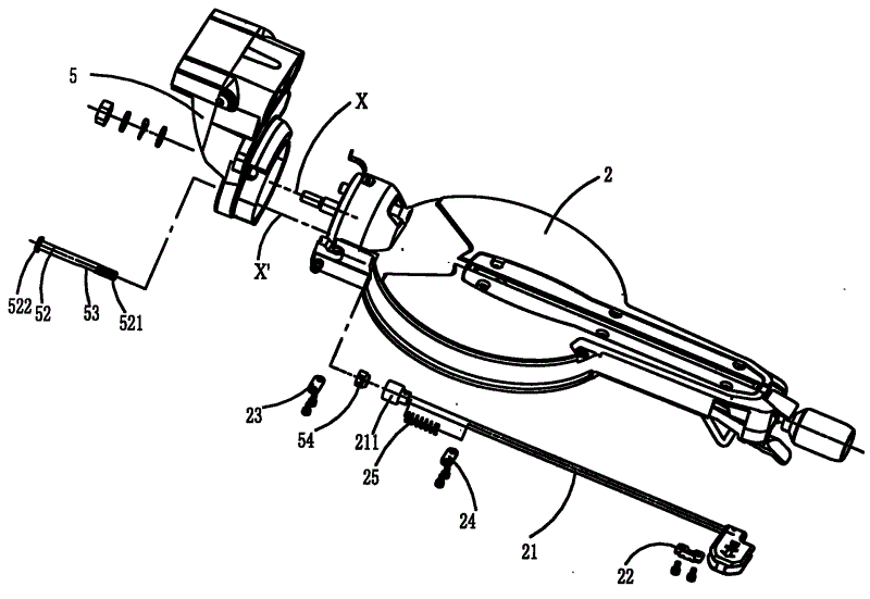
图2为图1中斜切锯的前置倾斜锁定机构的爆炸图;Fig. 2 is an exploded view of the front tilt locking mechanism of the miter saw in Fig. 1;
图3为图1中斜切锯前置倾斜锁定机构正常工作状态结构示意图;Fig. 3 is a structural schematic diagram of the normal working state of the front tilt locking mechanism of the miter saw in Fig. 1;
图4为图1中斜切锯的前置倾斜锁定机构手柄位置调节示意图;Fig. 4 is a schematic diagram of adjusting the position of the handle of the front tilt locking mechanism of the miter saw in Fig. 1;
图5为图4中A处放大图;Figure 5 is an enlarged view of A in Figure 4;
图6为图1中斜切锯的前置倾斜锁定机构手柄立体图。FIG. 6 is a perspective view of the handle of the front tilt locking mechanism of the miter saw in FIG. 1 .
具体实施方式Detailed ways
下面结合附图对本实用新型作进一步的说明。Below in conjunction with accompanying drawing, the utility model is further described.
参照图1,斜切锯10包含底座1、可转动地连接于底座1上的工作台2、绕一轴线X转动连接于工作台2的支撑臂5、滑动连接于支撑臂5的滑杆机构6,以及绕一轴线Y枢转连接于滑杆机构6上的锯装置3,以及和底座1相连的靠栅装置4。在斜切锯的其他实施方式中,也可以不具备滑杆机构,而直接将锯装置枢转连接于支撑臂。锯装置3包含锯片30、为锯片提供动力的电机32,以及把手31。被加工件(图中未显示)可放置在工作台2上,并抵靠靠栅装置4。斜切锯10可通过将支撑有锯装置3的工作台2绕一轴线Z相对于底座转动来实现斜角切割、以及通过支撑臂5绕轴线X相对于工作台2转动实现斜边切割功能。轴线X、Y、Z两两垂直。本领域内的技术人员对以上功能和结构应该熟悉,此处不再赘述。Referring to FIG. 1 , a miter saw 10 includes a base 1 , a workbench 2 rotatably connected to the base 1 , a
下面结合图1-6详细说明倾斜锁定机构。倾斜锁定机构包含第一锁紧件52、第二锁紧件54、控制杆21。第一锁紧件52穿过支撑臂5上的一个弧形孔(图中未示出)、工作台2后部的沿轴线X′的孔(图中未示出),第一锁紧件52的末端521和第二锁紧件54配合,顶端堵头522靠在支撑臂5远离工作台的一侧。第二锁紧件54可绕着轴线X′相对于第一锁紧件52转动。轴线X′平行于轴线X。首选地,第一锁紧件52的末端521具有外螺纹,第二锁紧件54为六角螺母并具有和该末端521相配的内螺纹,通过绕轴线X′旋转第二锁紧件54使其在第一锁紧件52上沿轴线X′方向移动,调节第一锁紧件的顶端堵头522和第二锁紧件54之间的距离来相对于工作台2锁紧或者松开支撑臂5。第一、第二锁紧件上的螺纹首选是双线螺纹,以利于实现更快速的锁紧或松开。一固定在工作台底部的压板23压在第一锁紧件52上的具有一平面的部分53上以防止第一锁紧件52跟着第二锁紧件54绕轴线X′转动。The tilt locking mechanism will be described in detail below in conjunction with FIGS. 1-6 . The tilt locking mechanism includes a
控制杆21通过压板24装在工作台底部,可绕着轴线X′旋转,其一端设有一用于控制第二锁紧件54旋转的控制件211。控制件211首选为内十二角扳手,可套在第二锁紧件54上并带动其绕轴线X′转动。控制杆21另一端位于工作台2前部,其上设有一个沿轴线X′侧向延伸的手柄213以方便操作者操作控制杆。一回复弹簧25被设置在控制杆21和工作台底部之间,首选地回复弹簧25套在控制杆21上,其两端分别顶靠在控制件211和工作台底部构件上,并向控制杆21施力使其具有趋近第二锁紧件54的运动趋势。The
通过手柄213可拉动控制杆21沿着轴线X′移动到一第一位置和一第二位置。如图3所示,在第一位置上,在回复弹簧25弹力作用下,控制件211和第二锁紧件54接合,此时操作者可以通过手柄213操作控制杆21绕轴线X′转动来带动第二锁紧件54相对于第一锁紧件52转动,实现支撑臂5相对于工作台的锁紧或松开。如图4所示,当操作者通过手柄拉动控制杆21克服回复弹簧25的弹力作用沿着轴线X′移动到第二位置上,控制件211和第二锁紧件54脱离接合,此时操作者可以通过手柄213操作控制杆21绕轴线X′转动从而调节手柄213绕轴线X′的角度,这样操作者可以很方便地将手柄213调整到操作舒适的角度。控制杆21可与第二锁紧件54脱离的另一个好处是,当第一锁紧件52顶端堵头522和第二锁紧件54之间距离变大以至于在如图3所示第一位置上通过操作手柄旋转控制杆无法锁紧时,可将控制杆移动到第二位置使控制件和第二锁紧件脱离接合,然后操作手柄使控制杆带着控制件向松开方向转一定角度再使控制杆回复至第一位置使控制件和第二锁紧件接合,然后再向锁紧方向进一步旋转控制杆即可锁紧,这样操作者在斜切锯前部即可很方便地调节锁紧操作的行程。The
控制杆还可以软杆形式,只要其一端的控制件绕着轴线X′转动即可。软杆可以传递旋转运动,同时也可以传递直线方向的运动;优点就是可以改变锁紧手柄的位置和角度,不受锁紧位置的约束,结构的安排更容易,更适合操作。The control rod can also be in the form of a soft rod, as long as the control member at one end rotates around the axis X'. The soft rod can transmit rotational motion and linear motion at the same time; the advantage is that the position and angle of the locking handle can be changed without being restricted by the locking position, and the structure arrangement is easier and more suitable for operation.
以上已以较佳实施例公开了本实用新型,然其并非用以限制本实用新型,凡采用等同替换或者等效变换方式所获得的技术方案,均落在本实用新型的保护范围之内。The utility model has been disclosed above with preferred embodiments, but it is not intended to limit the utility model, and all technical solutions obtained by adopting equivalent replacement or equivalent transformation methods fall within the protection scope of the utility model.
Claims (9)
Priority Applications (4)
| Application Number | Priority Date | Filing Date | Title |
|---|---|---|---|
| CN2010202410953U CN201760668U (en) | 2010-06-28 | 2010-06-28 | miter saw |
| GB1110648.1A GB2481688A (en) | 2010-06-28 | 2011-06-23 | Mitre Saw with Front Inclination Locking Mechanism |
| DE201120050545 DE202011050545U1 (en) | 2010-06-28 | 2011-06-24 | Locking mechanism for a miter saw |
| US13/169,625 US20110314988A1 (en) | 2010-06-28 | 2011-06-27 | Locking mechanism for a miter saw |
Applications Claiming Priority (1)
| Application Number | Priority Date | Filing Date | Title |
|---|---|---|---|
| CN2010202410953U CN201760668U (en) | 2010-06-28 | 2010-06-28 | miter saw |
Publications (1)
| Publication Number | Publication Date |
|---|---|
| CN201760668U true CN201760668U (en) | 2011-03-16 |
Family
ID=43713271
Family Applications (1)
| Application Number | Title | Priority Date | Filing Date |
|---|---|---|---|
| CN2010202410953U Expired - Fee Related CN201760668U (en) | 2010-06-28 | 2010-06-28 | miter saw |
Country Status (4)
| Country | Link |
|---|---|
| US (1) | US20110314988A1 (en) |
| CN (1) | CN201760668U (en) |
| DE (1) | DE202011050545U1 (en) |
| GB (1) | GB2481688A (en) |
Cited By (4)
| Publication number | Priority date | Publication date | Assignee | Title |
|---|---|---|---|---|
| DE202011050545U1 (en) | 2010-06-28 | 2011-11-08 | Chervon (Hk) Limited | Locking mechanism for a miter saw |
| CN102632292A (en) * | 2012-04-09 | 2012-08-15 | 南京德朔实业有限公司 | Mitre saw |
| CN105149682A (en) * | 2015-10-10 | 2015-12-16 | 江苏苏美达五金工具有限公司 | miter saw |
| CN106414007A (en) * | 2013-12-16 | 2017-02-15 | 罗伯特·博世有限公司 | Miter saw including front accessible bevel lock system |
Families Citing this family (4)
| Publication number | Priority date | Publication date | Assignee | Title |
|---|---|---|---|---|
| CN105082262A (en) * | 2015-09-01 | 2015-11-25 | 嘉兴善拓机械有限公司 | Chain saw sleeve fixing structure |
| US9849605B2 (en) * | 2016-05-28 | 2017-12-26 | Chin-Chin Chang | Power miter saw having a fence with elevated platforms |
| US10434588B1 (en) * | 2018-03-23 | 2019-10-08 | Chin-Chin Chang | Mechanism for the relative positioning of an inclined member and a graduated member |
| TWI852535B (en) * | 2023-05-05 | 2024-08-11 | 力山工業股份有限公司 | Saw with a control handle having three-stage adjustment function |
Family Cites Families (12)
| Publication number | Priority date | Publication date | Assignee | Title |
|---|---|---|---|---|
| US2844173A (en) * | 1954-09-13 | 1958-07-22 | King Seely Corp | Arbor saw with single handle control of tilt and elevation |
| JPH0711921Y2 (en) * | 1989-08-30 | 1995-03-22 | リョービ株式会社 | Tool position setting device for workbench |
| JP3922476B2 (en) * | 1997-08-01 | 2007-05-30 | リョービ株式会社 | Tabletop cutting machine |
| US6513412B2 (en) * | 2001-01-09 | 2003-02-04 | Porter Cable Corp. | Adjustment mechanism |
| US6658977B2 (en) * | 2001-08-02 | 2003-12-09 | Lee-Cheng Chang | Locking mechanism for inclination adjustment of a blade of a cutting device |
| US7127977B2 (en) * | 2002-02-11 | 2006-10-31 | Porter-Cable/Delta | Remotely actuated beveling systems for a miter saw |
| US6662697B1 (en) * | 2002-05-24 | 2003-12-16 | Rexon Co., Ltd. | Circular saw having a saw arm angle adjusting device |
| US7311028B2 (en) * | 2002-06-25 | 2007-12-25 | Black & Decker Inc. | Front bevel indicator/front bevel lock |
| TW569908U (en) * | 2002-09-26 | 2004-01-01 | P & F Brother Ind Corp | Apparatus for adjusting and aligning slant cutting angle of cutting machine |
| JP4743472B2 (en) * | 2004-06-30 | 2011-08-10 | 日立工機株式会社 | Tabletop cutting machine |
| US7430949B2 (en) * | 2005-07-07 | 2008-10-07 | Rexon Co., Ltd. | Angle adjustment device for a pivot arm of a circular saw |
| CN201760668U (en) * | 2010-06-28 | 2011-03-16 | 南京德朔实业有限公司 | miter saw |
-
2010
- 2010-06-28 CN CN2010202410953U patent/CN201760668U/en not_active Expired - Fee Related
-
2011
- 2011-06-23 GB GB1110648.1A patent/GB2481688A/en not_active Withdrawn
- 2011-06-24 DE DE201120050545 patent/DE202011050545U1/en not_active Expired - Lifetime
- 2011-06-27 US US13/169,625 patent/US20110314988A1/en not_active Abandoned
Cited By (7)
| Publication number | Priority date | Publication date | Assignee | Title |
|---|---|---|---|---|
| DE202011050545U1 (en) | 2010-06-28 | 2011-11-08 | Chervon (Hk) Limited | Locking mechanism for a miter saw |
| GB2481688A (en) * | 2010-06-28 | 2012-01-04 | Chervon Hk Ltd | Mitre Saw with Front Inclination Locking Mechanism |
| CN102632292A (en) * | 2012-04-09 | 2012-08-15 | 南京德朔实业有限公司 | Mitre saw |
| CN102632292B (en) * | 2012-04-09 | 2014-07-30 | 南京德朔实业有限公司 | Mitre saw |
| CN106414007A (en) * | 2013-12-16 | 2017-02-15 | 罗伯特·博世有限公司 | Miter saw including front accessible bevel lock system |
| CN106414007B (en) * | 2013-12-16 | 2020-03-24 | 罗伯特·博世有限公司 | Miter saw including front accessible tilt lock system |
| CN105149682A (en) * | 2015-10-10 | 2015-12-16 | 江苏苏美达五金工具有限公司 | miter saw |
Also Published As
| Publication number | Publication date |
|---|---|
| GB201110648D0 (en) | 2011-08-10 |
| US20110314988A1 (en) | 2011-12-29 |
| GB2481688A (en) | 2012-01-04 |
| DE202011050545U1 (en) | 2011-11-08 |
Similar Documents
| Publication | Publication Date | Title |
|---|---|---|
| CN201760668U (en) | miter saw | |
| US7854187B2 (en) | Rotary worktable positioning structure for miter saw | |
| US9216485B2 (en) | Quick clamping device adapted for worktable | |
| US20110237166A1 (en) | Bed-type circular saw blade grinder | |
| US20080276767A1 (en) | Pliers that Can Operate Workpieces of Two Different Types | |
| CN206653320U (en) | Adjustable ratchet wrench | |
| US20100018372A1 (en) | Adjustable fence assembly for a miter saw | |
| GB2441869A (en) | Band saw machine with actuating shaft for replacing saw blade | |
| TWI471208B (en) | A pipe cutter | |
| CN204975530U (en) | Adjustable fast double -layered device suitable for cutting means | |
| CN102000878B (en) | Diagonal cutting saw | |
| WO2012146214A1 (en) | Oblique cutting saw | |
| CN2762927Y (en) | Bottom plate adjusting device for sweep-saw | |
| CN218018220U (en) | Wrench for pipe cutting machine | |
| CN202556104U (en) | Fast clamping device applicable to worktable board | |
| TWI593532B (en) | Workpiece supporting apparatus for tile cutter | |
| CA2697493C (en) | Bed-type circular saw blade grinder | |
| CN201579730U (en) | chain wrench | |
| CN2487500Y (en) | Improved Grinding Head Fixing Structure | |
| CN211638569U (en) | Installation structure of tapping device and tapping machine | |
| CN203485150U (en) | Handheld machine tool and base plate adjusting mechanism for same | |
| CN117283455B (en) | Double-mounting-plate blade handheld polishing clamp and polishing method | |
| CN104440797B (en) | Hand held power machine and the bottom plate adjusting mechanism for this hand held power machine | |
| CN204149260U (en) | The quick positioning locking mechanism of crosscut guiding ruler | |
| CN203738143U (en) | Vice clamp tool used for table circular sawing machine |
Legal Events
| Date | Code | Title | Description |
|---|---|---|---|
| C14 | Grant of patent or utility model | ||
| GR01 | Patent grant | ||
| CF01 | Termination of patent right due to non-payment of annual fee | ||
| CF01 | Termination of patent right due to non-payment of annual fee |
Granted publication date: 20110316 Termination date: 20180628 |