CN201772434U - Remote system for monitoring operation energy efficiency index of boiler - Google Patents
Remote system for monitoring operation energy efficiency index of boiler Download PDFInfo
- Publication number
- CN201772434U CN201772434U CN2010205132574U CN201020513257U CN201772434U CN 201772434 U CN201772434 U CN 201772434U CN 2010205132574 U CN2010205132574 U CN 2010205132574U CN 201020513257 U CN201020513257 U CN 201020513257U CN 201772434 U CN201772434 U CN 201772434U
- Authority
- CN
- China
- Prior art keywords
- boiler
- data
- monitoring
- monitor
- energy efficiency
- Prior art date
- Legal status (The legal status is an assumption and is not a legal conclusion. Google has not performed a legal analysis and makes no representation as to the accuracy of the status listed.)
- Expired - Fee Related
Links
Images

Classifications
-
- Y02B60/50—
Landscapes
- Regulation And Control Of Combustion (AREA)
Abstract
Description
技术领域technical field
本实用新型涉及一种锅炉运行能效指标远程监测系统。The utility model relates to a remote monitoring system for boiler operation energy efficiency indicators.
背景技术Background technique
锅炉作为我国主要的耗能设备每年消耗全国原煤产量的约三分之二,其能效状况直接影响到工业锅炉耗能的大小,全球能源紧缺的现况更是让人们越来越认识到提高锅炉能效水平对节约能源的重要性。目前,锅炉能效状况受到重视的同时,对其运行能效水平的监测也已成为一种必然趋势,为了有效监控高耗能锅炉的使用情况,防止锅炉运行过程中出现不符合相关要求的高耗能工况,有必要为锅炉能效监管部门研制专用的远程监测系统。Boilers, as the main energy-consuming equipment in my country, consume about two-thirds of the country's raw coal production every year, and their energy efficiency directly affects the energy consumption of industrial boilers. The importance of energy efficiency levels to save energy. At present, while the energy efficiency of boilers is paid attention to, the monitoring of their energy efficiency level has become an inevitable trend. In order to effectively monitor the use of high-energy-consuming boilers and prevent high-energy-consuming Working conditions, it is necessary to develop a dedicated remote monitoring system for the boiler energy efficiency supervision department.
发明内容Contents of the invention
本实用新型的目的就是提供一种系统设备简单、成本低、维护方便,可以实时对锅炉运行能效状况进行监督,有效防止锅炉超标高耗能运行的锅炉运行能效指标远程监测系统。The purpose of this utility model is to provide a remote monitoring system for boiler operation energy efficiency indicators with simple system equipment, low cost and convenient maintenance, which can monitor the energy efficiency of the boiler operation in real time and effectively prevent the boiler from exceeding the standard and high energy consumption.
本实用新型的锅炉运行能效指标远程监测系统,包括监测站、中央控制柜及监测设备,中央控制柜包括数据发送单元、中央处理单元、数据储存单元和供电保护单元,监测设备包括炉渣含碳量自动分析仪、饱和蒸汽湿度监测器、排烟温度采集器、奥氏分析仪或燃烧效率测试仪探头、飞灰含碳量监测仪,炉渣含碳量自动分析仪安装在锅炉除渣器中,锅炉主蒸汽管道中布置饱和蒸汽湿度监测器,排烟温度采集器、飞灰含碳量监测仪、奥氏分析仪或燃烧效率测试仪探头布置在锅炉最后一级尾部受热面出口的平直烟道中心处,监测设备定时采集数据并通过数据传输线接入到中央控制柜的端口将数据传输到中央处理器中进行处理,中央处理器将接收到的数据先进行数据存储后将数据与预设参数进行对比,预设参数采用现行锅炉能效监测指标,对于未达到预设参数标准的数据,中央处理器会将这组数据传输给发送装置,发送装置将以GPRS或短信方式通过GPRS网/GSM网发送至监测站,监测站的接收装置接收到监测数据后将数据经传输线输送至监测终端。The boiler operation energy efficiency index remote monitoring system of the utility model includes a monitoring station, a central control cabinet and monitoring equipment, the central control cabinet includes a data sending unit, a central processing unit, a data storage unit and a power supply protection unit, and the monitoring equipment includes a carbon content of slag Automatic analyzer, saturated steam humidity monitor, exhaust gas temperature collector, Austenitic analyzer or combustion efficiency tester probe, fly ash carbon content monitor, slag carbon content automatic analyzer installed in the boiler slag remover, The saturated steam humidity monitor is arranged in the main steam pipe of the boiler, and the exhaust gas temperature collector, fly ash carbon content monitor, Austenitic analyzer or combustion efficiency tester probe is arranged in the straight smoke at the outlet of the heating surface of the last stage of the boiler. At the center of the road, the monitoring equipment regularly collects data and connects to the port of the central control cabinet through the data transmission line to transmit the data to the central processor for processing. The central processor first stores the received data and then compares the data with the preset The parameters are compared, and the preset parameters adopt the current boiler energy efficiency monitoring indicators. For the data that does not meet the preset parameter standards, the central processing unit will transmit this set of data to the sending device, and the sending device will pass GPRS network/GSM in the form of GPRS or SMS After receiving the monitoring data, the receiving device of the monitoring station transmits the data to the monitoring terminal through the transmission line.
本实用新型的锅炉运行能效指标远程监测系统,可以实时对锅炉运行能效状况进行监督,有效防止锅炉超标高耗能运行,系统设备简单、成本低、维护容易,且监测数据采用短信和GPRS两种方式发送,如果一种方式传输失败则自动采用另一种方式传输数据,可以保证数据的有效传输,该系统能够对锅炉能效水平进行实时记录、对于超标运行锅炉能够即时向锅炉能效监管部门发送超标运行数据。The boiler operation energy efficiency index remote monitoring system of the utility model can monitor the energy efficiency status of the boiler operation in real time, effectively prevent the boiler from exceeding the standard high energy consumption operation, the system equipment is simple, the cost is low, and the maintenance is easy, and the monitoring data adopts SMS and GPRS. If one method fails to transmit data, another method will be used to transmit data automatically, which can ensure the effective transmission of data. The system can record the energy efficiency level of the boiler in real time. Operating data.
附图说明Description of drawings
图1为本实用新型系统结构示意图;Fig. 1 is a schematic structural diagram of the utility model system;
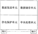
图2为本实用新型的中央控制柜单元结构示意图。Fig. 2 is a structural schematic diagram of the central control cabinet unit of the present invention.
具体实施方式Detailed ways
一种锅炉运行能效指标远程监测系统,包括监测站1、中央控制柜2及监测设备3,中央控制柜2包括数据发送单元、中央处理单元、数据储存单元和供电保护单元,监测设备3包括炉渣含碳量自动分析仪、饱和蒸汽湿度监测器、排烟温度采集器、奥氏分析仪或燃烧效率测试仪探头、飞灰含碳量监测仪。锅炉除渣器中布置炉渣含碳量自动分析仪,该分析仪每15min自动采集一次试样并进行分析,同时将分析结果经输出端传输至中央控制柜2;锅炉主蒸汽管道中布置饱和蒸汽湿度监测器,用于监测饱和蒸汽湿度;锅炉最后一级尾部受热面出口1m以内的平直烟道布置排烟温度采集器,该采集器用于监测锅炉排烟温度,采集的数据可以经输出端传输至中央控制柜2;锅炉最后一级尾部受热面出口1m以内的平直烟道内还布置了飞灰含碳量监测仪、奥氏分析仪或燃烧效率测试仪探头,测点采集数据并将传输至中央控制柜2,中央处理器会取平均数据作为一次监测数据,上述所有测点均每15min采集一次数据并传输至中央控制柜。A remote monitoring system for energy efficiency indicators of boiler operation, comprising a monitoring station 1, a
监测设备3布置于锅炉中各监测点上定时采集数据并通过数据传输线接入到中央控制柜2的端口将数据传输到中央处理器中进行处理,中央处理器将接收到的数据先进行数据存储后将数据与预设参数进行对比,预设参数采用现行锅炉能效监测指标,对于未达到预设参数标准的数据,中央处理器会将这组数据传输给发送装置,发送装置将以GPRS或CDMA方式通过GPRS网/GSM网发送至监测站,监测站的接收装置接收到监测数据后将数据经传输线输送至监测终端。The
中央控制柜有以下几个基本硬件单元组成:多个数据传输端口,用于连接监测设备以及将储存数据对外输出;中央处理单元,用于监测数据的采集、采集数据与预设参数的比较、控制数据发送及数据经端口对外输出等;供电保护单元,负责控制柜的供电保护;数据发送单元,负责发送GPRS数据或CDMA;数据存储单元,负责保存监测数据。The central control cabinet consists of the following basic hardware units: multiple data transmission ports, used to connect monitoring equipment and output stored data to the outside; central processing unit, used to collect monitoring data, compare the collected data with preset parameters, Control data transmission and data output through ports, etc.; power supply protection unit, responsible for power supply protection of the control cabinet; data transmission unit, responsible for sending GPRS data or CDMA; data storage unit, responsible for saving monitoring data.
Claims (1)
Priority Applications (1)
| Application Number | Priority Date | Filing Date | Title |
|---|---|---|---|
| CN2010205132574U CN201772434U (en) | 2010-09-01 | 2010-09-01 | Remote system for monitoring operation energy efficiency index of boiler |
Applications Claiming Priority (1)
| Application Number | Priority Date | Filing Date | Title |
|---|---|---|---|
| CN2010205132574U CN201772434U (en) | 2010-09-01 | 2010-09-01 | Remote system for monitoring operation energy efficiency index of boiler |
Publications (1)
| Publication Number | Publication Date |
|---|---|
| CN201772434U true CN201772434U (en) | 2011-03-23 |
Family
ID=43752280
Family Applications (1)
| Application Number | Title | Priority Date | Filing Date |
|---|---|---|---|
| CN2010205132574U Expired - Fee Related CN201772434U (en) | 2010-09-01 | 2010-09-01 | Remote system for monitoring operation energy efficiency index of boiler |
Country Status (1)
| Country | Link |
|---|---|
| CN (1) | CN201772434U (en) |
Cited By (2)
| Publication number | Priority date | Publication date | Assignee | Title |
|---|---|---|---|---|
| CN102385370A (en) * | 2011-09-30 | 2012-03-21 | 东南大学 | System and method for monitoring energy efficiency of economical coal-fired boiler |
| CN113218681A (en) * | 2020-12-30 | 2021-08-06 | 新奥数能科技有限公司 | Solid fuel industrial boiler monitoring system and boiler thermal efficiency monitoring method |
-
2010
- 2010-09-01 CN CN2010205132574U patent/CN201772434U/en not_active Expired - Fee Related
Cited By (4)
| Publication number | Priority date | Publication date | Assignee | Title |
|---|---|---|---|---|
| CN102385370A (en) * | 2011-09-30 | 2012-03-21 | 东南大学 | System and method for monitoring energy efficiency of economical coal-fired boiler |
| CN102385370B (en) * | 2011-09-30 | 2013-05-08 | 东南大学 | System and method for monitoring energy efficiency of economical coal-fired boiler |
| CN113218681A (en) * | 2020-12-30 | 2021-08-06 | 新奥数能科技有限公司 | Solid fuel industrial boiler monitoring system and boiler thermal efficiency monitoring method |
| CN113218681B (en) * | 2020-12-30 | 2023-05-12 | 新奥数能科技有限公司 | Solid fuel industrial boiler monitoring system and boiler thermal efficiency monitoring method |
Similar Documents
| Publication | Publication Date | Title |
|---|---|---|
| CN102568172A (en) | System for remotely carrying out on-line monitoring on discharge concentration of waste gas dust discharged by desulfurizer | |
| CN102734782A (en) | Coal burning boiler energy efficiency monitoring method | |
| CN202470022U (en) | Remote online monitoring device for industrial coal boiler | |
| CN201936436U (en) | Desulphurization device waste-gas soot-dust emission concentration remote on-line monitoring system | |
| CN104750098A (en) | Internet of things monitoring and diagnosis disposal system for universal boiler | |
| CN103149043A (en) | Real-time monitoring system and monitoring method of heat efficiency of condensing gas boiler | |
| CN102944536A (en) | Oil fume detection system based on sensor network and multi-source information fusion | |
| CN102193548A (en) | Real-time monitoring system for pollutant discharging and purifying device | |
| CN203415084U (en) | Remote monitoring system for heating boilers based on GPRS communication technology | |
| CN109611813A (en) | A kind of boiler efficiency on-line monitoring method and system | |
| CN103323273A (en) | Method for detecting performance of power station boiler air pre-heater | |
| CN111522323A (en) | Boiler energy efficiency online diagnosis and intelligent control method based on Internet of things technology | |
| CN106765029A (en) | Complex data collecting device is sensed a kind of boiler based on Internet of Things more | |
| CN209215278U (en) | Gas industry boiler smoke on-line analysis system | |
| CN216647163U (en) | A natural gas management device based on remote monitoring | |
| CN207337155U (en) | Kitchen fumes discharge big data monitor supervision platform framework based on NB-iot networks | |
| CN206468519U (en) | A kind of air compressor efficiency on-line checking assessment system | |
| CN204903492U (en) | Waste gas detector | |
| CN111443168A (en) | A boiler flue gas nitrogen oxide monitoring and alarm system | |
| CN205210605U (en) | Harmful gas data collection station and monitoring system who constitutes thereof | |
| CN201984323U (en) | Wireless remote multi-stage independent thermal power plant desulfurization process monitoring and management system | |
| CN204535749U (en) | A kind of universal boiler Internet of Things monitor signal acquisition system based on PLC | |
| CN115750013A (en) | Real-time calculation system for carbon emission flow of power system | |
| CN205067455U (en) | Nitrogen element morphological analysis monitoring devices | |
| CN205537770U (en) | Underground piping monitor terminal |
Legal Events
| Date | Code | Title | Description |
|---|---|---|---|
| C14 | Grant of patent or utility model | ||
| GR01 | Patent grant | ||
| C17 | Cessation of patent right | ||
| CF01 | Termination of patent right due to non-payment of annual fee |
Granted publication date: 20110323 Termination date: 20110901 |