CN201775843U - Press-type drug mist generating device for medical use and its press mechanism - Google Patents
Press-type drug mist generating device for medical use and its press mechanism Download PDFInfo
- Publication number
- CN201775843U CN201775843U CN2010201792541U CN201020179254U CN201775843U CN 201775843 U CN201775843 U CN 201775843U CN 2010201792541 U CN2010201792541 U CN 2010201792541U CN 201020179254 U CN201020179254 U CN 201020179254U CN 201775843 U CN201775843 U CN 201775843U
- Authority
- CN
- China
- Prior art keywords
- generating device
- relief hole
- compressed gas
- mist generating
- arm
- Prior art date
- Legal status (The legal status is an assumption and is not a legal conclusion. Google has not performed a legal analysis and makes no representation as to the accuracy of the status listed.)
- Expired - Lifetime
Links
- 239000003814 drug Substances 0.000 title claims abstract description 117
- 239000003595 mist Substances 0.000 title claims description 67
- 229940079593 drug Drugs 0.000 title claims description 40
- 238000003825 pressing Methods 0.000 claims abstract description 50
- 239000007921 spray Substances 0.000 claims description 15
- 239000000463 material Substances 0.000 claims description 12
- 239000012530 fluid Substances 0.000 claims description 9
- 238000007789 sealing Methods 0.000 claims description 3
- 238000007599 discharging Methods 0.000 claims 2
- 238000003860 storage Methods 0.000 abstract description 14
- 238000005507 spraying Methods 0.000 abstract description 7
- 239000002699 waste material Substances 0.000 abstract description 7
- 230000007721 medicinal effect Effects 0.000 abstract description 5
- 238000004519 manufacturing process Methods 0.000 abstract description 4
- 239000007789 gas Substances 0.000 description 84
- 239000007788 liquid Substances 0.000 description 4
- 238000000034 method Methods 0.000 description 4
- 241000894006 Bacteria Species 0.000 description 3
- 238000010586 diagram Methods 0.000 description 3
- 230000000694 effects Effects 0.000 description 3
- 210000004072 lung Anatomy 0.000 description 3
- 241000700605 Viruses Species 0.000 description 2
- 201000010099 disease Diseases 0.000 description 2
- 208000037265 diseases, disorders, signs and symptoms Diseases 0.000 description 2
- 238000012377 drug delivery Methods 0.000 description 2
- 238000001914 filtration Methods 0.000 description 2
- 230000003434 inspiratory effect Effects 0.000 description 2
- 229940126701 oral medication Drugs 0.000 description 2
- 230000002093 peripheral effect Effects 0.000 description 2
- 210000002345 respiratory system Anatomy 0.000 description 2
- 238000003892 spreading Methods 0.000 description 2
- 239000013589 supplement Substances 0.000 description 2
- MYMOFIZGZYHOMD-UHFFFAOYSA-N Dioxygen Chemical compound O=O MYMOFIZGZYHOMD-UHFFFAOYSA-N 0.000 description 1
- 238000010521 absorption reaction Methods 0.000 description 1
- 230000000903 blocking effect Effects 0.000 description 1
- 238000007664 blowing Methods 0.000 description 1
- 210000000621 bronchi Anatomy 0.000 description 1
- 239000002131 composite material Substances 0.000 description 1
- 230000006835 compression Effects 0.000 description 1
- 238000007906 compression Methods 0.000 description 1
- 230000008034 disappearance Effects 0.000 description 1
- 210000001035 gastrointestinal tract Anatomy 0.000 description 1
- 238000002663 nebulization Methods 0.000 description 1
- 239000006199 nebulizer Substances 0.000 description 1
- 230000000149 penetrating effect Effects 0.000 description 1
- 239000002912 waste gas Substances 0.000 description 1
Images




Landscapes
- Nozzles (AREA)
Abstract
Description
技术领域technical field
本实用新型涉及一种给药装置,尤其涉及一种医疗用按压式药雾产生装置及其按压机构。The utility model relates to a drug delivery device, in particular to a medical pressing type drug mist generating device and a pressing mechanism thereof.
背景技术Background technique
人类的疾病70%以上与环境有关,而环境对人类的呼吸系统影响最大,将药物投递于病人以治疗呼吸道疾病的途径,最有效、普遍、且病人接受度最高的方法为,将口服药物经口递送,但药物容易在消化道被分解掉,所以开发出经口、鼻、肺递送的投药途径,其为喷雾治疗方法,以雾化器(nebulizer)制造出药雾供病人吸入,药雾直接进入支气管,再扩散至整个肺泡,效果比一般口服式的药物有效率及直接。More than 70% of human diseases are related to the environment, and the environment has the greatest impact on the human respiratory system. The most effective, common and most acceptable way to deliver drugs to patients is to deliver oral drugs through Oral delivery, but the drug is easily broken down in the digestive tract, so the drug delivery route through the mouth, nose, and lungs has been developed. Directly enter the bronchi, and then diffuse to the entire alveoli, the effect is more efficient and direct than ordinary oral drugs.
现有的雾化器,包含一筒身、连通于筒身底部的一制雾结构、连通于筒身顶部的一“T”型管、和分别连通于“T”型管两端的一套管及一缓冲管,筒内预置药液并由制雾结构将之雾化,缓冲管的自由端为开放空间,病人咬夹套管并吸取药雾。The existing atomizer consists of a cylinder body, a mist-making structure connected to the bottom of the cylinder body, a "T"-shaped tube connected to the top of the cylinder body, and sleeves respectively connected to both ends of the "T"-shaped tube And a buffer tube, the medicine liquid is preset in the tube and atomized by the mist making structure, the free end of the buffer tube is an open space, the patient bites the jacket tube and absorbs the medicine mist.
当病人吸气时,药雾从筒身内经由“T”型管、套管而进入呼吸道,并经由缓冲管吸入外界空气以补足病人的吸气量。When the patient inhales, the drug mist enters the respiratory tract from the cylinder body through the "T" tube and the cannula, and inhales the outside air through the buffer tube to supplement the patient's inhalation volume.
当病人停止吸气时,雾化器仍持续制造药雾,并从缓冲管散逸散至外界,或当病人呼气时,废气经由套管、缓冲管排放至外界,却也一并将药雾吹离,造成浪费并污染环境,而令筒内预置的药液量实际使用效率不佳,若要达到必须的疗程,需增加预置药液量,因而提高医疗费用。When the patient stops inhaling, the nebulizer still continues to produce the drug mist, and dissipates from the buffer tube to the outside, or when the patient exhales, the exhaust gas is discharged to the outside through the sleeve and the buffer tube, but the drug mist is also released. Blowing away causes waste and pollutes the environment, and the actual use efficiency of the amount of liquid medicine preset in the barrel is not good. If a necessary course of treatment is to be achieved, the amount of liquid medicine preset must be increased, thereby increasing medical expenses.
实用新型内容Utility model content
本实用新型的一目的,在于提供一种药雾产生装置的按压机构,可依据使用者的需求情况,驱动装置以制造或停制药雾,能降低药剂浪费并提升用药效率及医疗效果。An object of the present invention is to provide a pressing mechanism of a medicine mist generating device, which can drive the device to produce or stop medicine mist according to the needs of users, which can reduce medicine waste and improve medicine efficiency and medical effect.
为了达到上述的目的,本实用新型提供一种药雾产生装置的按压机构,所述装置具有一储药容器及装设在所述储药容器的一喷雾结构,所述喷雾结构具有一压缩气体通道,该按压机构包括:In order to achieve the above object, the utility model provides a pressing mechanism of a drug mist generating device, the device has a drug storage container and a spray structure installed in the drug storage container, the spray structure has a compressed gas channel, the pressing mechanism consists of:
一筒座,具有插接所述压缩气体通道且供压缩气体流通的一输气管、及连通该输气管的一泄压孔,在该泄压孔侧的该筒座外周成型有一枢部;以及A cylinder seat, having a gas delivery pipe inserted into the compressed gas channel and for the compressed gas to circulate, and a pressure relief hole communicating with the gas delivery pipe, a hub is formed on the outer periphery of the cylinder seat at the side of the pressure relief hole; and
一按压组件,包含枢接在该枢部的一扳臂、自该扳臂延伸且对应该泄压孔位置配设的一阀门、及连接于该扳臂且抵贴于所述储药容器的一弹性臂;A pressing assembly, including a trigger arm pivotally connected to the pivot, a valve extending from the trigger arm and corresponding to the position of the pressure relief hole, and a valve connected to the trigger arm and abutted against the drug storage container an elastic arm;
其中,扳动该扳臂作转动时,该阀门将封闭该泄压孔以使所述压缩气体流经该输气管再进入所述压缩气体通道中;反之,释放该扳臂时受该弹性臂的弹性抵推而令该阀门与该泄压孔脱离密封,以使所述压缩气体流经该输气管而从该泄压孔流出。Wherein, when the trigger arm is pulled to rotate, the valve will close the pressure relief hole so that the compressed gas flows through the air pipe and then enters the compressed gas channel; The elastic resistance of the valve makes the valve and the pressure relief hole unsealed, so that the compressed gas flows through the air pipe and flows out of the pressure relief hole.
上述的药雾产生装置的按压机构,其中,于该扳臂成型有压制该弹性臂外周的一压制杆。In the above-mentioned pressing mechanism of the medicine mist generating device, a pressing rod that presses the outer periphery of the elastic arm is molded on the trigger arm.
上述的药雾产生装置的按压机构,其中,该泄压孔的孔径中心线与该输气管的管道轴心线相互正交。In the above-mentioned pressing mechanism of the medicinal mist generating device, the center line of the pressure relief hole and the axis line of the air pipe are perpendicular to each other.
本实用新型的另一目的,在于提供一种医疗用按压式药雾产生装置,可依据使用者的需求情况,驱动装置以制造或停制药雾,能降低药剂浪费并提升用药效率及医疗效果。Another purpose of the present utility model is to provide a press-type drug mist generating device for medical use, which can drive the device to produce or stop the drug mist according to the user's needs, which can reduce the waste of medicine and improve the efficiency of drug use and medical effect.
为了达到上述的目的,本实用新型还提供一种医疗用按压式药雾产生装置,该医疗用按压式药雾产生装置,包括:In order to achieve the above purpose, the utility model also provides a medical push-type drug mist generating device, which includes:
一储药容器,具有用以储存药剂的一腔室;A medicine storage container has a chamber for storing medicine;
一喷雾结构,装设在该储药容器,具有连通该腔室的一压缩气体通道;以及a spray structure, installed in the drug storage container, has a compressed gas channel communicating with the chamber; and
一按压机构,包含:A pressing mechanism, comprising:
一筒座,具有插接该压缩气体通道且供压缩气体流通的一输气管、及连通该输气管的一泄压孔,在该泄压孔侧的该筒座外周成型有一枢部;以及A cylinder seat, having a gas delivery pipe inserted into the compressed gas channel and for the compressed gas to circulate, and a pressure relief hole communicating with the gas delivery pipe, a hub is formed on the outer periphery of the cylinder seat at the side of the pressure relief hole; and
一按压组件,包含枢接在该枢部的一扳臂、自该扳臂延伸且对应该泄压孔位置配设的一阀门、及连接于该扳臂且抵贴于所述储药容器的一弹性臂;A pressing assembly, including a trigger arm pivotally connected to the pivot, a valve extending from the trigger arm and corresponding to the position of the pressure relief hole, and a valve connected to the trigger arm and abutted against the drug storage container an elastic arm;
其中,扳动该扳臂作转动时,该阀门将封闭该泄压孔以使所述压缩气体流经该输气管再进入所述压缩气体通道中,令喷雾结构对储存在该腔室中的所述药剂进行雾化,反之,释放该扳臂时受该弹性臂的弹性抵推而令该阀门与该泄压孔脱离密封,以使所述压缩气体流经该输气管而从该泄压孔流出,令所述药剂停止雾化。Wherein, when the trigger arm is pulled to rotate, the valve will close the pressure relief hole so that the compressed gas flows through the gas delivery pipe and then enters the compressed gas passage, so that the spraying structure is relatively sensitive to the gas stored in the chamber. The medicament is atomized, and on the contrary, when the trigger arm is released, it is pushed by the elasticity of the elastic arm, so that the valve and the pressure relief hole are separated from the seal, so that the compressed gas flows through the air tube to release the pressure. The holes flow out, stopping the nebulization of the medicament.
上述的医疗用按压式药雾产生装置,其中,该储药容器包含具有该腔室的一筒身、及连接于该筒身一端的一罩体。In the aforementioned press-type drug mist generating device for medical use, the drug storage container includes a cylinder body having the cavity, and a cover connected to one end of the cylinder body.
上述的医疗用按压式药雾产生装置,其中,该罩体包含一下盖,该下盖具有彼此独立的一进气通道及一排气通道。In the above-mentioned push-type medicinal mist generating device for medical use, the cover body includes a lower cover, and the lower cover has an air inlet channel and an exhaust channel independent of each other.
上述的医疗用按压式药雾产生装置,其中,该筒身开设有连通该腔室的一混合气体出口,该进气通道对应该腔室配置,该排气通道对应该混合气体出口配置。In the above-mentioned press-type medicinal mist generating device for medical use, the cylinder body is provided with a mixed gas outlet communicating with the chamber, the air inlet channel is arranged corresponding to the chamber, and the exhaust channel is arranged corresponding to the mixed gas outlet.
上述的医疗用按压式药雾产生装置,其中,该下盖与该筒身之间形成有连通该腔室及该混合气体出口的一混合气体通道。In the aforementioned press-type medical mist generating device for medical use, a mixed gas channel communicating with the chamber and the mixed gas outlet is formed between the lower cover and the cylinder body.
上述的医疗用按压式药雾产生装置,其中,该下盖开设有连通该进气通道的一进气孔、及连通该排气通道的一排气孔,且该下盖包含对应进气孔作启闭而跨设于进气通道的一单向进气阀、及对应排气孔作启闭而跨设于排气通道的一单向排气阀。In the above-mentioned press-type medicinal mist generating device for medical use, the lower cover is provided with an air intake hole communicating with the air intake channel and an exhaust hole communicating with the exhaust channel, and the lower cover includes a corresponding air intake hole for opening A one-way intake valve is closed and straddled the intake passage, and a one-way exhaust valve is opened and closed corresponding to the exhaust hole and straddled the exhaust passage.
上述的医疗用按压式药雾产生装置,其中,该储药容器还包含用以滤封该排气孔而对应该排气孔设置的一滤材,该罩体还包含对应该排气孔配置而连接于该下盖的一上盖,该滤材装设于该上盖。In the above-mentioned press-type medicinal mist generating device for medical use, the medicine storage container further includes a filter material arranged corresponding to the vent hole for filtering and sealing the vent hole, and the cover body also includes a filter material corresponding to the vent hole. And an upper cover connected to the lower cover, the filter material is installed on the upper cover.
上述的医疗用按压式药雾产生装置,其中,该喷雾结构包含成型于该筒身的一锥柱,该压缩气体通道形成于该锥柱的凹陷侧,该锥柱开设有连通该腔室及该压缩气体通道的一压缩气体入口。In the above-mentioned press-type drug mist generating device for medical use, the spraying structure includes a conical column formed on the cylinder body, the compressed gas channel is formed on the concave side of the conical column, and the conical column is provided with a channel communicating with the chamber and A compressed gas inlet of the compressed gas channel.
上述的医疗用按压式药雾产生装置,其中,该泄压孔的孔径尺寸大于该压缩气体入口的孔径尺寸。In the aforementioned press-type drug mist generating device for medical use, the diameter of the pressure relief hole is larger than the diameter of the compressed gas inlet.
上述的医疗用按压式药雾产生装置,其中,该喷雾结构还包含设置于该锥柱周围的一锥形罩,该锥形罩与该锥柱之间形成有一流体通道。In the aforementioned press-type medical mist generating device for medical use, the spraying structure further includes a conical cover arranged around the conical column, and a fluid channel is formed between the conical cover and the conical column.
上述的医疗用按压式药雾产生装置,其中,该喷雾结构还包含对应该压缩气体入口及该流体通道设置的一挡块。In the aforementioned press-type medicinal mist generating device for medical use, the spraying structure further includes a stopper corresponding to the compressed gas inlet and the fluid channel.
上述的医疗用按压式药雾产生装置,其中,于该扳臂成型有压制该弹性臂外周的一压制杆。In the medical push-type drug mist generating device mentioned above, a pressing rod that presses the outer periphery of the elastic arm is molded on the trigger arm.
上述的医疗用按压式药雾产生装置,其中,该泄压孔的孔径中心线与该输气管的管道轴心线相互正交。In the aforementioned press-type drug mist generating device for medical use, the center line of the pressure relief hole and the axis line of the air pipe are perpendicular to each other.
相较于现有技术,本实用新型具有以下功效:Compared with the prior art, the utility model has the following effects:
可依据使用者的需求情况而制造或停制药雾,仅需持续扳动按压机构即能在储药容器中产生药雾,以供病患吸取药雾作治疗,当病患不需吸取药雾时,仅需释放按压机构即能令喷雾结构停止产生药雾,如此则能降低药剂浪费并提升用药效率及医疗效果。The medicine mist can be produced or stopped according to the needs of the user, and the medicine mist can be generated in the medicine storage container by continuously pulling the pressing mechanism for the patient to inhale the medicine mist for treatment. When the patient does not need to inhale the medicine mist When the device is in use, it is only necessary to release the pressing mechanism to stop the spray structure from producing the drug mist, which can reduce the waste of drugs and improve the efficiency of drug use and medical effect.
以下结合附图和具体实施例对本实用新型进行详细描述,但不作为对本实用新型的限定。The utility model will be described in detail below in conjunction with the accompanying drawings and specific embodiments, but not as a limitation of the utility model.
附图说明Description of drawings
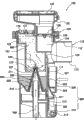
图1本实用新型的立体分解图;The three-dimensional exploded view of the utility model of Fig. 1;
图2本实用新型的立体组合图;Fig. 2 is the three-dimensional combined diagram of the utility model;
图3本实用新型的组合剖面图;The composite sectional view of Fig. 3 the utility model;
图4本实用新型的制造药雾图;Fig. 4 manufactures medicine mist figure of the utility model;
图5本实用新型的吸取药雾图;Fig. 5 is the drawing of medicine mist of the utility model;
图6本实用新型的呼气排放图;Fig. 6 is the expiratory discharge diagram of the utility model;
图7本实用新型的停制药雾图。Fig. 7 is the spray diagram of stopping medicine of the utility model.
其中,附图标记Among them, reference signs
储药容器100
筒身110
腔室111
混合气体出口112Mixed
凸管113Convex
罩体120
下盖121
上盖122
进气通道123Intake
排气通道124
进气孔125
排气孔126
单向进气阀127One-
单向排气阀128One-
混合气体通道129
滤材130
喷雾结构200
锥柱210
压缩气体通道211
压缩气体入口212
锥形罩220
流体通道221
挡块230
按压机构300
筒座310
输气管311
泄压孔312
枢部313
按压组件320
扳臂321
阀门322
弹性臂323
压制杆324
药剂400
压缩气体500
药雾600
具体实施方式Detailed ways
有关本实用新型的详细说明及技术内容,将配合图式说明如下,然而所附图式仅作为说明用途,并非用于局限本实用新型。The detailed description and technical content of the present utility model will be described as follows with accompanying drawings, but the attached drawings are only for illustration purposes and are not intended to limit the present utility model.
本实用新型涉及一种药雾产生装置的按压机构、及医疗用按压式药雾产生装置,请参照图1至图3所示,装置包括一储药容器100、一喷雾结构200、及一按压机构300。The utility model relates to a pressing mechanism of a drug mist generating device and a pressing type drug mist generating device for medical use. Please refer to FIGS.
储药容器100包含一筒身110、一罩体120、及一滤材130。The
筒身110呈圆筒状,但不以此形状为限,其尺寸大小、形状设计以适合人体的手部握持为较佳,筒身110内部具有一腔室111,腔室111并贯通筒身110的顶端。The
筒身110的外周壁上部开设有一混合气体出口112,混合气体出口112并连通腔室111,又混合气体出口112周缘径向凸起成型有一凸管113,凸管113呈中空状且连通混合气体出口112。The upper part of the outer peripheral wall of the
罩体120嵌置入腔室111上部空间并封合筒身110的顶端,罩体120包含一下盖121及与下盖121相互组合的一上盖122。The
下盖121内部具有彼此独立的一进气通道123及一排气通道124,进气通道123对应腔室111配置,排气通道124对应混合气体出口112配置,且下盖121的顶面开设有连通进气通道123的一进气孔125、及连通排气通道124的一排气孔126。The inside of the
又,下盖121包含对应进气孔125作启闭而跨设于进气通道123的一单向进气阀127、及对应排气孔126作启闭而跨设于排气通道124的一单向排气阀128,另外,下盖121与混合气体出口112侧的筒身110内壁之间形成有一混合气体通道129,混合气体通道129连通腔室111及混合气体出口112。Also, the
上盖122对应排气孔126配置而连接于下盖121的顶面,滤材130则装设于上盖122,滤材130用以滤封排气孔126,上盖122及滤材130为附加性功能的对象,其针对病人呼出的气体做滤菌使用,可因应使用需求作加装。The
喷雾结构200嵌置于筒身110的底端,药雾产生器200以卡接方式与筒身110固定连接,但不以此种连接手段为限。The
喷雾结构200包含一锥柱210、一锥形罩220、及一挡块230。The
锥柱210由筒身110的内底壁向腔室111冲压成型,于锥柱210的凹陷侧形成有一压缩气体通道211,锥柱210的顶端开设有连通腔室111及压缩气体通道211的一压缩气体入口212。The
锥形罩220呈贯穿状,锥形罩220设置于锥柱210的凸起侧外周围,又锥形罩220与锥柱210之间相互间隔微小距离而形成有一流体通道221。The
挡块230对应压缩气体入口212及流体通道221的通道口而设置于锥形罩220及锥柱210上方。The blocking
按压机构300包含一筒座310及一按压组件320。The
筒座310包含一输气管311、一泄压孔312、及一枢部313。The
输气管311插接于压缩气体通道211,泄压孔312贯通输气管311,且泄压孔312的孔径中心线与输气管311的管道轴心线相互正交,又泄压孔312的孔径尺寸大于压缩气体入口212的孔径尺寸,枢部313则成型于泄压孔312侧的筒座310外周。The
按压组件320包含一扳臂321、一阀门322、及一弹性臂323。The
扳臂321枢接在枢部313,阀门322自扳臂321延伸且对应泄压孔312位置配设而能对应泄压孔312作启闭,弹性臂323连接于扳臂321且抵贴于筒身110,扳臂321、阀门322、及弹性臂323可为一体成型,以简化制造程序及降低制造成本、并提升结构强度,弹性臂323亦可以与扳臂321为组合式连接,达到更宽广的弹性应用范畴,又扳臂321成型有一压制杆324,压制杆324用以压制弹性臂323的外周壁。The
使用本实用新型制造药雾以提供吸入的方法,请参照图4至图7所示,首先将一药剂400填充储放于腔室111中,药剂400用于治疗人体的疾病,药剂400的液面高度不超过压缩气体入口212,且药剂400会流入流体通道221中。The method of using the utility model to manufacture medicine mist to provide inhalation, please refer to Figure 4 to Figure 7, first fill and store a
从输气管311灌入一压缩气体500,一般来说压缩气体500为压缩氧气,压缩气体500在输气管311内及压缩气体通道211流通,当病患需要吸药时,此时扳动扳臂321,扳臂321通过枢部313转动并带动阀门322封闭泄压孔312,且同时以压制杆324压制弹性臂323外周,使其挠曲变形而储存弹性恢复力。Infuse a
当阀门322封密泄压孔312时,压缩气体500唯一的流动路径仅为流经输气管311再进入压缩气体通道211中,压缩气体500接着从压缩气体通道211进入更小的压缩气体入口212,会发生文氏管效应,即压缩气体500将药剂400从流体通道221中吸出。When the
压缩气体500吸引药剂400并冲击药剂400而使其细化,细化后的药剂400被压缩气体500喷向并撞击挡块230,使其喷溅雾化并与压缩气体500混合而成为一药雾600向周围喷散,药雾600大部分会充满在进气通道123中。The
病患以口部咬夹住凸管113,并吸气将进气通道123中的药雾600经由腔室111、混合气体通道129、混合气体出口112吸入肺部,且病患的吸气力会令单向进气阀127开启进气孔125,并令单向排气阀128紧密封闭排气孔126。The patient clamps the
此时,外界空气则能进入进气孔125,以补足病患的吸气量,并同时借此能将大部分的药雾600导至混合气体出口112以让病患吸取,而不会吸到过多的空气,可增加药剂400吸收效率并减少治疗时程。At this time, outside air can enter the
在病患吸药之后必然会再呼气以将肺部中的废气排出,病患的呼气力会令单向排气阀128开启排气孔126,病患呼出的废气经由混合气体出口112及排气通道124排至外界,并同时被滤材130过滤,以避免废气中的病毒或细菌扩散至外界而影响卫生环境。After inhaling the medicine, the patient must exhale again to discharge the waste gas in the lungs. The patient's exhalation force will cause the one-
此时由于吸气力消失,令单向进气阀127重新封闭排气孔126,令药雾600不会流失,减少不必要的浪费,且因混合气体通道129的通道截面积远小于排气通道124的通道截面积,使得废气难以进入腔室111中而绝大部分从排气通道124排至外界。At this time, due to the disappearance of the suction force, the one-
当病患欲停止吸取药雾600时,仅需释放扳臂321,则挠曲变形的弹性臂323以其弹性恢复力回复原状并弹性推抵压制杆324,借此将阀门322与泄压孔312脱离密封,令泄压孔312开通。When the patient wants to stop inhaling the
当泄压孔312开通时,由于泄压孔312的孔径尺寸远大于压缩气体入口212的孔径尺寸,则压缩气体500会往阻碍小的位置流动,因此造成压缩气体500从泄压孔312散逸流出至外界而不会进入压缩气体入口212,以此方式停止产生药雾600。When the
本实用新型具有相当的使用便利性,病患仅需持续扳动按压机构300即能吸取药雾600,释放按压机构300就不会有药雾600产生,故能降低药剂400、药雾600浪费,以此大量提升用药效率、医疗效果,又在治疗过程中,病患吹气却不会将药雾600从腔室111排出,可有效保存药剂400、药雾600,另外,病患吹出的废气会被滤材130过滤,避免废气中的病毒或细菌扩散至外界,而能维护卫生的环境。The utility model has considerable convenience in use, the patient only needs to continuously pull the
当然,本实用新型还可有其它多种实施例,在不背离本实用新型精神及其实质的情况下,熟悉本领域的技术人员当可根据本实用新型作出各种相应的改变和变形,但这些相应的改变和变形都应属于本实用新型所附的权利要求的保护范围。Of course, the utility model can also have other various embodiments, and those skilled in the art can make various corresponding changes and deformations according to the utility model without departing from the spirit and essence of the utility model, but These corresponding changes and deformations should all belong to the protection scope of the appended claims of the present utility model.
Claims (16)
Priority Applications (1)
| Application Number | Priority Date | Filing Date | Title |
|---|---|---|---|
| CN2010201792541U CN201775843U (en) | 2010-04-27 | 2010-04-27 | Press-type drug mist generating device for medical use and its press mechanism |
Applications Claiming Priority (1)
| Application Number | Priority Date | Filing Date | Title |
|---|---|---|---|
| CN2010201792541U CN201775843U (en) | 2010-04-27 | 2010-04-27 | Press-type drug mist generating device for medical use and its press mechanism |
Publications (1)
| Publication Number | Publication Date |
|---|---|
| CN201775843U true CN201775843U (en) | 2011-03-30 |
Family
ID=43789080
Family Applications (1)
| Application Number | Title | Priority Date | Filing Date |
|---|---|---|---|
| CN2010201792541U Expired - Lifetime CN201775843U (en) | 2010-04-27 | 2010-04-27 | Press-type drug mist generating device for medical use and its press mechanism |
Country Status (1)
| Country | Link |
|---|---|
| CN (1) | CN201775843U (en) |
Cited By (1)
| Publication number | Priority date | Publication date | Assignee | Title |
|---|---|---|---|---|
| CN107899112A (en) * | 2017-12-06 | 2018-04-13 | 何爱建 | It is a kind of based on the Respiratory Medicine of medical field preventing phlegm from forming and stopping coughing atomizer |
-
2010
- 2010-04-27 CN CN2010201792541U patent/CN201775843U/en not_active Expired - Lifetime
Cited By (1)
| Publication number | Priority date | Publication date | Assignee | Title |
|---|---|---|---|---|
| CN107899112A (en) * | 2017-12-06 | 2018-04-13 | 何爱建 | It is a kind of based on the Respiratory Medicine of medical field preventing phlegm from forming and stopping coughing atomizer |
Similar Documents
| Publication | Publication Date | Title |
|---|---|---|
| US20110253134A1 (en) | Press-type medical aerosol generating device and pressing mechanism for the same | |
| US8973572B2 (en) | Press-type medical nebulizer and pressing means thereof | |
| US9205206B2 (en) | Inhaler and inhaler mouthpiece | |
| ES2572643T3 (en) | Separator and components thereof | |
| CN111214735B (en) | Atomizer mist storage tank | |
| CN213789389U (en) | Atomizer | |
| CN104884109A (en) | Nebulizer mouthpiece for reducing drug loss | |
| CN201012211Y (en) | Drug Nebulization Inhalation Device | |
| CN201880153U (en) | Fog-storing tank | |
| CN201175510Y (en) | a medical nebulizer | |
| EP3459577B1 (en) | Nebulizer for aerosolizing a drug solution with an inner flared-out structure limiting the aerosol waste | |
| CN210583295U (en) | A nebulizer that reduces drug loss | |
| CN201596202U (en) | Medical aerosol inhalator | |
| CN201775843U (en) | Press-type drug mist generating device for medical use and its press mechanism | |
| CN202154918U (en) | Suction pipe of medical atomizer | |
| CN207085032U (en) | A kind of gas compression formula standing cloud device | |
| CN222942769U (en) | Double-bin atomizing device | |
| JP3245439U (en) | medical atomization device | |
| EP2388035B1 (en) | Press-type medical aerosol generating device and pressing mechanism for the same | |
| CN201969147U (en) | Press-type drug mist generating device for medical use and its press mechanism | |
| CN202336124U (en) | Atomizing inhalation mask | |
| CN103055387A (en) | Atomization device synchronous with respiration time | |
| CN212308593U (en) | Atomizer mist storage tank | |
| CN206063512U (en) | A kind of Multifunction nebulization equipment | |
| CN1899636A (en) | inhaled drug release device |
Legal Events
| Date | Code | Title | Description |
|---|---|---|---|
| C14 | Grant of patent or utility model | ||
| GR01 | Patent grant | ||
| CX01 | Expiry of patent term | ||
| CX01 | Expiry of patent term |
Granted publication date: 20110330 |