CN201802423U - Shotcrete rock-bolt wire-mesh support forestope fixing device - Google Patents
Shotcrete rock-bolt wire-mesh support forestope fixing device Download PDFInfo
- Publication number
- CN201802423U CN201802423U CN2010205577559U CN201020557755U CN201802423U CN 201802423 U CN201802423 U CN 201802423U CN 2010205577559 U CN2010205577559 U CN 2010205577559U CN 201020557755 U CN201020557755 U CN 201020557755U CN 201802423 U CN201802423 U CN 201802423U
- Authority
- CN
- China
- Prior art keywords
- forestope
- locator
- utility
- model
- location
- Prior art date
- Legal status (The legal status is an assumption and is not a legal conclusion. Google has not performed a legal analysis and makes no representation as to the accuracy of the status listed.)
- Expired - Fee Related
Links
- 239000011378 shotcrete Substances 0.000 title abstract 3
- 239000007921 spray Substances 0.000 claims description 12
- 238000010276 construction Methods 0.000 abstract description 6
- 230000008901 benefit Effects 0.000 abstract description 5
- 238000009434 installation Methods 0.000 abstract description 4
- 239000011435 rock Substances 0.000 abstract description 2
- XEEYBQQBJWHFJM-UHFFFAOYSA-N Iron Chemical compound [Fe] XEEYBQQBJWHFJM-UHFFFAOYSA-N 0.000 description 2
- 229910000831 Steel Inorganic materials 0.000 description 2
- 239000012467 final product Substances 0.000 description 2
- 238000012423 maintenance Methods 0.000 description 2
- 239000000463 material Substances 0.000 description 2
- 238000005065 mining Methods 0.000 description 2
- 239000010959 steel Substances 0.000 description 2
- 238000009412 basement excavation Methods 0.000 description 1
- 230000009286 beneficial effect Effects 0.000 description 1
- 239000003245 coal Substances 0.000 description 1
- 230000000694 effects Effects 0.000 description 1
- 238000005516 engineering process Methods 0.000 description 1
- 229910052742 iron Inorganic materials 0.000 description 1
- 238000012986 modification Methods 0.000 description 1
- 230000004048 modification Effects 0.000 description 1
- 239000004575 stone Substances 0.000 description 1
- 230000005641 tunneling Effects 0.000 description 1
- 239000002699 waste material Substances 0.000 description 1
Images
Landscapes
- Devices Affording Protection Of Roads Or Walls For Sound Insulation (AREA)
Abstract
The utility model discloses a shotcrete rock-bolt wire-mesh support forestope fixing device which consists of a forestope fixing frame, a forestope locator and a locating plate. A forestope supporting pipe which is used for placing and moving a forestope is arranged on the two sides of the locating plate. A supporting shaft is fixedly connected with the two sides of the locating plate. The forestope supporting pipe is sheathed on the supporting shaft. A nut at one end of the forestope fixing frame is connected with the threads of a rock bolt exposed out of a shotcrete rock-bolt wire-mesh support. The forestope locator is in threaded connection with a threaded through hole arranged at the central part of the locating plate. A cross-shaped through hole is arranged on one side of the forestope locator. The utility model has the advantages that the forward moving speed of the forestope is fast, the installation and the removal are convenient, the safety and the reliability are high, the adjustment is flexible, the structure is simple, the cost is low, the speed and the efficiency are high, the working environment is improved and the construction safety of the working face is improved.
Description
Technical field
The utility model relates to a kind of anchor net spray supporting forestope, is specifically related to a kind of anchor net spray supporting forestope fastening devices.
Background technology
At present, in the underworkings operation, for improving operating environment, improve the safe coefficient of digging roadway construction, the digging tunnel often adopts stone drifting with Anchor net spray supporting takes place for preventing roof fall accident, and coal mining enterprise often uses two clips fixedly to visit girder steel before the π type.Though this clip fixedly forestope has been stopped the generation of roof accident with the useful event of sky, has following shortcoming: 1, the fixing no flexibility of clip, if the forestope fixation, must carry on the back in fact with plank, and need proprietary material, waste material consumption; 2, if when forestope move forward, clip is removed difficulty, and the many people of needs operate together just and can finish reach during mobile forestope; 3, when top board has pressure to make deformation of timbering, the forestope clip can't be dismantled, and forestope clip and forestope can only be stayed on the top board like this, can not cause easy forestope clip to lose reusing, and increase cost input, wasting manpower and material resources.For this reason, need a kind of new anchor net that addresses the above problem spray supporting forestope fastening devices.
The utility model content
By Given this, the purpose of this utility model provides a kind of anchor net spray supporting forestope fastening devices, can effectively solve the problems of the prior art and can control well under the meet head on generation of roof accident of digging work face operation, improve operating environment, improve the safe coefficient of mining work surface construction, safe and reliable, regulate flexibly, simple in structure, fixation.
To achieve these goals, the utility model is by the following technical solutions:
A kind of anchor net spray supporting forestope fastening devices is made up of forestope fixed mount, forestope locator and location-plate; The location-plate both sides are provided with and are used to place and the forestope support tube of mobile forestope, and the location-plate both sides are fixedly connected with back shaft, and the forestope support tube is linked on the back shaft; The nut of forestope fixed mount one end is connected with the anchor pole silk mouth that anchor net spray supporting exposes; The forestope locator is threaded with the tapped through hole that is located at the location-plate centre, and a side of forestope locator is provided with cross-hole.
Further, described forestope locator is formed by taking over a business and take over a business to regulate screw mandrel.
The beneficial effects of the utility model are:
The utility model forestope speed of advancement is fast, and installation, convenient disassembly are safe and reliable, regulates flexibly, and is simple in structure.When the roadway construction of upper and lower mountain, regulate the adjusting screw mandrel, the angle of adjusting bracket canopy is safe and reliable easily, regulates flexibly; After the installation, can be fixed on the H shaped steel shack tightly, and difficult drop-off, improve the security reliability of digging roadway construction greatly; The adjusting screw mandrel is taken over a business in adjusting, makes to take over a business to move down, and can timely forestope be moved forward, in the time of a few minutes, can control top board, make top board be difficult for inbreak, fixed, the reach forestope is short service time, saves support time, reduces constructor's labour intensity, increases work efficiency.The utility model also has the following advantages:
1, installing/dismounting is quick.Installation, dismounting do not need any aid, only need an iron rod to insert cross-hole and get final product complete operation.
2, the utility model is after the construction of rock gangway developing, road maintenance work plane is blown out, no matter be temporary lining, or frame canopy permanent support, it is installed in the driving face top board, has stopped the empty top of driving face, leaked the top phenomenon, guaranteed constructor's personal safety, alleviated worker's labour intensity, improved operating efficiency, not only accomplished simultaneous drifting, and up-to-standard rate has reached 100%.
3, the utility model is simple in structure, and cost is low, and is easy to use, flexible operation, quickness and high efficiency.By existing maintenance works and excavation work measuring and calculating, a driving face operating time can shorten 15-20 minute; Can save 540 of man-hours every year, by 120 yuan of calculating of each down-hole worker, save 64800 yuan every year at least, and economic benefit is considerable, and it is fine to apply effect.
Other advantages of the present utility model, target and feature will be set forth to a certain extent in the following description, and to a certain extent, based on being conspicuous to those skilled in the art, perhaps can from practice of the present utility model, obtain instruction to investigating hereinafter.Target of the present utility model and other advantages can realize and obtain by specifically noted structure in following manual or the accompanying drawing.
Description of drawings
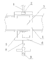
Fig. 1 is a front view of the present utility model;
Fig. 2 is a right view of the present utility model.
The specific embodiment
As shown in Figure 1 and Figure 2, this device is made up of forestope fixed mount 4, forestope locator and location-plate 6, and the forestope locator is by taking over a business 5 and take over a business to regulate screw mandrel 8 and form.Location-plate 6 both sides are provided with and are used to place and the forestope support tube 7 of mobile forestope 3, and location-plate 6 both sides are fixedly connected with back shaft, and forestope support 7 pipe boxes are combined on the back shaft.The nut 2 of forestope fixed mount 4 upper ends is connected with the anchor pole silk mouth 1 that anchor net spray supporting exposes.The forestope locator is threaded with the tapped through hole that is located at location-plate 6 centres, and a side of forestope locator is provided with cross-hole 9.
The operating principle of this device is as follows:
Install: during use, the nut 2 with forestope fixed mount 4 upper ends docks fixation with the anchor pole silk mouth 1 that anchor pole exposes earlier.Adjusting takes over a business to regulate screw mandrel 8, makes 5 to move down, and lifts forestope 3, by forestope support tube 7, forestope 3 is put into the space of forestope fixed mount 4, regulate and take over a business to regulate screw mandrel 8, take over a business on 5 to move, forestope 3 is securely fixed between the forestope fixed mount 4.
Move: when needing mobile forestope 3, adjusting takes over a business to regulate screw mandrel 8, take over a business 5 and move down, make forestope 3 loosening, forestope 3 is moved forward toward tunneling direction, and perpendicular to the cross section, tunnel, moving to needs the position, regulates and takes over a business to regulate screw mandrel 8, takes over a business on 5 and moves, after making forestope 3 fixations, jail, the back of the body are beaten in fact in the top of forestope 3.
Dismounting: when needing dismounting forestope 3, regulate and take over a business to regulate screw mandrel 8, take over a business 5 and move down, make forestope 3 loosening, extract forestope 3 out, and be placed on tunnel one side.When needing dismounting forestope fixed mount 4,, forestope fixed mount 4 can be separated with anchor pole 2 counter-rotatings of the nut on the forestope fixed mount 4.Forestope fixed mount 4 removes the back and is placed on tunnel one side and gets final product.
Explanation is at last, above embodiment is only unrestricted in order to the explanation the technical solution of the utility model, other modifications that those of ordinary skills make the technical solution of the utility model or be equal to replacement, only otherwise break away from the spirit and scope of technical solutions of the utility model, all should be encompassed in the middle of the claim scope of the present utility model.
Claims (2)
1. an anchor net spray supporting forestope fastening devices is characterized in that: be made up of forestope fixed mount, forestope locator and location-plate; The location-plate both sides are provided with and are used to place and the forestope support tube of mobile forestope, and the location-plate both sides are fixedly connected with back shaft, and the forestope support tube is linked on the back shaft; The nut of forestope fixed mount one end is connected with the anchor pole silk mouth that anchor net spray supporting exposes; The forestope locator is threaded with the tapped through hole that is located at the location-plate centre, and a side of forestope locator is provided with cross-hole.
2. anchor net spray supporting forestope fastening devices according to claim 1 is characterized in that: described forestope locator is formed by taking over a business and take over a business to regulate screw mandrel.
Priority Applications (1)
| Application Number | Priority Date | Filing Date | Title |
|---|---|---|---|
| CN2010205577559U CN201802423U (en) | 2010-10-12 | 2010-10-12 | Shotcrete rock-bolt wire-mesh support forestope fixing device |
Applications Claiming Priority (1)
| Application Number | Priority Date | Filing Date | Title |
|---|---|---|---|
| CN2010205577559U CN201802423U (en) | 2010-10-12 | 2010-10-12 | Shotcrete rock-bolt wire-mesh support forestope fixing device |
Publications (1)
| Publication Number | Publication Date |
|---|---|
| CN201802423U true CN201802423U (en) | 2011-04-20 |
Family
ID=43871928
Family Applications (1)
| Application Number | Title | Priority Date | Filing Date |
|---|---|---|---|
| CN2010205577559U Expired - Fee Related CN201802423U (en) | 2010-10-12 | 2010-10-12 | Shotcrete rock-bolt wire-mesh support forestope fixing device |
Country Status (1)
| Country | Link |
|---|---|
| CN (1) | CN201802423U (en) |
Cited By (1)
| Publication number | Priority date | Publication date | Assignee | Title |
|---|---|---|---|---|
| CN102900445A (en) * | 2012-11-12 | 2013-01-30 | 淮南矿业(集团)有限责任公司 | Temporary supporting device for anchor net roadway |
-
2010
- 2010-10-12 CN CN2010205577559U patent/CN201802423U/en not_active Expired - Fee Related
Cited By (2)
| Publication number | Priority date | Publication date | Assignee | Title |
|---|---|---|---|---|
| CN102900445A (en) * | 2012-11-12 | 2013-01-30 | 淮南矿业(集团)有限责任公司 | Temporary supporting device for anchor net roadway |
| CN102900445B (en) * | 2012-11-12 | 2015-10-21 | 淮南矿业(集团)有限责任公司 | Tunnel temporary support device |
Similar Documents
| Publication | Publication Date | Title |
|---|---|---|
| CN205532656U (en) | Deep well weak surrounding rock roadway support device | |
| CN102852550B (en) | Coal-pillar-free semi-normal-position goaf-side entry retaining method | |
| CN105201535A (en) | Resisting force dodging device for controlling floor heave, and construction method for device | |
| CN201794030U (en) | Continuous beam hanging basket forward movement traction device | |
| CN201802425U (en) | Device for fixing E type front canopy and F type front canopy of I-shaped steel support | |
| CN102287211A (en) | Gob roadway end part hydraulic support frame and gob roadway coal mining method thereof | |
| CN203128998U (en) | Temporary floating bridge for construction | |
| CN205277446U (en) | Colliery collecting space area roadway support device | |
| CN207538841U (en) | A kind of hydraulic tunnel inverted arch cambered surface slip form construction device | |
| CN205172592U (en) | A structure that is used for ore deposit to dig on method platform truck embedding slot saying fixed mounting | |
| CN201802421U (en) | Device for fixing beam support of U-shaped steel support for tunnel | |
| CN204419213U (en) | A set of high pre-stress girders anchorage cable linkage being convenient to stretch-draw and locking | |
| CN119009862A (en) | Prefabricated member for assembled power cable trench | |
| CN206647110U (en) | Tunnel pre-buried channel flow mounting structure | |
| CN206092025U (en) | Quick -witted bolting with wire mesh mechanism is constructed in colliery shield in pit | |
| CN202047853U (en) | Gob-side entry retaining end hydraulic support | |
| CN105937401B (en) | The method for protecting support in Liu Sheshuan lanes is once tunneled in a kind of U-shaped ventilation | |
| CN205277436U (en) | A device that is used for shield structure section of jurisdiction vertically taut | |
| CN201802422U (en) | Fixer of front canopy of I-shaped steel roadway support | |
| CN201802420U (en) | Device for fixing beam support of I-shaped steel support ceiling for tunnel | |
| CN109339480A (en) | Temporarily use movable plank house radix saposhnikoviae reinforcement means | |
| CN201802426U (en) | Roadway U-shaped steel support ceiling front canopy fixer | |
| CN218759943U (en) | Flexible protective net device for preventing rock falling from top of tunnel | |
| CN110374649B (en) | A kind of hanging rail type temporary support device and its walking method | |
| CN202900287U (en) | Secondary lining end mold structure of tunnel |
Legal Events
| Date | Code | Title | Description |
|---|---|---|---|
| C14 | Grant of patent or utility model | ||
| GR01 | Patent grant | ||
| CF01 | Termination of patent right due to non-payment of annual fee |
Granted publication date: 20110420 Termination date: 20141012 |
|
| EXPY | Termination of patent right or utility model |