CN201868687U - Electric connector - Google Patents
Electric connector Download PDFInfo
- Publication number
- CN201868687U CN201868687U CN2010205682659U CN201020568265U CN201868687U CN 201868687 U CN201868687 U CN 201868687U CN 2010205682659 U CN2010205682659 U CN 2010205682659U CN 201020568265 U CN201020568265 U CN 201020568265U CN 201868687 U CN201868687 U CN 201868687U
- Authority
- CN
- China
- Prior art keywords
- terminal
- lamellar body
- slot
- along
- electric connector
- Prior art date
- Legal status (The legal status is an assumption and is not a legal conclusion. Google has not performed a legal analysis and makes no representation as to the accuracy of the status listed.)
- Expired - Fee Related
Links
Images


Landscapes
- Coupling Device And Connection With Printed Circuit (AREA)
Abstract
本实用新型公开一种电连接器,其可沿着对接方向与对接插头对接,该电连接器包括绝缘本体、收容于绝缘本体内且沿着与对接方向垂直的横方向配置的一排第一端子模组、一排第二端子模组及接地片,所述第一端子模组包括第一片体及固持于第一片体上的若干第一端子,所述第二端子模组包括第二片体及固持于第二片体上的若干第二端子,其中,所述绝缘本体设有横向纵长开设的第一插槽、与第一插槽平行的第二插槽及位于第一、第二插槽之间的间隔部,间隔部上设有中间槽,一排第一端子模组的第一端子皆配置于第一插槽,一排第二端子模组的第二端子皆配置于第二插槽,接地片配置于中间槽且位于一排第一端子模组与一排第二端子模组之间。
The utility model discloses an electrical connector, which can be docked with a docking plug along a docking direction. A terminal module, a row of second terminal modules and grounding sheets, the first terminal module includes a first sheet and a number of first terminals fixed on the first sheet, the second terminal module includes a first Two pieces and a number of second terminals fixed on the second piece, wherein, the insulating body is provided with a first slot opened horizontally and vertically, a second slot parallel to the first slot, and a second slot located in the first slot. , The spacer between the second slots, the spacer is provided with a middle slot, the first terminals of a row of first terminal modules are all arranged in the first slot, and the second terminals of a row of second terminal modules are all It is arranged in the second slot, and the ground sheet is arranged in the middle slot and is located between a row of first terminal modules and a row of second terminal modules.
Description
【技术领域】【Technical field】
本实用新型关于一种电连接器,尤其是关于SFP(small form-factorpluggable)连接器的降低端子间串音干扰的接地片。The utility model relates to an electrical connector, in particular to a ground sheet for reducing crosstalk interference between terminals of an SFP (small form-factor pluggable) connector.
【背景技术】【Background technique】
CXP(C eXtended-capability Pluggable form-factor)连接器为SFP连接器中的一种连接器。CXP连接器的绝缘本体通常设有第一插槽、第二插槽及位于第一、第二插槽之间的间隔部。一排第一端子模组的第一上、下端子皆配置于第一插槽。一排第二端子模组的第二上、下端子皆配置于第二插槽。CXP连接器的遮蔽盖体一般由铸铁制造。CXP (C eXtended-capability Pluggable form-factor) connector is a kind of connector in SFP connector. The insulating body of the CXP connector is usually provided with a first slot, a second slot and a spacer between the first and second slots. The first upper and lower terminals of a row of first terminal modules are all configured in the first slot. The second upper and lower terminals of a row of second terminal modules are all configured in the second slot. The shielding cover of the CXP connector is generally made of cast iron.
2009年8月11日公告的公告号为7572156的美国专利及2010年3月9日公告的公告号7674133的美国专利揭示了一种SFP中的CXP连接器。所述CXP连接器包括绝缘本体、收容于绝缘本体内的若干晶片及套设于绝缘本体上的遮蔽盖体。各晶片上固持有上下对齐的一对第一端子及上下对齐的一对第二端子。US Patent No. 7572156 published on August 11, 2009 and US Patent No. 7674133 published on March 9, 2010 disclose a CXP connector in an SFP. The CXP connector includes an insulating body, a number of chips accommodated in the insulating body and a shielding cover set on the insulating body. A pair of first terminals aligned up and down and a pair of second terminals aligned up and down are fixed on each chip.
但是该设计的缺陷在于:一对第一端子与一对第二端子之间容易产生串音干扰。由于一对第一端子与一对第二端子设置于同一晶片上,晶片上难以于第一、第二端子之间设置接地片。故,如此设置的CXP连接器的第一、第二端子之间的串音干扰很难得到抑制。However, the disadvantage of this design is that crosstalk interference is easily generated between a pair of first terminals and a pair of second terminals. Since a pair of first terminals and a pair of second terminals are disposed on the same wafer, it is difficult to arrange a ground plate between the first and second terminals on the wafer. Therefore, it is difficult to suppress the crosstalk interference between the first and second terminals of the CXP connector thus arranged.
2004年3月30日公告的公告号为6712646的美国专利揭示了一种背板连接器。该背板连接器的插座包括绝缘本体、收容于绝缘本体内的上、下晶片、竖直配置的屏蔽片、水平配置的接地片及套设于绝缘本体上的遮蔽盖体。上晶片上固持有一对上端子。下晶片上固持有一对下端子。上晶片中间设有插设所述屏蔽片的插入槽。下晶片则配置于屏蔽片一侧。如此设置使得上、下晶片无法沿着对接方向对齐。屏蔽片上设有狭槽。接地片包括设有配合槽的水平部及竖直部。接地片通过其配合槽与屏蔽片的狭槽的配合固持于屏蔽片上。接地片的竖直部位于上、下晶片之间起到屏蔽作用。上、下端子之间的串音干扰得到有效控制。US Patent No. 6712646 published on March 30, 2004 discloses a backplane connector. The socket of the backplane connector includes an insulating body, upper and lower wafers accommodated in the insulating body, a vertically arranged shielding piece, a horizontally arranged grounding piece and a shielding cover set on the insulating body. A pair of upper terminals are fixed on the upper chip. A pair of lower terminals are fixed on the lower chip. An insertion slot for inserting the shielding sheet is provided in the middle of the upper wafer. The lower chip is arranged on one side of the shielding sheet. Such arrangement makes it impossible to align the upper and lower wafers along the butt joint direction. Slots are arranged on the shielding sheet. The ground sheet includes a horizontal part and a vertical part provided with matching grooves. The grounding piece is fixed on the shielding piece through the cooperation of its matching groove and the slot of the shielding piece. The vertical part of the ground sheet is located between the upper and lower chips to play a shielding role. The crosstalk interference between the upper and lower terminals is effectively controlled.
但是该设计为接地片于背板连接器上的应用,而未揭示接地片于SFP连接器上应用的可行性。该设计需通过设置竖直配置的屏蔽片才能固持接地片。同时设置垂直配置的屏蔽片与接地片令连接器结构复杂。另外,上、下晶片不对齐令组装过程复杂化。However, this design is the application of the ground sheet on the backplane connector, and does not disclose the feasibility of the application of the ground sheet on the SFP connector. This design needs to set up the shielding sheet arranged vertically to hold the grounding sheet. Simultaneously arranging the shielding sheet and the grounding sheet arranged vertically makes the structure of the connector complex. In addition, misalignment of the upper and lower wafers complicates the assembly process.
【实用新型内容】【Content of utility model】
本实用新型所要解决的技术问题在于将接地片应用于SFP连接器,从而得到一种可有效降低端子间串音干扰且制造容易的SFP连接器。The technical problem to be solved by the utility model is to apply the ground plate to the SFP connector, thereby obtaining an SFP connector that can effectively reduce crosstalk interference between terminals and is easy to manufacture.
为达到上述所要解决的技术问题,本实用新型提供一种电连接器,其可沿着对接方向与对接插头对接,该电连接器包括绝缘本体、收容于绝缘本体内且沿着与对接方向垂直的横方向配置的一排第一端子模组、一排第二端子模组及接地片,所述第一端子模组包括第一片体及固持于第一片体上的若干第一端子,所述第二端子模组包括第二片体及固持于第二片体上的若干第二端子,其中,所述绝缘本体设有横向纵长开设的第一插槽、与第一插槽平行的第二插槽及位于第一、第二插槽之间的间隔部,间隔部上设有中间槽,一排第一端子模组的第一端子皆配置于第一插槽,一排第二端子模组的第二端子皆配置于第二插槽,接地片配置于中间槽且位于一排第一端子模组与一排第二端子模组之间。In order to achieve the above-mentioned technical problems to be solved, the utility model provides an electrical connector, which can be docked with a docking plug along the docking direction. A row of first terminal modules, a row of second terminal modules, and a grounding sheet arranged in the transverse direction, the first terminal module includes a first sheet body and a plurality of first terminals held on the first sheet body, The second terminal module includes a second sheet body and a plurality of second terminals held on the second sheet body, wherein the insulating body is provided with a first slot opened horizontally and vertically, parallel to the first slot The second slot of the second slot and the spacer between the first and second slots, the spacer is provided with a middle groove, the first terminals of a row of first terminal modules are all arranged in the first slot, and the row of first terminal modules The second terminals of the two-terminal modules are all arranged in the second slots, and the ground sheet is arranged in the middle slot and is located between a row of first terminal modules and a row of second terminal modules.
与现有技术相比,本实用新型电连接器具有以下优点:本实用新型将接地片应用于SFP连接器。接地片的设置可有效降低第一端子与第二端子间的串音干扰。接地片直接插设于形成于第一片体与第二片体之间而令该电连接器结构简单且易于制造,同时可节约成本。Compared with the prior art, the electric connector of the utility model has the following advantages: the utility model applies the ground plate to the SFP connector. The arrangement of the ground sheet can effectively reduce the crosstalk interference between the first terminal and the second terminal. The ground sheet is directly inserted between the first sheet and the second sheet so that the structure of the electrical connector is simple and easy to manufacture, and at the same time the cost can be saved.
【附图说明】【Description of drawings】
图1是本实用新型电连接器与母电路板的立体组装图。Fig. 1 is a three-dimensional assembly diagram of the electric connector and the mother circuit board of the present invention.
图2是图1所示电连接器的部分分解图。FIG. 2 is a partially exploded view of the electrical connector shown in FIG. 1 .
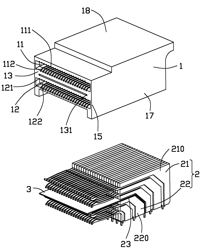
图3是图2所示的电连接器的插座的部分分解图。FIG. 3 is a partially exploded view of the receptacle of the electrical connector shown in FIG. 2 .
图4是图3的另一角度的部分分解图。FIG. 4 is a partially exploded view of FIG. 3 from another angle.
图5是图3所示的插座中的一个第一端子模组、一个第二端子模组与接地片的立体分解图。FIG. 5 is a three-dimensional exploded view of a first terminal module, a second terminal module and the ground plate in the socket shown in FIG. 3 .
图6是图3所示的第一、第二端子模组与接地片组装后的侧视图。Fig. 6 is a side view of the first and second terminal modules shown in Fig. 3 after being assembled with the grounding sheet.
【主要元件符号说明】[Description of main component symbols]
电连接器 100 插座 10
绝缘本体 1 第一插槽 11Insulation body 1 first slot 11
第一上端子槽 111 第一下端子槽 112First upper terminal slot 111 First lower terminal slot 112
第二插槽 12 第二上端子槽 121Second slot 12 Second upper terminal slot 121
第二下端子槽 122 间隔部 13Second lower terminal slot 122 Spacer part 13
中间槽 131 收容槽 14Middle tank 131 Storage tank 14
对接端 15 内壁 16Butt end 15 inner wall 16
侧壁 17 上壁 18side wall 17 upper wall 18
第一端子模组 21 第一片体 210The
第一上端子 21a 第一下端子 21bFirst
第一接触部 211 第一悬臂 212
第一固持部 213 第一弯折部 2131First holding
第一尾部 214 第二端子模组 22
第二片体 220 第二上端子 22a
第二下端子 22b 第二接触部 221Second
第二悬臂 222 第二固持部 223The
第二弯折部 2231 第二尾部 224The second bending
插入空间 23 接地片 3Insert space 23
水平部 31 弯折部 32
延伸部 33 接地脚 34
遮蔽盖体 4 突出部 41Shielding cover 4 protrusion 41
主体部 42 收容空间 43Main body 42 Containment space 43
开口 44 遮蔽片 5Opening 44 Masking sheet 5
母电路板 800
【具体实施方式】【Detailed ways】
请参阅图1及图2,本实用新型揭示一种电连接器100,其安装于母电路板800上且可沿着对接方向与对接连接器(未图示)对接。于本实施方式中该电连接器100即为CXP连接器。所述电连接器100包括:插座10、收容插座10的遮蔽盖体4及套设于遮蔽盖体4上的遮蔽片5。Please refer to FIG. 1 and FIG. 2 , the present invention discloses an
参阅图2至图4,插座10包括绝缘本体1、收容于绝缘本体1内且沿着与所述对接方向垂直的横方向配置的一排第一端子模组21、一排第二端子模组22及由金属片一体冲压成型的接地片3。Referring to Figures 2 to 4, the socket 10 includes an insulating body 1, a row of first
绝缘本体1前端设有对接端15、上壁18、内壁16、一对侧壁17及由上壁18、内壁16、一对侧壁17围设而成的收容槽14。绝缘本体1进一步设有横向纵长开设且向前延伸至对接端15的第一插槽11、与第一插槽11平行的第二插槽12及位于第一插槽11、第二插槽12之间的间隔部13。第一插槽11内设有一排第一上端子槽111及一排第一下端子槽112。第二插槽12内设有一排第二上端子槽121及一排第二下端子槽122。第一上、下端子槽111、112及第二上、下端子槽121、122向后贯穿内壁16并于内壁16上形成开孔状。间隔部13上设有中间槽131。所述中间槽131向前延伸至对接端15,向后贯穿内壁16以与收容槽14贯通。The front end of the insulating body 1 is provided with a butt end 15 , an upper wall 18 , an inner wall 16 , a pair of side walls 17 and a receiving groove 14 surrounded by the upper wall 18 , the inner wall 16 , and a pair of side walls 17 . The insulating body 1 is further provided with a first slot 11 that is opened vertically and horizontally and extends forward to the butt end 15, a second slot 12 parallel to the first slot 11, and a second slot 12 located between the first slot 11 and the second slot. 12 with a spacer 13 between them. A row of first upper terminal slots 111 and a row of first lower terminal slots 112 are disposed in the first slot 11 . A row of second upper terminal slots 121 and a row of second lower terminal slots 122 are disposed in the second slot 12 . The first upper and lower terminal grooves 111 , 112 and the second upper and lower terminal grooves 121 , 122 penetrate through the inner wall 16 backwards and form holes on the inner wall 16 . A middle groove 131 is formed on the spacer portion 13 . The middle groove 131 extends forward to the abutting end 15 , and passes through the inner wall 16 backward to communicate with the receiving groove 14 .
如图3至图6所示,所述第一端子模组21具有第一片体210及固持于第一片体210上的一对第一端子(未标号)。一对第一端子包括第一上端子21a及第一下端子21b。所述第二端子模组22具有第二片体220及固持于第二片体220上的一对第二端子(未标号)。一对第二端子包括第二上端子22a及第二下端子22b。As shown in FIGS. 3 to 6 , the
第一上、下端子21a、21b均具有固持于第一片体210上的第一固持部213、自第一固持部213延伸且离开第一片体210的第一悬臂212、设于第一悬臂212前端的第一接触部211、及自第一固持部213向下延伸的第一尾部214。第一固持部213上设有连续弯折两个相同角度的第一弯折部2131。第一上、下端子21a、21b的第一接触部211相向配置。第二上、下端子22a、22b均具有固持于第二片体220上的第二固持部223、自第二固持部223延伸且离开第二片体220的第二悬臂222、设于第二悬臂222前端的第二接触部221、及自第二固持部223向下延伸的第二尾部224。第二固持部223上设有连续弯折两个相同角度的第二弯折部2231。第二上、下端子22a、22b的第二接触部221相向配置。The first upper and
结合图5,第一上端子21a的第一悬臂212与第一下端子21b的第一悬臂212朝相反方向弯折一角度。结合图4,通过内壁16上的开孔设置可得知第一上端子21a的第一接触部211与第一下端子21b的第一接触部211沿着横方向偏移。同样的设置使得所述第二片体220上的第二上端子22a与第二下端子22b沿着横方向彼此偏移。第一片体210上的第一上端子21a的第一接触部211与第二片体220上的第二上端子22a的第二接触部221沿着上下方向对齐。第一片体210上的第一下端子21b的第一接触部211与第二片体220上的第二下端子22b的第二接触部221沿着上下方向对齐。从而可以与业界标准对接插头互配。Referring to FIG. 5 , the
接地片3包括水平部31、自水平部31弯折的弯折部32、自弯折部32向下延伸的延伸部33、及自延伸部33底部分别向下延伸的若干接地脚34。The
组装插座10时,将第一端子模组21、第二端子模组22及接地片3部分收容于收容槽14内。令第一端子模组21的第一上端子21a插设于第一上端子槽111,第一下端子21b插设于第一下端子槽112。令第二端子模组22的第二上端子22a插设于第二上端子槽121,第二下端子22b插设于第二下端子槽122。接地片3的水平部31固持于中间槽131内。接地片3的各接地脚34位于第一尾部214与对应的第二尾部224之间。When assembling the socket 10 , the
图3及图6揭示若干端子模组2与接地片3于绝缘本体1内的配置状况。所述一排第一端子模组21靠近所述一排第二端子模组22并与第二端子模组22相距一插入空间23用于收容接地片3。中间槽131亦构成插入空间23的一部分。各第一片体210与相应的一个第二片体220沿着对接方向对齐。FIG. 3 and FIG. 6 disclose the disposition of several terminal modules 2 and
所述若干第一片体210沿着横方向彼此堆叠且堆叠后具有所述横方向上的第一宽度。所述若干第二片体220沿着横方向彼此堆叠且堆叠后具有与第一宽度相等的第二宽度。接地片3沿着所述横方向具有第三宽度,所述第三宽度至少不小于第一宽度以实现对第一、第二端子的充分屏蔽。接地片3的水平部31的前端沿着对接方向越过第一、第二端子亦为实现对第一、第二端子的充分屏蔽。The plurality of
结合图4,相邻两个第一端子模组21上的第一尾部214沿着横方向彼此偏移。相邻两个第二端子模组22上的的第二尾部224亦沿着横方向彼此偏移。如此使得母电路板800上容易设置与第一、第二尾部214、224对应的孔。接地片3的接地脚34沿着横方向排列成一排。Referring to FIG. 4 , the
如图2所示,遮蔽盖体4包括主体部42及自主体部42向前突出的突出部41。主体部42内设有收容空间43及开口44。As shown in FIG. 2 , the shielding cover 4 includes a main body 42 and a protrusion 41 protruding forward from the main body 42 . A receiving space 43 and an opening 44 are defined in the main body portion 42 .
组装电连接器100时,将遮蔽片5套设于遮蔽盖体4上。将插座10焊接于母电路板800。将遮蔽盖体4压接于插座10上,令插座10自开口44收容于收容空间43内。When assembling the
接地片3应用于SFP连接器上以有效降低SFP连接器的第一端子与第二端子间的串音干扰。接地片3直接收容于第一端子模组21与第二端子模组22之间的插入空间23内而令该电连接器100结构简单。第一片体210与第二片体220沿着对接方向对齐,如此可简化组装过程。The
Claims (10)
Priority Applications (1)
| Application Number | Priority Date | Filing Date | Title |
|---|---|---|---|
| CN2010205682659U CN201868687U (en) | 2010-10-19 | 2010-10-19 | Electric connector |
Applications Claiming Priority (1)
| Application Number | Priority Date | Filing Date | Title |
|---|---|---|---|
| CN2010205682659U CN201868687U (en) | 2010-10-19 | 2010-10-19 | Electric connector |
Publications (1)
| Publication Number | Publication Date |
|---|---|
| CN201868687U true CN201868687U (en) | 2011-06-15 |
Family
ID=44139830
Family Applications (1)
| Application Number | Title | Priority Date | Filing Date |
|---|---|---|---|
| CN2010205682659U Expired - Fee Related CN201868687U (en) | 2010-10-19 | 2010-10-19 | Electric connector |
Country Status (1)
| Country | Link |
|---|---|
| CN (1) | CN201868687U (en) |
Cited By (29)
| Publication number | Priority date | Publication date | Assignee | Title |
|---|---|---|---|---|
| US9466930B2 (en) | 2013-07-19 | 2016-10-11 | Foxconn Interconnect Technology Limited | Flippable electrical connector |
| US9472911B2 (en) | 2013-07-19 | 2016-10-18 | Foxconn Interconnect Technology Limited | Flippable electrical connector with concentric inner and outer mating ports |
| US9472910B2 (en) | 2013-07-19 | 2016-10-18 | Foxconn Interconnect Technology Limited | Flippable electrical connector |
| US9484681B2 (en) | 2013-07-19 | 2016-11-01 | Foxconn Interconnect Technology Limited | Flippable electrical connector |
| US9490549B2 (en) | 2013-07-19 | 2016-11-08 | Foxconn Interconnect Technology Limited | Flippable electrical connector |
| US9490584B2 (en) | 2013-07-19 | 2016-11-08 | Foxconn Interconnect Technology Limited | Flippable electrical connector |
| US9490594B2 (en) | 2013-07-19 | 2016-11-08 | Foxconn Interconnect Technology Limited | Flippable electrical connector |
| US9490595B2 (en) | 2013-07-19 | 2016-11-08 | Foxconn Interconnect Technology Limited | Flippable electrical connector |
| US9490579B2 (en) | 2013-07-19 | 2016-11-08 | Foxconn Interconnect Technology Limited | Flippable Electrical Connector |
| US9496653B2 (en) | 2013-07-19 | 2016-11-15 | Foxconn Interconnect Technology Limited | Flippable electrical connector |
| US9496654B2 (en) | 2013-07-19 | 2016-11-15 | Foxconn Interconnect Technology Limited | Flippable electrical connector |
| US9496664B2 (en) | 2013-07-19 | 2016-11-15 | Foxconn Interconnect Technology Limited | Flippable electrical connector |
| US9502821B2 (en) | 2013-07-19 | 2016-11-22 | Foxconn Interconnect Technology Limited | Flippable electrical connector |
| US9520677B2 (en) | 2013-07-19 | 2016-12-13 | Foxconn Interconnect Technology Limited | Flippable electrical connector |
| US9660400B2 (en) | 2013-07-19 | 2017-05-23 | Foxconn Interconnect Technology Limited | Flippable electrical connector |
| US9755368B2 (en) | 2013-07-19 | 2017-09-05 | Foxconn Interconnect Technology Limited | Flippable electrical connector |
| US9762009B2 (en) | 2013-07-19 | 2017-09-12 | Foxconn Interconnect Technology Limited | Plug connector insertable in two orientations and having a metallic shield plate with arms with hook structures |
| CN107346843A (en) * | 2016-05-07 | 2017-11-14 | 富士康(昆山)电脑接插件有限公司 | Socket connector |
| US9843148B2 (en) | 2013-07-19 | 2017-12-12 | Foxconn Interconnect Technology Limited | Flippable electrical connector |
| US9905944B2 (en) | 2013-07-19 | 2018-02-27 | Foxconn Interconnect Technology Limited | Flippable electrical connector |
| US9912111B2 (en) | 2013-07-19 | 2018-03-06 | Foxconn Interconnect Technology Limited | Flippable electrical connector |
| US9997853B2 (en) | 2013-07-19 | 2018-06-12 | Foxconn Interconnect Technology Limited | Flippable electrical connector |
| US10170870B2 (en) | 2013-07-19 | 2019-01-01 | Foxconn Interconnect Technology Limited | Flippable electrical connector |
| CN109728453A (en) * | 2017-10-26 | 2019-05-07 | 富士康(昆山)电脑接插件有限公司 | Electric connector |
| CN110021839A (en) * | 2018-01-06 | 2019-07-16 | 富士康(昆山)电脑接插件有限公司 | Jack connector assembly |
| CN110137722A (en) * | 2018-02-09 | 2019-08-16 | 富士康(昆山)电脑接插件有限公司 | Socket connector |
| US10693261B2 (en) | 2013-07-19 | 2020-06-23 | Foxconn Interconnect Technology Limited | Flippable electrical connector |
| US10720734B2 (en) | 2013-07-19 | 2020-07-21 | Foxconn Interconnect Technology Limited | Flippable electrical connector |
| US10826255B2 (en) | 2013-07-19 | 2020-11-03 | Foxconn Interconnect Technology Limited | Flippable electrical connector |
-
2010
- 2010-10-19 CN CN2010205682659U patent/CN201868687U/en not_active Expired - Fee Related
Cited By (40)
| Publication number | Priority date | Publication date | Assignee | Title |
|---|---|---|---|---|
| US9755368B2 (en) | 2013-07-19 | 2017-09-05 | Foxconn Interconnect Technology Limited | Flippable electrical connector |
| US9520677B2 (en) | 2013-07-19 | 2016-12-13 | Foxconn Interconnect Technology Limited | Flippable electrical connector |
| US9472910B2 (en) | 2013-07-19 | 2016-10-18 | Foxconn Interconnect Technology Limited | Flippable electrical connector |
| US9484681B2 (en) | 2013-07-19 | 2016-11-01 | Foxconn Interconnect Technology Limited | Flippable electrical connector |
| US9490549B2 (en) | 2013-07-19 | 2016-11-08 | Foxconn Interconnect Technology Limited | Flippable electrical connector |
| US9490584B2 (en) | 2013-07-19 | 2016-11-08 | Foxconn Interconnect Technology Limited | Flippable electrical connector |
| US9490594B2 (en) | 2013-07-19 | 2016-11-08 | Foxconn Interconnect Technology Limited | Flippable electrical connector |
| US9490595B2 (en) | 2013-07-19 | 2016-11-08 | Foxconn Interconnect Technology Limited | Flippable electrical connector |
| US9490579B2 (en) | 2013-07-19 | 2016-11-08 | Foxconn Interconnect Technology Limited | Flippable Electrical Connector |
| US9496653B2 (en) | 2013-07-19 | 2016-11-15 | Foxconn Interconnect Technology Limited | Flippable electrical connector |
| US9496654B2 (en) | 2013-07-19 | 2016-11-15 | Foxconn Interconnect Technology Limited | Flippable electrical connector |
| US9496664B2 (en) | 2013-07-19 | 2016-11-15 | Foxconn Interconnect Technology Limited | Flippable electrical connector |
| US9502841B2 (en) | 2013-07-19 | 2016-11-22 | Foxconn Interconnect Technology Limited | Flippable electrical connector |
| US9502821B2 (en) | 2013-07-19 | 2016-11-22 | Foxconn Interconnect Technology Limited | Flippable electrical connector |
| US9748702B2 (en) | 2013-07-19 | 2017-08-29 | Foxconn Interconnect Technology Limited | Flippable electrical connector |
| US9583900B2 (en) | 2013-07-19 | 2017-02-28 | Foxconn Interconnect Technology Limited | Flippable electrical connector |
| US9608391B2 (en) | 2013-07-19 | 2017-03-28 | Foxconn Interconnect Technology Limited | Flippable electrical connector |
| US9660400B2 (en) | 2013-07-19 | 2017-05-23 | Foxconn Interconnect Technology Limited | Flippable electrical connector |
| US9472911B2 (en) | 2013-07-19 | 2016-10-18 | Foxconn Interconnect Technology Limited | Flippable electrical connector with concentric inner and outer mating ports |
| US9698536B2 (en) | 2013-07-19 | 2017-07-04 | Foxconn Interconnect Technology Limited | Flippable electrical connector |
| US9843148B2 (en) | 2013-07-19 | 2017-12-12 | Foxconn Interconnect Technology Limited | Flippable electrical connector |
| US9755380B2 (en) | 2013-07-19 | 2017-09-05 | Foxconn Interconnect Technology Limited | Flippable electrical connector |
| US9762009B2 (en) | 2013-07-19 | 2017-09-12 | Foxconn Interconnect Technology Limited | Plug connector insertable in two orientations and having a metallic shield plate with arms with hook structures |
| US9761995B2 (en) | 2013-07-19 | 2017-09-12 | Foxconn Interconnect Technology Limited | Flippable Electrical Connector |
| US10826255B2 (en) | 2013-07-19 | 2020-11-03 | Foxconn Interconnect Technology Limited | Flippable electrical connector |
| US9466930B2 (en) | 2013-07-19 | 2016-10-11 | Foxconn Interconnect Technology Limited | Flippable electrical connector |
| US9905944B2 (en) | 2013-07-19 | 2018-02-27 | Foxconn Interconnect Technology Limited | Flippable electrical connector |
| US9912111B2 (en) | 2013-07-19 | 2018-03-06 | Foxconn Interconnect Technology Limited | Flippable electrical connector |
| US9997853B2 (en) | 2013-07-19 | 2018-06-12 | Foxconn Interconnect Technology Limited | Flippable electrical connector |
| US10158197B2 (en) | 2013-07-19 | 2018-12-18 | Foxconn Interconnect Technology Limited | Flippable electrical connector |
| US10170870B2 (en) | 2013-07-19 | 2019-01-01 | Foxconn Interconnect Technology Limited | Flippable electrical connector |
| US10720734B2 (en) | 2013-07-19 | 2020-07-21 | Foxconn Interconnect Technology Limited | Flippable electrical connector |
| US10312646B2 (en) | 2013-07-19 | 2019-06-04 | Foxconn Interconnect Technology Limited | Flippable electrical connector |
| US10693261B2 (en) | 2013-07-19 | 2020-06-23 | Foxconn Interconnect Technology Limited | Flippable electrical connector |
| CN107346843B (en) * | 2016-05-07 | 2020-06-02 | 富士康(昆山)电脑接插件有限公司 | Socket connector |
| CN107346843A (en) * | 2016-05-07 | 2017-11-14 | 富士康(昆山)电脑接插件有限公司 | Socket connector |
| CN109728453A (en) * | 2017-10-26 | 2019-05-07 | 富士康(昆山)电脑接插件有限公司 | Electric connector |
| CN109728453B (en) * | 2017-10-26 | 2021-10-26 | 富士康(昆山)电脑接插件有限公司 | Electrical connector |
| CN110021839A (en) * | 2018-01-06 | 2019-07-16 | 富士康(昆山)电脑接插件有限公司 | Jack connector assembly |
| CN110137722A (en) * | 2018-02-09 | 2019-08-16 | 富士康(昆山)电脑接插件有限公司 | Socket connector |
Similar Documents
| Publication | Publication Date | Title |
|---|---|---|
| CN201868687U (en) | Electric connector | |
| CN201266735Y (en) | Electric connector | |
| CN204243365U (en) | electrical connector | |
| US8262414B1 (en) | Connector | |
| US8979551B2 (en) | Low-profile mezzanine connector | |
| CN102377053B (en) | Electric connector | |
| JP5825477B2 (en) | Connector | |
| CN101471515A (en) | Electric connector | |
| US7736176B2 (en) | Modular jack assembly having improved connecting terminal | |
| US20150024614A1 (en) | Electrical connector having a shielding member disposed between two magnetic modules | |
| TW201324969A (en) | Staggered mounting electrical connector | |
| KR20140119794A (en) | Connector receptacle having split contacts | |
| KR20120022624A (en) | Electrical connector and circuit board assembly | |
| US8641455B2 (en) | Universal serial bus connector perpendicularly mounted on a printed circuit board | |
| CN116231359A (en) | electrical connector | |
| CN202585983U (en) | Electric connector combination | |
| CN202189917U (en) | Electric connector | |
| CN204243314U (en) | Socket connector | |
| CN201667443U (en) | electrical connector | |
| CN202917721U (en) | Socket connector and plug connector | |
| CN102412455A (en) | Electrical connector and method for making the same | |
| CN201029176Y (en) | electrical connector | |
| CN205752634U (en) | Electric connector for socket | |
| CN102377043B (en) | Electrical connector and electrical connection method thereof | |
| JP2011082048A (en) | Male connector, connector, and backplane |
Legal Events
| Date | Code | Title | Description |
|---|---|---|---|
| C14 | Grant of patent or utility model | ||
| GR01 | Patent grant | ||
| C17 | Cessation of patent right | ||
| CF01 | Termination of patent right due to non-payment of annual fee |
Granted publication date: 20110615 Termination date: 20131019 |