CN201883473U - Novel water supply equipment without negative pressure - Google Patents

Novel water supply equipment without negative pressure Download PDF

Info

Publication number
CN201883473U
CN201883473U CN2010205797309U CN201020579730U CN201883473U CN 201883473 U CN201883473 U CN 201883473U CN 2010205797309 U CN2010205797309 U CN 2010205797309U CN 201020579730 U CN201020579730 U CN 201020579730U CN 201883473 U CN201883473 U CN 201883473U
Authority
CN
China
Prior art keywords
water
water supply
tank
negative pressure
supply equipment
Prior art date
Legal status (The legal status is an assumption and is not a legal conclusion. Google has not performed a legal analysis and makes no representation as to the accuracy of the status listed.)
Expired - Fee Related
Application number
CN2010205797309U
Other languages
Chinese (zh)
Inventor
尹承民
尹延京
王培宽
徐士刚
Current Assignee (The listed assignees may be inaccurate. Google has not performed a legal analysis and makes no representation or warranty as to the accuracy of the list.)
Individual
Original Assignee
Individual
Priority date (The priority date is an assumption and is not a legal conclusion. Google has not performed a legal analysis and makes no representation as to the accuracy of the date listed.)
Filing date
Publication date
Application filed by Individual filed Critical Individual
Priority to CN2010205797309U priority Critical patent/CN201883473U/en
Application granted granted Critical
Publication of CN201883473U publication Critical patent/CN201883473U/en
Anticipated expiration legal-status Critical
Expired - Fee Related legal-status Critical Current

Links

Images

Classifications

    • Y—GENERAL TAGGING OF NEW TECHNOLOGICAL DEVELOPMENTS; GENERAL TAGGING OF CROSS-SECTIONAL TECHNOLOGIES SPANNING OVER SEVERAL SECTIONS OF THE IPC; TECHNICAL SUBJECTS COVERED BY FORMER USPC CROSS-REFERENCE ART COLLECTIONS [XRACs] AND DIGESTS
    • Y02—TECHNOLOGIES OR APPLICATIONS FOR MITIGATION OR ADAPTATION AGAINST CLIMATE CHANGE
    • Y02A—TECHNOLOGIES FOR ADAPTATION TO CLIMATE CHANGE
    • Y02A20/00—Water conservation; Efficient water supply; Efficient water use

Landscapes

  • Devices For Dispensing Beverages (AREA)

Abstract

本实用新型公开了一种新型无负压供水设备,属于供水设备,特别是对自来水管网没有压力影响的无负压供水设备。该新型无负压供水设备,包括由封头和罐体组成的储水罐安装在底座支架上、罐体上有进水口和出水口,其特征是:进水口安装在罐体顶部,进水口下面连接着底端为45°角的进水内管,罐体顶部的测压口上装有压力传感器,罐体顶部的真空抑制器接口上装有真空抑制器,出水口安装在罐体底部。本实用新型的有益效果是进水口与出水口可以顺畅进水和供水,即使出水量较大也不会形成对口抽,不会对自来水管网造成影响,经过罐体的水可以浸出矿化物填料中的微量元素,使供水矿化提高所供水的品位有益于人们身体健康。

Figure 201020579730

The utility model discloses a new type of non-negative pressure water supply equipment, which belongs to the water supply equipment, in particular to the non-negative pressure water supply equipment which has no pressure influence on the tap water pipe network. This new type of non-negative pressure water supply equipment includes a water storage tank composed of a head and a tank body installed on the base bracket, and the tank body has a water inlet and a water outlet. Its characteristics are: the water inlet is installed on the top of the tank body, and the water inlet The bottom is connected with the water inlet inner pipe at an angle of 45° below, a pressure sensor is installed on the pressure measuring port on the top of the tank, a vacuum suppressor is installed on the vacuum suppressor interface on the top of the tank, and the water outlet is installed at the bottom of the tank. The beneficial effect of the utility model is that the water inlet and the water outlet can smoothly enter and supply water, even if the water output is large, it will not form a counterpart pump, and will not affect the tap water pipe network, and the water passing through the tank can leach mineral fillers The trace elements in the water supply can mineralize the water supply and improve the grade of the water supply, which is beneficial to people's health.

Figure 201020579730

Description

Novel non-negative pressure water supply equipment
Technical field
The utility model belongs to supply equipment, particularly the tap water pipe network is not had the non-negative pressure water-supply installation of pressure influence.
Background technology
Common supply equipment is owing to adopt water pump to carry out the secondary pressurization, little or when cutting off the water when tap water pipe network pressure, water pump can produce negative pressure to the tap water pipe network, influencing pipe network normally moves, in order to solve of the influence of secondary water-supply equipment to pipe network, usually use methods such as reservoir, high level cistern, these methods extensively contact water with air in reservoir, easily water is polluted.
The utility model content
In order to overcome the deficiency that existing supply equipment can produce negative pressure to the tap water pipe network, the utility model provides a kind of novel non-negative pressure water supply equipment, and this novel non-negative pressure water supply equipment not only can not produce negative pressure to pipe network, and can avoid contacting of water and air.
The technical scheme that its technical problem that solves the utility model adopts is: a kind of novel non-negative pressure water supply equipment, comprise by water storage tank body, water supply pump and electrical control cabinet, it is characterized in that: water inlet is installed in water storage tank body top, connecting the bottom below the water inlet is the interior pipe of water inlet of 45, on the pressure tap at tank body top pressure sensor is housed, on the vacuum suppresser interface at tank body top vacuum suppresser is housed, delivery port is installed in tank base, is connected delivery port water supply pump and water supply network and joins.
Periphery is housed for netted floral tube below the described vacuum suppresser interface, the mineralizer filler is housed in the floral tube, described mineralizer filler is wooden fish stone or medical stone.
The pressure sensor on the data acquisition end of described electrical control cabinet and the water tank pressure tap and the pressure sensor of exit of pump are connected, and control end is connected with water pump through frequency converter.
The beneficial effects of the utility model are owing to installed below water inlet in the water inlet that the bottom is a 45 and manage, delivery port is located at below the tank body, the water inlet water of coming in can enter water supply line from delivery port through water pump rapidly like this, water inlet and delivery port can smooth and easy water inlet water supply, even water yield more can not form counterpart more yet and take out, can not impact the tap water pipe network, moreover, because the inner floral tube that mineral filler is housed has been installed below the vacuum suppresser interface, the water of process tank body can leach the trace element in the mineralizer filler, and it is healthy that the grade that the raising of water supply mineralising is supplied water is of value to people.
Description of drawings
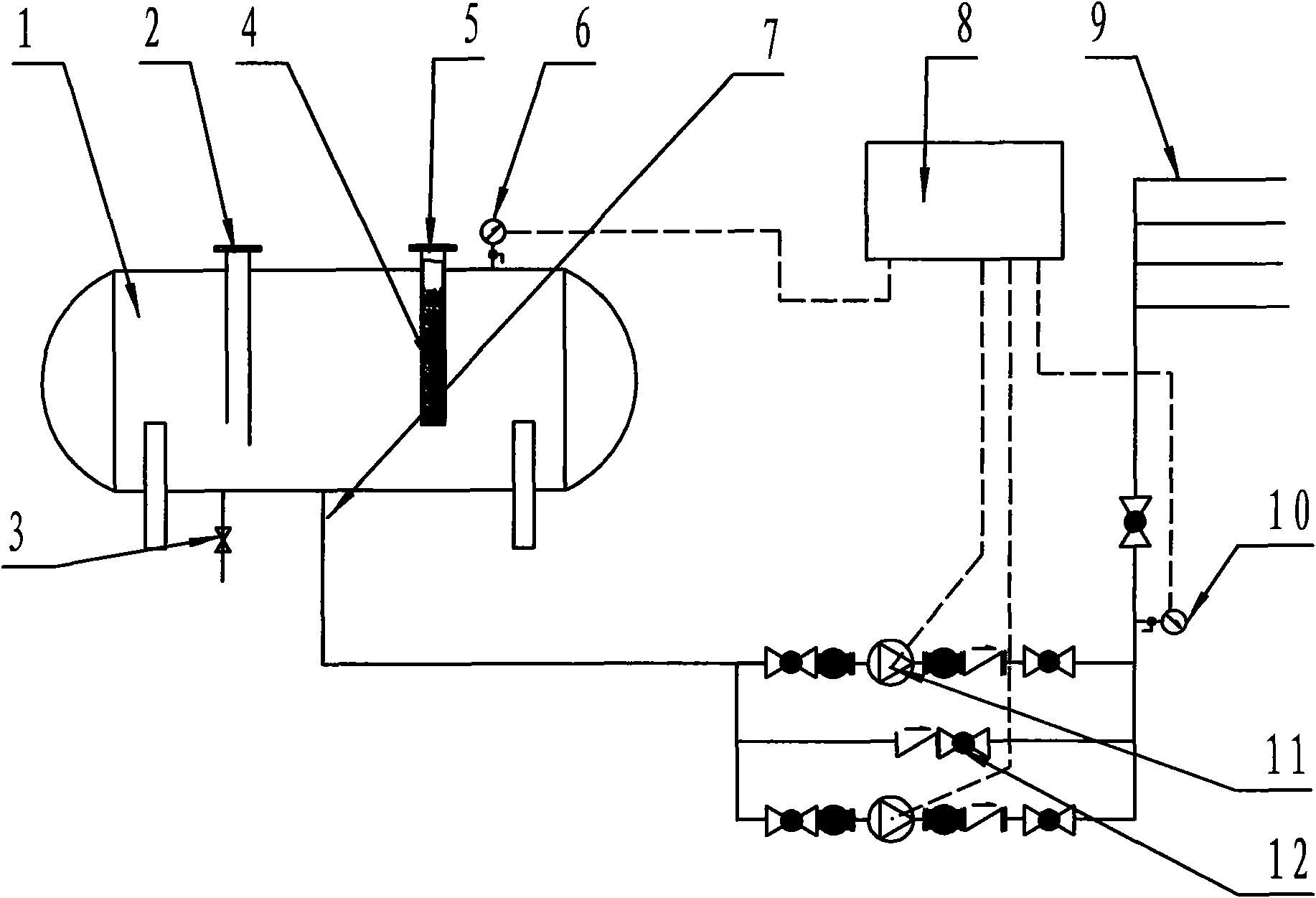
Fig. 1 is a structural representation of the present utility model,
Among the figure, 1. water storage tank body, 2. water inlet, 3. sewage draining exit, 4. mineralizer filler, 5. vacuum suppresser interface, 6. pressure sensor, 7. delivery port, 8. electric controller, 9. water supply network, 10. delivery port pressure sensor, 11. water supply pumps, 12 one way valves.
The specific embodiment
The specific embodiment of the present utility model is, as shown in the figure:
Embodiment 1, a kind of novel non-negative pressure water supply equipment, comprise by water storage tank body 1, water supply pump 11 and electrical control cabinet 8, sewage draining exit 3, it is characterized in that: water inlet 2 is installed in the tank body top, connecting the bottom below the water inlet is the interior pipe of water inlet of 45, and pressure sensor 6 is housed on the pressure tap at tank body top, on the vacuum suppresser interface 5 at tank body top vacuum suppresser is housed, delivery port is installed in tank base, is connected the delivery port water supply pump and water supply network 9 joins.The pressure sensor on the data acquisition end of electrical control cabinet and the water tank pressure tap and the delivery port pressure sensor 10 of exit of pump are connected, and control end is connected with water supply pump through frequency converter.
Embodiment 2, a kind of novel non-negative pressure water supply equipment, comprise by water storage tank body 1, water supply pump 11 and electrical control cabinet 8, sewage draining exit 3, it is characterized in that: water inlet 2 is installed in the tank body top, connecting the bottom below the water inlet is the interior pipe of water inlet of 45, and pressure sensor 6 is housed on the pressure tap at tank body top, on the vacuum suppresser interface 5 at tank body top vacuum suppresser is housed, delivery port is installed in tank base, is connected the delivery port water supply pump and water supply network 9 joins.The pressure sensor on the data acquisition end of electrical control cabinet and the water tank pressure tap and the delivery port pressure sensor 10 of exit of pump are connected, and control end is connected with water supply pump through frequency converter.Periphery is housed for netted floral tube below the described vacuum suppresser interface, mineralizer fillers 4 such as wooden fish stone, medical stone are housed in the floral tube.

Claims (3)

1.一种新型无负压供水设备,包括由储水罐体、供水水泵及电气控制柜,其特征是:进水口安装在储水罐体顶部,进水口下面连接着底端为45°角的进水内管,罐体顶部的测压口上装有压力传感器,罐体顶部的真空抑制器接口上装有真空抑制器,出水口安装在罐体底部,连接在出水口供水水泵与供水管网相接。1. A new type of non-negative pressure water supply equipment, including a water storage tank, a water supply pump and an electrical control cabinet. It is characterized in that: the water inlet is installed on the top of the water storage tank, and the bottom of the water inlet is connected at an angle of 45° The inner pipe of the water inlet, the pressure measuring port on the top of the tank is equipped with a pressure sensor, the vacuum suppressor interface on the top of the tank is equipped with a vacuum suppressor, the water outlet is installed at the bottom of the tank, and connected to the water supply pump at the water outlet and the water supply pipe network connect. 2.根据权利要求1所述的新型无负压供水设备,其特征是:所述的真空抑制器接口下面装有周边为网状的花管,花管内装有矿化物填料,所述的矿化物填料为木鱼石或麦饭石。2. The new type non-negative pressure water supply equipment according to claim 1, characterized in that: a flower tube with a meshed periphery is installed under the interface of the vacuum suppressor, and mineral fillers are installed in the flower tube, and the mineral filler is arranged in the flower tube. The compound filler is wood fish stone or medical stone. 3.根据权利要求1所述的新型无负压供水设备,其特征是:所述的电气控制柜的数据采集端与储水罐测压口上的压力传感器及水泵出口的压力传感器相连接,控制端经变频器与水泵相连接。 3. The novel non-negative pressure water supply equipment according to claim 1, characterized in that: the data acquisition end of the electrical control cabinet is connected with the pressure sensor on the pressure measuring port of the water storage tank and the pressure sensor at the outlet of the water pump to control The terminal is connected to the water pump through the frequency converter. the
CN2010205797309U 2010-10-28 2010-10-28 Novel water supply equipment without negative pressure Expired - Fee Related CN201883473U (en)

Priority Applications (1)

Application Number Priority Date Filing Date Title
CN2010205797309U CN201883473U (en) 2010-10-28 2010-10-28 Novel water supply equipment without negative pressure

Applications Claiming Priority (1)

Application Number Priority Date Filing Date Title
CN2010205797309U CN201883473U (en) 2010-10-28 2010-10-28 Novel water supply equipment without negative pressure

Publications (1)

Publication Number Publication Date
CN201883473U true CN201883473U (en) 2011-06-29

Family

ID=44181011

Family Applications (1)

Application Number Title Priority Date Filing Date
CN2010205797309U Expired - Fee Related CN201883473U (en) 2010-10-28 2010-10-28 Novel water supply equipment without negative pressure

Country Status (1)

Country Link
CN (1) CN201883473U (en)

Cited By (1)

* Cited by examiner, † Cited by third party
Publication number Priority date Publication date Assignee Title
CN103485389A (en) * 2012-06-11 2014-01-01 四川制药制剂有限公司 Steady-pressure water supply system for pharmaceutical workshop

Cited By (1)

* Cited by examiner, † Cited by third party
Publication number Priority date Publication date Assignee Title
CN103485389A (en) * 2012-06-11 2014-01-01 四川制药制剂有限公司 Steady-pressure water supply system for pharmaceutical workshop

Similar Documents

Publication Publication Date Title
CN204560482U (en) Automatic watering device for flowers
CN203691930U (en) Automatic biogas slurry irrigation device
CN104746576A (en) Water tank adjustment and storage variable voltage transformation pipe network pressure-superposed water supply device
CN205242517U (en) A intelligent time control transition system for water supply equipment
CN201050086Y (en) Negative pressure free water tank frequency conversion water supplying system
CN202175985U (en) Water supply device
CN205408806U (en) Automatic flower watering machine
CN203944170U (en) Valveless filtering pool
CN203866900U (en) Silent water supplying tank device
CN205804466U (en) Water pump ftercompction formula non-negative pressure water service system
CN207362937U (en) Pump is super-silent in tank laminates water supply integrated apparatus
CN203782805U (en) Box type non-negative pressure water supply equipment
CN204112410U (en) Normal effect automatic sterilization non-negative pressure water-supply installation
CN202064400U (en) Household surface water supply device
CN203027813U (en) Flowerpot with goldfish bowl
CN203741944U (en) Pressurization and storage adjustment intelligent water supply device directly connected with pipe network in series
CN204781124U (en) Case pump integration water supply installation
CN203290742U (en) Water dispenser with automatic water-adding function
CN202514425U (en) Fish tank
CN205409057U (en) Hamster drinking bowl of controllable water
CN203112479U (en) Balanced filling system
CN202658950U (en) Ventilation pressurizing water tower
CN204385832U (en) A kind of toilet with water economizer
CN204146129U (en) With the watering can of automatic watering structure
CN203878661U (en) Direct connection isolation device

Legal Events

Date Code Title Description
C14 Grant of patent or utility model
GR01 Patent grant
CF01 Termination of patent right due to non-payment of annual fee

Granted publication date: 20110629

Termination date: 20141028

EXPY Termination of patent right or utility model