CN201916411U - Automobile shock absorber - Google Patents
Automobile shock absorber Download PDFInfo
- Publication number
- CN201916411U CN201916411U CN2010206676941U CN201020667694U CN201916411U CN 201916411 U CN201916411 U CN 201916411U CN 2010206676941 U CN2010206676941 U CN 2010206676941U CN 201020667694 U CN201020667694 U CN 201020667694U CN 201916411 U CN201916411 U CN 201916411U
- Authority
- CN
- China
- Prior art keywords
- housing
- casing
- hydraulic chamber
- shock absorber
- automobile
- Prior art date
- Legal status (The legal status is an assumption and is not a legal conclusion. Google has not performed a legal analysis and makes no representation as to the accuracy of the status listed.)
- Expired - Fee Related
Links
Images


Landscapes
- Vehicle Body Suspensions (AREA)
Abstract
本实用新型提供了一种汽车减震器,属于汽车部件技术领域。它解决了现有汽车减震器存在减震效果差、无法提高汽车底盘高度等技术问题。本汽车减震器,包括内部具有液压腔一的壳体一、活塞杆、油封、顶阀和底阀,在壳体一外侧套设有壳体二,且所述的壳体二能沿着上述的壳体一上下滑动,所述的壳体二内部具有液压腔二,上述的活塞杆穿过壳体二的液压腔二,所述的壳体二的外侧还套设有能沿着壳体二上下滑动的壳体三,所述的壳体三内部具有液压腔三,上述的活塞杆穿出壳体二进入到壳体三的液压腔三内。本实用新型具有设计合理、安装方便、成本较低、能有效的提高或降低汽车底盘等优点。
The utility model provides an automobile shock absorber, which belongs to the technical field of automobile parts. The invention solves the technical problems of poor damping effect and inability to increase the height of the chassis of the automobile existing in the existing automobile shock absorber. The automobile shock absorber includes a housing 1 with a hydraulic chamber 1 inside, a piston rod, an oil seal, a top valve and a bottom valve, and a housing 2 is sleeved on the outside of the housing 1, and the housing 2 can move along the The above-mentioned casing 1 slides up and down, the inside of the casing 2 has a hydraulic chamber 2, the above-mentioned piston rod passes through the hydraulic chamber 2 of the casing 2, and the outer side of the casing 2 is also sleeved with a The body 2 slides up and down the casing 3, the casing 3 has a hydraulic chamber 3 inside, and the above-mentioned piston rod passes through the casing 2 and enters the hydraulic chamber 3 of the casing 3. The utility model has the advantages of reasonable design, convenient installation, low cost, effective improvement or reduction of the automobile chassis and the like.
Description
技术领域technical field
本实用新型属于汽车部件技术领域,涉及一种汽车减震器,特别是一种能提高或降低汽车底盘高度的汽车减震器。The utility model belongs to the technical field of automobile parts, and relates to an automobile shock absorber, in particular to an automobile shock absorber capable of raising or lowering the height of an automobile chassis.
背景技术Background technique
悬架是汽车的车架与车桥或车轮之间的一切传力连接装置的总称,其作用是传递作用在车轮和车架之间的力和力扭,并且缓冲由不平路面传给车架或车身的冲击力,并衰减由此引起的震动,以保证汽车能平顺地行驶。典型汽车悬架包括弹性元件、减振器和传力装置等三部分,这三部分分别起缓冲,减振和力的传递作用。弹性元件用力传递垂向力,并缓和由路面不平度引起的冲击和振动。从轿车上来讲,弹性元件多指螺旋弹簧,它只承受垂直载荷,缓和及抑制不平路面对车体的冲击,具有占用空间小,质量小,无需润滑的优点。减振器指液力减振器,是为了加速衰减车身的振动。传力装置用来传递纵向力,侧向力及力矩,并保证车轮相对于车架或车身有确定的相对运动规律。Suspension is the general term for all force-transmitting connection devices between the frame of a car and the axle or wheels. Or the impact force of the car body, and attenuate the vibration caused by it, so as to ensure that the car can run smoothly. A typical automobile suspension includes three parts: elastic elements, shock absorbers and force transmission devices. These three parts play the roles of buffering, vibration reduction and force transmission respectively. The elastic elements actively transmit vertical forces and dampen shocks and vibrations caused by road irregularities. From the point of view of the car, the elastic element refers to the coil spring, which only bears the vertical load, eases and suppresses the impact of the uneven road on the car body, and has the advantages of small space occupation, low mass and no need for lubrication. The shock absorber refers to the hydraulic shock absorber, which is to accelerate the attenuation of the vibration of the vehicle body. The force transmission device is used to transmit longitudinal force, lateral force and moment, and ensure that the wheel has a certain relative motion law relative to the frame or body.
目前,现有的减振器如图4所示,包括内部具有液压腔一11的壳体一1、活塞杆2、油封3、顶阀4和底阀5,所述的顶阀5设置在液压腔一11的顶部,所述的底阀5设置在液压腔一11的底部,所述的油封3设置在液压腔一11内,所述的活塞杆2一端与上述的油封3相固连,另一端穿出上述的顶阀5。由这样的减震器组成的悬架,一旦装车后,车辆底盘距地面的高度也基本固定了。这样的汽车悬架无法满足车主在市区驾车需降低车辆底盘或野外驾车需升高的底盘的需要。At present, as shown in Figure 4, the existing shock absorber includes a housing-1 with a hydraulic chamber-11 inside, a
发明内容Contents of the invention
本实用新型的目的是针对现有的技术存在上述问题,提出了一种能根据实际需要提高或降低汽车底盘的汽车减震器。The purpose of this utility model is to propose a kind of automobile shock absorber that can raise or lower the chassis of the automobile according to the actual needs in order to solve the problems mentioned above in the prior art.
本实用新型的目的可通过下列技术方案来实现:一种汽车减震器,包括内部具有液压腔一的壳体一、活塞杆、油封、顶阀和底阀,所述的顶阀设置在液压腔一的顶部,所述的底阀设置在液压腔一的底部,所述的油封设置在液压腔一内,所述的活塞杆一端与上述的油封相固连,另一端穿出上述的顶阀,其特征在于,所述的壳体一外侧套设有壳体二,且所述的壳体二能沿着上述的壳体一上下滑动,所述的壳体二内部具有液压腔二,上述的活塞杆穿过壳体二的液压腔二,所述的壳体二的外侧还套设有能沿着壳体二上下滑动的壳体三,所述的壳体三内部具有液压腔三,上述的活塞杆穿出壳体二进入到壳体三的液压腔三内。The purpose of this utility model can be achieved through the following technical proposals: a kind of automobile shock absorber, including the housing 1 with hydraulic cavity 1 inside, piston rod, oil seal, top valve and bottom valve, described top valve is arranged on hydraulic pressure the top of chamber 1, the bottom valve is set at the bottom of hydraulic chamber 1, the oil seal is set in hydraulic chamber 1, one end of the piston rod is fixedly connected with the above oil seal, and the other end passes through the above-mentioned top The valve is characterized in that the outer side of the first casing is covered with the second casing, and the second casing can slide up and down along the first casing, and the second casing has a hydraulic chamber inside, The above-mentioned piston rod passes through the
本汽车减震器是用来作为汽车悬架的重要部件,本汽车减震器的壳体一的上端是与弹性元件相连的,壳体三的下端是与传力装置相连的。汽车在行驶过程中,壳体一缩入到壳体二内,壳体二也可以缩入到壳体三内,满足车主在市区驾车需降低车辆底盘或野外驾车需升高的底盘的需要。The automobile shock absorber is used as an important part of the automobile suspension. The upper end of the housing one of the automobile shock absorber is connected with the elastic element, and the lower end of the housing three is connected with the force transmission device. When the car is running, the first casing is retracted into the second casing, and the second casing can also be retracted into the third casing, which meets the needs of car owners who need to lower the chassis of the vehicle when driving in urban areas or raise the chassis when driving in the wild .
在上述的汽车减震器中,所述的壳体三上固定有连接圈一,所述的壳体一上固定有连接圈二。通过连接圈一方便壳体三与传力装置相连,通过连接圈二,方便壳体一与弹性元件相连。In the above automobile shock absorber, the first connecting ring is fixed on the shell three, and the second connecting ring is fixed on the first shell. Through the connecting ring one, the shell three is connected with the force transmission device, and through the connecting ring two, the shell one is connected with the elastic element conveniently.
在上述的汽车减震器中,所述的壳体一、壳体二和壳体三采用不锈钢材料制成。In the above automobile shock absorber, the first casing, the second casing and the third casing are made of stainless steel.
与现有技术相比,本实用新型的有益效果为:设计合理、安装方便、成本较低、能有效的提高或降低汽车底盘。Compared with the prior art, the utility model has the beneficial effects of reasonable design, convenient installation, low cost, and can effectively improve or lower the chassis of the automobile.
附图说明Description of drawings
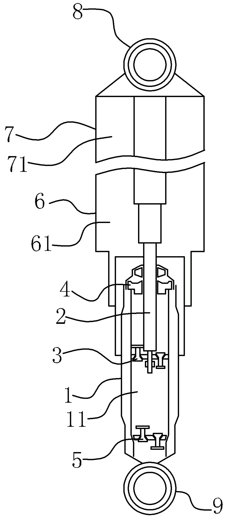
图1是本汽车减震器最短长度状态下的结构示意图。Fig. 1 is a structural schematic diagram of the automobile shock absorber in the shortest length state.
图2是本汽车减震器中间长度状态下的结构示意图。Fig. 2 is a structural schematic diagram of the automobile shock absorber in the middle length state.
图3是本汽车减震器最大长度状态下的结构示意图。Fig. 3 is a structural schematic diagram of the automobile shock absorber in a state of maximum length.
图4是背景技术中减震器的结构示意图。Fig. 4 is a schematic structural diagram of a shock absorber in the background technology.
图中,1、壳体一;11、液压腔一;2、活塞杆;3、油封;4、顶阀;5、底阀;6、壳体二;61、液压腔二;7、壳体三;71、液压腔三;8、连接圈一;9、连接圈二。In the figure, 1, shell one; 11, hydraulic chamber one; 2, piston rod; 3, oil seal; 4, top valve; 5, bottom valve; 6, shell two; 61, hydraulic chamber two; 7, shell Three; 71, three hydraulic chambers; 8, one connecting ring; 9, two connecting rings.
具体实施方式Detailed ways
以下是本实用新型的具体实施例并结合附图,对本实用新型的技术方案作进一步的描述,但本实用新型并不限于这些实施例。The following are specific embodiments of the utility model and in conjunction with the accompanying drawings, the technical solution of the utility model is further described, but the utility model is not limited to these embodiments.
如图1、图2和图3所示,本汽车减震器,包括内部具有液压腔一11的壳体一1、活塞杆2、油封3、顶阀4和底阀5,所述的顶阀4设置在液压腔一11的顶部,所述的底阀5设置在液压腔一11的底部,所述的油封3设置在液压腔一11内,所述的活塞杆2一端与上述的油封3相固连,另一端穿出上述的顶阀4,所述的壳体一1外侧套设有壳体二6,且所述的壳体二6能沿着上述的壳体一1上下滑动,所述的壳体二6内部具有液压腔二61,上述的活塞杆2穿过壳体二6的液压腔二61,所述的壳体二6的外侧还套设有能沿着壳体二6上下滑动的壳体三7,所述的壳体三7内部具有液压腔三71,上述的活塞杆2穿出壳体二6进入到壳体三7的液压腔三71内。As shown in Fig. 1, Fig. 2 and Fig. 3, the automobile shock absorber includes a housing 1 with a
在壳体三7上固定有连接圈一8,所述的壳体一1上固定有连接圈二9。通过连接圈一8方便壳体三7与传力装置相连,通过连接圈二9,方便壳体一1与弹性元件相连。A connecting ring one 8 is fixed on the shell three 7 , and a connecting ring two 9 is fixed on the shell one 1 . Through the connecting ring one 8, the shell three 7 is connected with the force transmission device conveniently, and through the connecting ring two 9, the shell one 1 is connected with the elastic element conveniently.
在本实施例中,壳体一1、壳体二6和壳体三7采用不锈钢材料制成,通过不锈钢材料制成的壳体一1、壳体二6和壳体大大的提高了本汽车减震器的使用寿命。In this embodiment, housing one 1, housing two 6 and housing three 7 are made of stainless steel, and the housing one 1, housing two 6 and housing made of stainless steel greatly improve the performance of the automobile. The service life of the shock absorber.
本汽车减震器是用来作为汽车悬架的重要部件,本汽车减震器的壳体一1的连接圈二9是与弹性元件相连的,壳体三7的连接圈一8是与传力装置相连的。汽车在行驶过程中,壳体一1缩入到壳体二6内,壳体二6也可以缩入到壳体三7内,满足车主在市区驾车需降低车辆底盘或野外驾车需升高的底盘的需要。The automobile shock absorber is used as an important part of the automobile suspension. The connecting
本文中所描述的具体实施例仅仅是对本实用新型精神作举例说明。本实用新型所属技术领域的技术人员可以对所描述的具体实施例做各种各样的修改或补充或采用类似的方式替代,但并不会偏离本实用新型的精神或者超越所附权利要求书所定义的范围。The specific embodiments described herein are only examples to illustrate the spirit of the present invention. Those skilled in the technical field to which the utility model belongs can make various modifications or supplements to the described specific embodiments or adopt similar methods to replace them, but they will not deviate from the spirit of the utility model or go beyond the appended claims defined range.
尽管本文较多地使用了1、壳体一;11、液压腔一;2、活塞杆;3、油封;4、顶阀;5、底阀;6、壳体二;61、液压腔二;7、壳体三;71、液压腔三;8、连接圈一;9、连接圈二等术语,但并不排除使用其它术语的可能性。使用这些术语仅仅是为了更方便地描述和解释本实用新型的本质;把它们解释成任何一种附加的限制都是与本实用新型精神相违背的。Although this article uses 1, shell one; 11, hydraulic chamber one; 2, piston rod; 3, oil seal; 4, top valve; 5, bottom valve; 6, shell two; 61, hydraulic chamber two; 7. Shell three; 71. Hydraulic chamber three; 8. Connection ring one; 9. Connection ring two and other terms, but the possibility of using other terms is not excluded. These terms are only used to describe and explain the essence of the utility model more conveniently; interpreting them as any kind of additional limitation is contrary to the spirit of the utility model.
Claims (3)
Priority Applications (1)
| Application Number | Priority Date | Filing Date | Title |
|---|---|---|---|
| CN2010206676941U CN201916411U (en) | 2010-12-20 | 2010-12-20 | Automobile shock absorber |
Applications Claiming Priority (1)
| Application Number | Priority Date | Filing Date | Title |
|---|---|---|---|
| CN2010206676941U CN201916411U (en) | 2010-12-20 | 2010-12-20 | Automobile shock absorber |
Publications (1)
| Publication Number | Publication Date |
|---|---|
| CN201916411U true CN201916411U (en) | 2011-08-03 |
Family
ID=44416208
Family Applications (1)
| Application Number | Title | Priority Date | Filing Date |
|---|---|---|---|
| CN2010206676941U Expired - Fee Related CN201916411U (en) | 2010-12-20 | 2010-12-20 | Automobile shock absorber |
Country Status (1)
| Country | Link |
|---|---|
| CN (1) | CN201916411U (en) |
Cited By (1)
| Publication number | Priority date | Publication date | Assignee | Title |
|---|---|---|---|---|
| CN106641075A (en) * | 2016-11-30 | 2017-05-10 | 江西洪都航空工业集团有限责任公司 | Two-stage air cock type buffer |
-
2010
- 2010-12-20 CN CN2010206676941U patent/CN201916411U/en not_active Expired - Fee Related
Cited By (2)
| Publication number | Priority date | Publication date | Assignee | Title |
|---|---|---|---|---|
| CN106641075A (en) * | 2016-11-30 | 2017-05-10 | 江西洪都航空工业集团有限责任公司 | Two-stage air cock type buffer |
| CN106641075B (en) * | 2016-11-30 | 2019-03-29 | 江西洪都航空工业集团有限责任公司 | A kind of two-stage vent plug formula buffer |
Similar Documents
| Publication | Publication Date | Title |
|---|---|---|
| CN2811665Y (en) | Single-chamber oil-gas separation type oil-gas spring with nonlinear characteristics | |
| CN103802626A (en) | Vehicle suspension system | |
| CN204284289U (en) | A kind of amplitude selects vibration damper | |
| CN212272918U (en) | Double-spring shock absorber | |
| CN105644289A (en) | Novel passive suspension comprising inertial container | |
| CN201273355Y (en) | Self-protecting variable-damping hydraulic buffer | |
| CN201236918Y (en) | Magnetic variable-stiffness coil spring apparatus for automotive suspension | |
| CN203146692U (en) | Rear shock absorber with two springs | |
| CN201916411U (en) | Automobile shock absorber | |
| CN101323236B (en) | Magnetic Variable Stiffness Suspension Spring Device | |
| CN205468382U (en) | Contains novel passive suspension who is used to container | |
| CN102996696A (en) | Rear suspension oil cylinder for heavy-duty industrial mining vehicle | |
| CN202955172U (en) | Shock absorber | |
| CN205689664U (en) | A kind of vibroshock of band compression buffering | |
| CN202946600U (en) | Vibration isolation block of automobile shock absorber | |
| CN108819608B (en) | A design method for a wheeled vehicle with a driving system without suspension structure | |
| CN206841438U (en) | A kind of train damping device based on multi-stage gear | |
| CN201184386Y (en) | Bidirectional damping variable damper | |
| CN206159355U (en) | Automobile shock absorber ware with buffer gear | |
| CN204061701U (en) | A kind of composite automobile vibration damper | |
| CN203161960U (en) | Multi-spring combined shock absorber | |
| CN202301721U (en) | Strut vibration absorber | |
| CN104315074B (en) | Offroad vehicle three spring dampers | |
| CN204083030U (en) | A kind of hydraulic buffer vibration-damper | |
| CN202413968U (en) | Cab rear suspension of high-motility off-road vehicle |
Legal Events
| Date | Code | Title | Description |
|---|---|---|---|
| C14 | Grant of patent or utility model | ||
| GR01 | Patent grant | ||
| C17 | Cessation of patent right | ||
| CF01 | Termination of patent right due to non-payment of annual fee |
Granted publication date: 20110803 Termination date: 20131220 |