CN202004255U - Electric connector - Google Patents

Electric connector Download PDF

Info

Publication number
CN202004255U
CN202004255U CN2010206190416U CN201020619041U CN202004255U CN 202004255 U CN202004255 U CN 202004255U CN 2010206190416 U CN2010206190416 U CN 2010206190416U CN 201020619041 U CN201020619041 U CN 201020619041U CN 202004255 U CN202004255 U CN 202004255U
Authority
CN
China
Prior art keywords
side wall
terminal
wall
electrical connector
hook
Prior art date
Legal status (The legal status is an assumption and is not a legal conclusion. Google has not performed a legal analysis and makes no representation as to the accuracy of the status listed.)
Expired - Fee Related
Application number
CN2010206190416U
Other languages
Chinese (zh)
Inventor
段云涛
Current Assignee (The listed assignees may be inaccurate. Google has not performed a legal analysis and makes no representation or warranty as to the accuracy of the list.)
Foxconn Kunshan Computer Connector Co Ltd
Hon Hai Precision Industry Co Ltd
Original Assignee
Foxconn Kunshan Computer Connector Co Ltd
Hon Hai Precision Industry Co Ltd
Priority date (The priority date is an assumption and is not a legal conclusion. Google has not performed a legal analysis and makes no representation as to the accuracy of the date listed.)
Filing date
Publication date
Application filed by Foxconn Kunshan Computer Connector Co Ltd, Hon Hai Precision Industry Co Ltd filed Critical Foxconn Kunshan Computer Connector Co Ltd
Priority to CN2010206190416U priority Critical patent/CN202004255U/en
Application granted granted Critical
Publication of CN202004255U publication Critical patent/CN202004255U/en
Anticipated expiration legal-status Critical
Expired - Fee Related legal-status Critical Current

Links

Images

Landscapes

  • Details Of Connecting Devices For Male And Female Coupling (AREA)

Abstract

The invention relates to an electric connector, comprising a shielding shell, a first side wall and a second side wall arranged adjacent and vertical with each other. The fist side wall is equipped with a hook, so is the second side wall; the hook of the first side wall is supported against the outer surface of the second side wall, and the hook of the second side wall is supported against the outer surface of the first side wall, so that the first side wall and the second side wall are combined together. The electric connector is simple in structure, stable in cooperation and convenient in operation.

Description

电连接器electrical connector

【技术领域】【Technical field】

本实用新型涉及一种电连接器,尤其涉及所述电连接器的遮蔽壳体的卡扣配合结构。The utility model relates to an electric connector, in particular to a snap fit structure of a shielding shell of the electric connector.

【背景技术】【Background technique】

现有技术中,传统连接器的遮蔽壳体通常将其结合的位置设置为交错排布的双燕尾结构,即将遮蔽壳体结合的第一部分设置若干相间隔开凹口,凹口之间设有突出部,另一部分对应凹口设有与凹口形状相同的突出部,对应突出部设有与突出部形状相同的凹口,第二部分的突出部收容在第一部分的凹口内并与凹口卡持配合,第一部分的突出部收容在第二部分的凹口内并与凹口卡持配合,二者结合从而将遮蔽壳体的两部分结合在一起。但是,该种传统的结构在组装的过程中易分离而需要焊接,因此,需要对现有技术进行改进,以能够克服上述缺陷。In the prior art, the shielding shells of traditional connectors usually set their combined positions in a staggered double dovetail structure, that is, the first part where the shielding shells are combined is provided with a number of notches spaced apart from each other, and there are gaps between the notches. Protrusion, the other part corresponding to the notch is provided with a protruding part with the same shape as the notch, and the corresponding protruding part is provided with a notch with the same shape as the protruding part. snap fit, the protruding part of the first part is accommodated in the notch of the second part and snap fit with the notch, and the two are combined to combine the two parts of the shielding shell together. However, this traditional structure is easy to be separated during the assembly process and needs to be welded. Therefore, it is necessary to improve the prior art to overcome the above-mentioned defects.

【实用新型内容】【Content of utility model】

本实用新型所要解决的技术问题在于提供一种遮蔽壳体的配合稳定、结构简单的电连接器。The technical problem to be solved by the utility model is to provide an electric connector with a stable matching of the shielding shell and a simple structure.

为解决上述技术问题,本实用新型可采用以下技术方案:一种电连接器,其包括一遮蔽壳体,其具有相邻且相互垂直设置的第一、第二侧壁,所述第一侧壁设有弯钩,第二侧壁亦设有弯钩,所述第一侧壁的弯钩抵持在第二侧壁的外表面,第二侧壁的弯钩抵持在第一侧壁的外表面而将第一侧壁与第二侧壁结合在一起。In order to solve the above technical problems, the utility model can adopt the following technical solutions: an electrical connector, which includes a shielding shell, which has first and second side walls that are adjacent and perpendicular to each other, and the first side The wall is provided with a hook, and the second side wall is also provided with a hook. The hook of the first side wall is against the outer surface of the second side wall, and the hook of the second side wall is against the first side wall. The outer surface of the first side wall and the second side wall are combined together.

与现有技术相比,本实用新型具有如下有益效果:相对于现有技术,本实用新型电连接器的遮蔽壳体通过在相邻的两个侧壁上设置弯钩,其中一侧壁的弯钩抵持在另一侧壁上而相互结合,配合稳定,结构简单,操作方便。Compared with the prior art, the utility model has the following beneficial effects: Compared with the prior art, the shielding shell of the electrical connector of the utility model is provided with hooks on two adjacent side walls, wherein the side walls The hooks are held against the other side wall to combine with each other, the cooperation is stable, the structure is simple, and the operation is convenient.

【附图说明】【Description of drawings】

图1为本实用新型电连接器的立体图;Fig. 1 is a perspective view of the utility model electrical connector;

图2为图1所示电连接器的部分分解图;Fig. 2 is a partial exploded view of the electrical connector shown in Fig. 1;

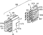
图3为图2所示电连接器的绝缘本体与端子模组的分解图;Fig. 3 is an exploded view of the insulating body and the terminal module of the electrical connector shown in Fig. 2;

图4为图2所示电连接器的端子模组的分解图;FIG. 4 is an exploded view of the terminal module of the electrical connector shown in FIG. 2;

图5为本实用新型电连接器另一角度的立体图;Fig. 5 is a perspective view of another angle of the electrical connector of the present invention;

图6为图5所示电连接器的部分分解图;Fig. 6 is a partially exploded view of the electrical connector shown in Fig. 5;

图7为本实用新型电连接器第三角度的立体图;7 is a perspective view of a third angle of the electrical connector of the present invention;

图8为图7所示电连接器的遮蔽壳体的立体图。FIG. 8 is a perspective view of the shielding shell of the electrical connector shown in FIG. 7 .

【主要组件符号说明】[Description of main component symbols]

电连接器      100        色缘本体              1Electrical connector 100 chrome body 1

底壁          10         卡槽                  101Bottom wall 10 Card slot 101

底开口        103        主体                  11Bottom opening 103 Main body 11

收容腔        110        延伸壁                12Containment Chamber 110 Extension Wall 12

舌板          13         侧面                  131Tongue plate 13 side 131

第二端子槽    133        间隙                  14Second terminal slot 133 Clearance 14

左侧壁        15         左侧壁端子槽          151Left side wall 15 Left side wall terminal slot 151

右侧壁        17         右侧壁端子槽          171Right side wall 17 Right side wall terminal slot 171

凸部          153、173   狭槽                  155、175Convex 153, 173 Slot 155, 175

顶壁          19         开槽                  191Top wall 19 Slotted 191

端子模组      3          色缘体                31Terminal Module 3 Color Body 31

导电端子      33         安装部                331Conductive terminal 33 Installation part 331

水平安装部    331a       垂直安装部            331bHorizontal installation part 331a Vertical installation part 331b

对接部        333        焊接部                335Docking part 333 Welding part 335

夹持开口      337        端子载体              35Clamping Opening 337 Terminal Carrier 35

载体左侧      351        载体右侧              353Left side of carrier 351 Right side of carrier 353

第一端子槽    355        卡块                  357The first terminal slot 355 card block 357

隔栏          359        卡扣机构              37Barrier 359 Buckle Mechanism 37

连接部        371        卡扣凸块              373Connecting part 371 Buckle bump 373

开口          375        连接臂                377opening 375 connecting arm 377

遮蔽壳体      5          壳顶壁                51Shielding Shell 5 Shell Top Wall 51

开孔          511        第一、第四侧壁(壳侧壁)53Hole 511 The first and fourth side walls (shell side walls) 53

凹口            531    第一弯钩    533Notch 531 First hook 533

第二侧壁(壳底壁)55     第二弯钩    551Second side wall (shell bottom wall) 55 Second crotch 551

第三侧壁(导引壁)57The third side wall (guide wall) 57

【具体实施方式】【Detailed ways】

请参阅图1至8所示为符合本实用新型的电连接器100,其用于安装至一外部设备,比如电路板上。所述电连接器100包括绝缘本体1、端子模组3及遮蔽壳体5。Please refer to FIGS. 1 to 8 which show an electrical connector 100 according to the present invention, which is used to be installed on an external device, such as a circuit board. The electrical connector 100 includes an insulating body 1 , a terminal module 3 and a shielding case 5 .

请参阅图3、4和6所示,所述绝缘本体1设有具有收容腔110的主体11及自主体11向前延伸形成的舌板13。所述主体11具有相对设置的左侧壁15、右侧壁17、连接左侧壁15与右侧壁17的顶壁19及底壁10,所述左侧壁15、右侧壁17、顶壁19与底壁10共同围成所述收容腔110。Referring to FIGS. 3 , 4 and 6 , the insulating body 1 is provided with a main body 11 having a receiving cavity 110 and a tongue 13 extending forward from the main body 11 . The main body 11 has a left side wall 15, a right side wall 17, a top wall 19 and a bottom wall 10 connecting the left side wall 15 and the right side wall 17, the left side wall 15, the right side wall 17, the top The wall 19 and the bottom wall 10 together define the receiving cavity 110 .

所述主体11的顶壁19在其后端设有开槽191。左侧壁15在其内侧设有平行间隔的四个左侧壁端子槽151,右侧壁17在其内侧设有平行间隔的五个右侧壁端子槽171。该等左侧壁端子槽151与右侧壁端子槽171平行于底壁10水平设置。所述左、右侧壁15、17在其连接底壁10的位置各设有一平行于底壁10的卡槽101。所述左、右侧壁15、17各自在其外侧向外延伸设有一凸部153、173,所述凸部153、173与左、右侧壁15、17之间形成一对狭槽155、175。所述底壁10自后向前开设有一连通收容腔110的底开口103,且底壁10向前延伸超出主体11的前端面形成一延伸壁12,所述延伸壁12与舌板13的下方之间具有一间隙14。The top wall 19 of the main body 11 defines a slot 191 at a rear end thereof. The left side wall 15 is provided with four left side wall terminal slots 151 parallel and spaced on its inner side, and the right side wall 17 is provided with five right side wall terminal slots 171 parallel spaced on its inner side. The terminal grooves 151 on the left side wall and the terminal grooves 171 on the right side wall are horizontally disposed parallel to the bottom wall 10 . The left and right side walls 15 , 17 are respectively provided with a locking groove 101 parallel to the bottom wall 10 at the positions where they connect to the bottom wall 10 . The left and right side walls 15, 17 are respectively provided with a convex portion 153, 173 extending outward on the outer side thereof, and a pair of slots 155, 155 are formed between the convex portion 153, 173 and the left and right side walls 15, 17. 175. The bottom wall 10 is provided with a bottom opening 103 communicating with the receiving cavity 110 from the rear to the front, and the bottom wall 10 extends forward beyond the front end of the main body 11 to form an extension wall 12 , the extension wall 12 is connected to the bottom of the tongue plate 13 There is a gap 14 between them.

所述舌板13具有相反的两侧面131,其中一侧面131对应左侧壁15的四个左侧壁端子槽151设有四个第二端子槽133,另一侧面131对应右侧壁17的五个右侧壁端子槽171设有五个第二端子槽133,该等第二端子槽133与收容腔110连通设置。The tongue plate 13 has two opposite sides 131, wherein one side 131 is provided with four second terminal slots 133 corresponding to the four left side wall terminal grooves 151 of the left side wall 15, and the other side 131 is corresponding to the right side wall 17. The five terminal slots 171 on the right side wall are provided with five second terminal slots 133 , and the second terminal slots 133 are communicated with the receiving cavity 110 .

请参阅图3、4和6所示,所述端子模组3安装在绝缘本体1内,其包括绝缘体31及组装在绝缘体31内的若干导电端子33。Please refer to FIGS. 3 , 4 and 6 , the terminal module 3 is installed in the insulating body 1 , and includes an insulator 31 and a plurality of conductive terminals 33 assembled in the insulator 31 .

绝缘体31具有端子载体35及设置在端子载体35上方的卡扣机构37。所述端子载体35具有相反设置的载体左侧351和载体右侧353,载体左侧351具有四个平行间隔设置的第一端子槽355,载体右侧353具有五个平行间隔设置的第一端子槽355,各第一端子槽355具有相互连通的水平槽与竖直槽,所述相邻第一端子槽355之间设有隔栏359。The insulator 31 has a terminal carrier 35 and a buckle mechanism 37 disposed above the terminal carrier 35 . The terminal carrier 35 has a carrier left side 351 and a carrier right side 353 arranged oppositely, the carrier left side 351 has four first terminal grooves 355 arranged in parallel and spaced apart, and the carrier right side 353 has five first terminals arranged in parallel and spaced apart. Slots 355 , each first terminal slot 355 has a horizontal slot and a vertical slot communicating with each other, and a barrier 359 is provided between the adjacent first terminal slots 355 .

所述卡扣机构37设置在绝缘体31的上方,用于与遮蔽壳体5卡扣配合。所述卡扣机构37具有连接部371及设置在连接部371上方的卡扣凸块373。所述连接部371的中间部分设有开口375,该开口375使得连接部371呈中空状,连接部371围绕开口375的周围形成连接臂377,所述卡扣凸块373设置在连接臂377上。The buckle mechanism 37 is arranged above the insulator 31 and is used for snap fit with the shielding case 5 . The locking mechanism 37 has a connecting portion 371 and a locking protrusion 373 disposed above the connecting portion 371 . The middle part of the connecting portion 371 is provided with an opening 375, the opening 375 makes the connecting portion 371 hollow, the connecting portion 371 forms a connecting arm 377 around the opening 375, and the buckle protrusion 373 is arranged on the connecting arm 377 .

所述绝缘体31的端子载体35收容在绝缘本体1的收容腔110内,卡扣机构37的连接部371收容在绝缘本体1顶壁19的开槽191内,卡扣凸块373则延伸出顶壁19的上侧面,即卡扣凸块373延伸出绝缘本体侧壁。所述绝缘体31在其外侧设有卡块357,所述卡块357干涉配合收容在绝缘本体1的卡槽101内从而将端子模组3固定在绝缘本体1的收容腔110内。The terminal carrier 35 of the insulator 31 is accommodated in the accommodation cavity 110 of the insulator body 1, the connecting portion 371 of the buckle mechanism 37 is accommodated in the slot 191 of the top wall 19 of the insulator body 1, and the buckle protrusion 373 extends out of the top. The upper side of the wall 19 , that is, the locking protrusion 373 extends out of the side wall of the insulating body. The insulator 31 is provided with a locking block 357 on its outer side, and the locking block 357 is accommodated in the slot 101 of the insulating body 1 through interference fit so as to fix the terminal module 3 in the receiving cavity 110 of the insulating body 1 .

所述导电端子33具有安装部331、自安装部331的一端延伸形成的对接部333及安装部331的另一端延伸形成的焊接部335。所述安装部331设有水平的水平安装部331a及垂直于水平安装部331a的垂直安装部331b。所述若干导电端子33共有九根,其中第一至八根导电端子33的形状及结构均相同,第九根导电端子33的对接部333的宽度小于其它导电端子,安装部331自水平安装部331a平行于垂直安装部331b延伸设有一延伸部331c,所述延伸部331c与垂直安装部331b同向延伸从而形成一夹持开口337。其中第一至四根导电端子33干涉配合收容在载体左侧351的第一端子槽355内,第五至九根导电端子33干涉配合收容在载体右侧353的第一端子槽355内。其中,各导电端子33的水平安装部331a收容在第一端子槽355的水平槽内,垂直安装部331b收容在第一端子槽355的垂直槽内,对接部333通过绝缘本体1内左侧壁端子槽151和右侧壁端子槽171的导引延伸出水平槽并收容在绝缘本体1舌板的第二端子槽133内,以便于与对接连接器配合连接,焊接部335延伸出垂直槽。第九根导电端子的夹持开口337夹持在端子载体35的隔栏359上,即隔栏359卡持在延伸部331c与垂直安装部331b之间,此时,导电端子33被稳定的固持在端子载体35上。The conductive terminal 33 has a mounting portion 331 , a mating portion 333 extending from one end of the mounting portion 331 , and a welding portion 335 extending from the other end of the mounting portion 331 . The mounting portion 331 has a horizontal mounting portion 331a and a vertical mounting portion 331b perpendicular to the horizontal mounting portion 331a. The plurality of conductive terminals 33 have nine in total, wherein the shapes and structures of the first to eight conductive terminals 33 are the same, the width of the butt joint portion 333 of the ninth conductive terminal 33 is smaller than that of other conductive terminals, and the mounting portion 331 is formed from the horizontal mounting portion. An extending portion 331c extends parallel to the vertical mounting portion 331b from the 331a, and the extending portion 331c extends in the same direction as the vertical mounting portion 331b to form a clamping opening 337 . The first to fourth conductive terminals 33 are received in the first terminal slot 355 of the left side 351 of the carrier with interference fit, and the fifth to ninth conductive terminals 33 are received in the first terminal slot 355 of the right side 353 of the carrier with interference fit. Wherein, the horizontal mounting portion 331a of each conductive terminal 33 is accommodated in the horizontal groove of the first terminal groove 355, the vertical mounting portion 331b is accommodated in the vertical groove of the first terminal groove 355, and the abutting portion 333 passes through the left side wall of the insulating body 1. The guides of the terminal groove 151 and the terminal groove 171 on the right side wall extend out of the horizontal groove and are accommodated in the second terminal groove 133 of the tongue plate of the insulating body 1 for mating connection with the mating connector. The welding part 335 extends out of the vertical groove. The clamping opening 337 of the ninth conductive terminal is clamped on the barrier 359 of the terminal carrier 35, that is, the barrier 359 is clamped between the extension part 331c and the vertical mounting part 331b. At this time, the conductive terminal 33 is held stably on the terminal carrier 35 .

所述端子模组3自后向前安装至绝缘本体1,此时,端子载体35收容在绝缘本体1的收容腔110内,端子载体35两侧的卡块357干涉配合收容在绝缘本体1的卡槽101内从而将端子模组3固定在绝缘本体1的收容腔110内。卡扣机构37的连接部371收容在主体11的顶壁19的开槽191内,卡扣凸块373延伸超出顶壁19的上端面而位于顶壁19的上方。各导电端子33的对接部333通过绝缘本体1主体11内壁的左侧壁端子槽151和右侧壁端子槽171的导引最终收容在舌板的 第二端子槽133内,以便与对接连接器(未图示)的导电端子配合连接,焊接部335自主体11底壁10的底开口103延伸出绝缘本体1以便于焊接至外部设备。The terminal module 3 is installed on the insulating body 1 from the back to the front. At this time, the terminal carrier 35 is accommodated in the receiving cavity 110 of the insulating body 1, and the blocks 357 on both sides of the terminal carrier 35 are interference-fitted and accommodated in the insulating body 1. The slot 101 is used to fix the terminal module 3 in the receiving cavity 110 of the insulating housing 1 . The connecting portion 371 of the locking mechanism 37 is received in the slot 191 of the top wall 19 of the main body 11 , and the locking protrusion 373 extends beyond the upper surface of the top wall 19 and is located above the top wall 19 . The butt joint portion 333 of each conductive terminal 33 is finally accommodated in the second terminal groove 133 of the tongue plate through the guidance of the left side wall terminal groove 151 and the right side wall terminal groove 171 of the inner wall of the main body 11 of the insulating body 1, so as to be connected with the docking connector. The conductive terminals (not shown) are mated and connected, and the welding portion 335 extends out of the insulating body 1 from the bottom opening 103 of the bottom wall 10 of the main body 11 to facilitate welding to external devices.

所述遮蔽壳体5设有第一侧壁53、垂直并连接于第一侧壁53的壳顶壁51、连接壳顶壁51并倾斜设置的第三侧壁57、连接于第三侧壁57并平行于第一侧壁53的第四侧壁53,所述第二侧壁55的一端连接于第四侧壁53,另一端通过弯钩551与第一侧壁抵持连接,从而与第一侧壁53、壳顶壁51、第三侧壁57和第四侧壁53共同围成一完整的遮蔽壳体5。第一侧壁53和第四侧壁53在本实施例的描述中即相对设置的一对壳侧壁53,第三侧壁57即导引壁57。即该遮蔽壳体5设有壳顶壁51、垂直于壳顶壁51并相对设置的一对壳侧壁53、平行于壳顶壁51并连接于一对壳侧壁53的壳底壁55及连接壳顶壁51与壳侧壁53的导引壁57,壳侧壁53和壳底壁55相邻设置。所述壳顶壁51在其后方设有开孔511,每一壳侧壁53在其后方设有凹口531,且其中一壳侧壁53在邻接壳底壁55的位置具有相互间隔设置的一对第一弯钩533,该等第一弯钩533垂直于壳侧壁53并平行于壳底壁55,壳底壁55在邻接壳侧壁51的位置设有一第二弯钩551,该第二弯钩551垂直于壳底壁55并平行于壳侧壁53。所述第一弯钩533抵持在壳底壁55的外表面,壳底壁55的第二弯钩551抵持在壳侧壁53的外表面,且第二弯钩551位于第一弯钩533之间从而将壳侧壁53和壳底壁55稳定结合在一起,配合稳定,结构简单,操作方便。所述导引壁57呈斜面设置,该斜面用于导引对接连接器插入即防止对接连接器的误插。The shielding housing 5 is provided with a first side wall 53, a shell top wall 51 perpendicular to and connected to the first side wall 53, a third side wall 57 connected to the shell top wall 51 and obliquely arranged, connected to the third side wall 57 and parallel to the fourth side wall 53 of the first side wall 53, one end of the second side wall 55 is connected to the fourth side wall 53, and the other end is connected to the first side wall through the hook 551, so as to be connected with The first side wall 53 , the housing top wall 51 , the third side wall 57 and the fourth side wall 53 together form a complete shielding housing 5 . In the description of this embodiment, the first side wall 53 and the fourth side wall 53 are a pair of housing side walls 53 oppositely arranged, and the third side wall 57 is a guide wall 57 . That is, the shielding housing 5 is provided with a shell top wall 51, a pair of shell side walls 53 perpendicular to the shell top wall 51 and oppositely arranged, and a shell bottom wall 55 parallel to the shell top wall 51 and connected to the pair of shell side walls 53. And the guide wall 57 connecting the shell top wall 51 and the shell side wall 53, the shell side wall 53 and the shell bottom wall 55 are adjacently arranged. The top wall 51 of the case is provided with an opening 511 at its rear, and each side wall 53 of the case is provided with a notch 531 at its rear, and one of the side walls 53 of the case has gaps arranged at intervals at a position adjacent to the bottom wall 55 of the case. A pair of first curved hooks 533, these first curved hooks 533 are perpendicular to the shell side wall 53 and parallel to the shell bottom wall 55, the shell bottom wall 55 is provided with a second curved hook 551 at the position adjacent to the shell side wall 51, the The second hook 551 is perpendicular to the bottom wall 55 of the case and parallel to the side wall 53 of the case. The first hook 533 is against the outer surface of the case bottom wall 55, the second hook 551 of the case bottom wall 55 is against the outer surface of the case side wall 53, and the second hook 551 is located on the first hook. 533 so that the shell side wall 53 and the shell bottom wall 55 are stably combined together, the cooperation is stable, the structure is simple, and the operation is convenient. The guide wall 57 is provided with an inclined plane, and the inclined plane is used to guide the insertion of the butt connector, that is, to prevent mis-insertion of the butt connector.

请参阅图1、2、7和8所示,所述遮蔽壳体5包覆在绝缘本体1与端子模组3外围时,绝缘本体1的主体11的左、右侧壁15、17的凸部153、173,卡持在壳侧壁53的凹口531内,此时,壳侧壁53在其位于凹口531的边缘干涉配合收容在凸部153、173与左、右侧壁15、17之间形成的狭槽155、175内,从而将遮蔽壳体5上下定位在绝缘本体1的外围。端子模组3的绝缘体31的卡扣机构37的卡扣凸块373卡持收容在壳顶壁51的开孔511内,从而防止遮蔽壳体5在绝缘本体1上的前后晃动,所述开口375为卡扣凸块373收容进遮蔽壳体5的开孔内时提供形变空间,该开口375使得卡扣机构37在组装时插入力小,组装劳动强度小,装配简单,且卡扣机构37的卡扣凸块373的结构弹性良好,在卡扣导开孔511内时可回弹,不易损坏。壳底壁55后端收容在绝缘本体1的间隙14内,使得壳底壁55位于延伸壁12与舌板13之间,从而防止遮蔽壳体5上下移动。Please refer to Figures 1, 2, 7 and 8, when the shielding housing 5 is wrapped around the periphery of the insulating body 1 and the terminal module 3, the protrusions of the left and right side walls 15, 17 of the main body 11 of the insulating body 1 Parts 153, 173 are clamped in the notch 531 of the side wall 53 of the case. At this time, the side wall 53 of the case is accommodated in the convex part 153, 173 and the left and right side walls 15, 15, 17 formed between the slots 155, 175, so that the shielding shell 5 is positioned on the periphery of the insulating body 1 up and down. The buckle projection 373 of the buckle mechanism 37 of the insulator 31 of the terminal module 3 is locked and accommodated in the opening 511 of the top wall 51 of the housing, thereby preventing the shielding housing 5 from shaking back and forth on the insulation body 1. The opening 375 provides a space for deformation when the buckle projection 373 is accommodated in the opening of the shielding housing 5. The opening 375 makes the insertion force of the buckle mechanism 37 small during assembly, the assembly labor intensity is small, and the assembly is simple, and the buckle mechanism 37 The buckle protrusion 373 has good structural elasticity, can rebound when it is in the buckle guide hole 511, and is not easy to be damaged. The rear end of the housing bottom wall 55 is accommodated in the gap 14 of the insulating body 1 , so that the housing bottom wall 55 is located between the extension wall 12 and the tongue plate 13 , thereby preventing the shielding housing 5 from moving up and down.

本实用新型电连接器100为一种特殊的可传输电源的USB连接器,该 电连接器100便于拆解,结构简单,其端子模组3的绝缘体31与遮蔽壳体5的卡扣结构在组装时插入力小,组装劳动强度小且所述卡扣结构弹性良好,在弯钩卡到位时,可回弹。The electrical connector 100 of the utility model is a special USB connector capable of transmitting power. The electrical connector 100 is easy to disassemble and has a simple structure. When assembling, the insertion force is small, the assembling labor intensity is small, and the buckle structure has good elasticity, and can rebound when the hook is locked in place.

Claims (10)

1.一种电连接器,其包括一遮蔽壳体,其具有相邻且相互垂直设置的第一、第二侧壁,其特征在于:所述第一侧壁设有弯钩,第二侧壁亦设有弯钩,所述第一侧壁的弯钩抵持在第二侧壁的外表面,第二侧壁的弯钩抵持在第一侧壁的外表面而将第一侧壁与第二侧壁结合在一起。1. An electrical connector, which includes a shielding housing, which has adjacent and mutually perpendicular first and second side walls, characterized in that: the first side wall is provided with a hook, and the second side wall The wall is also provided with a hook, the hook of the first side wall is against the outer surface of the second side wall, and the hook of the second side wall is against the outer surface of the first side wall so that the first side wall Combined with the second side wall. 2.如权利要求1所述的电连接器,其特征在于:所述第一侧壁的弯钩为相互间隔的一对第一弯钩,第二侧壁的弯钩为一第二弯钩,所述第二侧壁的第二弯钩位于第一侧壁的第一弯钩之间。2. The electrical connector according to claim 1, wherein the hooks of the first side wall are a pair of first hooks spaced apart from each other, and the hooks of the second side wall are a second hook , the second hook of the second side wall is located between the first hooks of the first side wall. 3.如权利要求2所述的电连接器,其特征在于:所述遮蔽壳体还设有垂直并连接于第一侧壁的壳顶壁、连接顶壁并倾斜设置的第三侧壁、连接于第三侧壁并平行于第一侧壁的第四侧壁,所述第二侧壁的一端连接于第四侧壁,另一端通过前述弯钩与第一侧壁抵持连接,从而与第一侧壁、壳顶壁、第三侧壁和第四侧壁共同围成一完整的遮蔽壳体。3. The electrical connector according to claim 2, wherein the shielding housing is further provided with a housing top wall which is vertical and connected to the first side wall, a third side wall connected to the top wall and arranged obliquely, The fourth side wall connected to the third side wall and parallel to the first side wall, one end of the second side wall is connected to the fourth side wall, and the other end is connected to the first side wall through the aforementioned hook, so that Together with the first side wall, the shell top wall, the third side wall and the fourth side wall, a complete shielding shell is formed. 4.如权利要求3所述的电连接器,其特征在于:所述第三侧壁为呈斜面设置的导引壁,该导引壁用以防止对接连接器插入时的误插。4 . The electrical connector according to claim 3 , wherein the third side wall is a guide wall arranged on an inclined plane, and the guide wall is used to prevent mis-insertion when the mating connector is inserted. 5.如权利要求1所述的电连接器,其特征在于:所述电连接器还包括绝缘本体及安装在绝缘本体内的端子模组,所述遮蔽壳体包覆在绝缘本体和端子模组的外围,端子模组包括绝缘体及组装在绝缘体内的若干端子,绝缘体设有与遮蔽壳体配合的卡扣机构,遮蔽壳体设有开孔,该卡扣机构设有卡扣凸块,所述绝缘本体具有相对设置的一对侧壁,所述端子模组卡持收容在所述侧壁之间,卡持凸块延伸出绝缘本体侧壁并卡持收容在遮蔽壳体的开孔内。5. The electrical connector according to claim 1, wherein the electrical connector further comprises an insulating body and a terminal module installed in the insulating body, and the shielding shell covers the insulating body and the terminal module. On the periphery of the group, the terminal module includes an insulator and a number of terminals assembled in the insulator. The insulator is provided with a buckle mechanism that cooperates with the shielding shell. The shielding shell is provided with an opening. The buckle mechanism is provided with a buckle bump. The insulating body has a pair of opposite side walls, the terminal module is clamped and accommodated between the side walls, and the locking protrusion extends out of the side wall of the insulating body and is locked and accommodated in the opening of the shielding case. Inside. 6.如权利要求5所述的电连接器,其特征在于:所述绝缘体还设有端子载体,所述卡扣机构设有位于卡扣凸块与端子载体之间的连接部,所述连接部的中间部分设有开口,开口的周围形成连接臂,所述卡扣凸块设置在所述连接臂上,所述开口为卡扣凸块收容进遮蔽壳体的开孔内时提供形变空间。6. The electrical connector according to claim 5, wherein the insulator is further provided with a terminal carrier, and the buckle mechanism is provided with a connection portion between the buckle bump and the terminal carrier, and the connection The middle part of the part is provided with an opening, and a connecting arm is formed around the opening, and the buckle protrusion is arranged on the connecting arm, and the opening provides a deformation space for the buckle protrusion to be accommodated in the opening of the shielding shell . 7.如权利要求5所述的电连接器,其特征在于:所述绝缘本体还设有连接一对侧壁的顶壁,所述顶壁设有开槽,所述卡扣机构的连接部收容在开槽内,卡持凸块延伸超出顶壁而卡持收容在遮蔽壳体的开孔内。7. The electrical connector according to claim 5, wherein the insulating body is further provided with a top wall connecting a pair of side walls, the top wall is provided with a slot, and the connecting part of the buckle mechanism Received in the slot, the clamping protrusion extends beyond the top wall and is clamped and received in the opening of the shielding shell. 8.如权利要求5所述的电连接器,其特征在于:所述绝缘体具有相反设置的两侧,每一侧具有若干平行间隔设置的第一端子槽,所述导电端子具有安装至第一端子槽的安装部和自安装部的一端延伸形成的对接部,所述安装部收容在所述第一端子槽内,对接部延伸出绝缘体以便于与对接连接器配合连接。8. The electrical connector according to claim 5, wherein the insulator has two opposite sides, and each side has a plurality of first terminal grooves arranged in parallel and spaced apart, and the conductive terminals have a device mounted on the first The mounting part of the terminal groove and the butt joint extending from one end of the mounting part are accommodated in the first terminal groove, and the butt joint extends out of the insulator to facilitate mating connection with the butt connector. 9.如权利要求8所述的电连接器,其特征在于:所述安装部设有水平的水平安装部及垂直于水平安装部的垂直安装部,所述水平安装部平行于垂直安装部延伸设有一延伸部,所述延伸部与垂直安装部同向延伸,所述第一端子槽之间设有隔栏,所述隔栏卡持在延伸部与垂直安装部之间。9. The electrical connector according to claim 8, wherein the mounting portion is provided with a horizontal mounting portion and a vertical mounting portion perpendicular to the horizontal mounting portion, and the horizontal mounting portion extends parallel to the vertical mounting portion An extension part is provided, and the extension part extends in the same direction as the vertical installation part, and a barrier is provided between the first terminal slots, and the barrier is clamped between the extension part and the vertical installation part. 10.如权利要求8所述的电连接器,其特征在于:所述绝缘本体设有主体及自主体向前延伸形成的舌板,所述主体设有位于一对侧壁之间的收容腔,所述舌板设有若干第二端子槽,所述第二端子槽与收容腔连通设置,所述绝缘体收容在收容腔内,所述对接部延伸出收容腔而收容在第二端子槽内。10. The electrical connector according to claim 8, wherein the insulating body is provided with a main body and a tongue plate extending forward from the main body, and the main body is provided with a receiving cavity between a pair of side walls , the tongue plate is provided with a plurality of second terminal slots, the second terminal slots communicate with the receiving cavity, the insulator is stored in the receiving cavity, and the butt joint part extends out of the receiving cavity and is stored in the second terminal slot .
CN2010206190416U 2010-11-23 2010-11-23 Electric connector Expired - Fee Related CN202004255U (en)

Priority Applications (1)

Application Number Priority Date Filing Date Title
CN2010206190416U CN202004255U (en) 2010-11-23 2010-11-23 Electric connector

Applications Claiming Priority (1)

Application Number Priority Date Filing Date Title
CN2010206190416U CN202004255U (en) 2010-11-23 2010-11-23 Electric connector

Publications (1)

Publication Number Publication Date
CN202004255U true CN202004255U (en) 2011-10-05

Family

ID=44706982

Family Applications (1)

Application Number Title Priority Date Filing Date
CN2010206190416U Expired - Fee Related CN202004255U (en) 2010-11-23 2010-11-23 Electric connector

Country Status (1)

Country Link
CN (1) CN202004255U (en)

Cited By (1)

* Cited by examiner, † Cited by third party
Publication number Priority date Publication date Assignee Title
CN112615184A (en) * 2020-12-17 2021-04-06 河南天海电器有限公司 Bent connector and insertion piece thereof

Cited By (1)

* Cited by examiner, † Cited by third party
Publication number Priority date Publication date Assignee Title
CN112615184A (en) * 2020-12-17 2021-04-06 河南天海电器有限公司 Bent connector and insertion piece thereof

Similar Documents

Publication Publication Date Title
US11682865B2 (en) Electric connector and electric connector assembly
CN201397973Y (en) Electric connector
JP4885173B2 (en) Socket connector
CN201323275Y (en) Electric connector
CN102738660B (en) Electric connector and assembly thereof
CN101964470B (en) Electrical connector
CN109103673B (en) Socket connector
CN106936032B (en) Plug connector and plug connector assembly
US20160141817A1 (en) Power connector assembly
US8308513B2 (en) Electrical connector
US8172620B2 (en) Electrical connector assembly
JP2009140923A (en) Electrical connector
CN116231359A (en) electrical connector
CN201708308U (en) Electric connector
CN205355364U (en) Electric connector and patch cable assembly thereof
US8662918B2 (en) Electrical connector
CN201498632U (en) Electrical connector
CN201966389U (en) Electric connector
CN209981537U (en) Electrical connector
JP3202707U (en) Connectors and their terminals
CN209981590U (en) Electrical connector
CN202004255U (en) Electric connector
US12512626B2 (en) Connector and assembly thereof with foolproof structure
CN102738635A (en) Connector and assembly thereof
TWM496878U (en) Electrical connector and electrical connector assembly

Legal Events

Date Code Title Description
C14 Grant of patent or utility model
GR01 Patent grant
CF01 Termination of patent right due to non-payment of annual fee

Granted publication date: 20111005

Termination date: 20141123

EXPY Termination of patent right or utility model