CN202008331U - Check fixture for three-dimensional bending workpiece - Google Patents
Check fixture for three-dimensional bending workpiece Download PDFInfo
- Publication number
- CN202008331U CN202008331U CN2010206812363U CN201020681236U CN202008331U CN 202008331 U CN202008331 U CN 202008331U CN 2010206812363 U CN2010206812363 U CN 2010206812363U CN 201020681236 U CN201020681236 U CN 201020681236U CN 202008331 U CN202008331 U CN 202008331U
- Authority
- CN
- China
- Prior art keywords
- workpiece
- detection
- dimensional bending
- detected
- cubing
- Prior art date
- Legal status (The legal status is an assumption and is not a legal conclusion. Google has not performed a legal analysis and makes no representation as to the accuracy of the status listed.)
- Expired - Lifetime
Links
- 238000005452 bending Methods 0.000 title claims abstract description 44
- 238000001514 detection method Methods 0.000 claims abstract description 102
- 238000010586 diagram Methods 0.000 description 7
- 230000008878 coupling Effects 0.000 description 5
- 238000010168 coupling process Methods 0.000 description 5
- 238000005859 coupling reaction Methods 0.000 description 5
- 230000000007 visual effect Effects 0.000 description 5
- 238000013461 design Methods 0.000 description 3
- 238000011156 evaluation Methods 0.000 description 3
- 230000015572 biosynthetic process Effects 0.000 description 2
- 238000003754 machining Methods 0.000 description 2
- 238000000034 method Methods 0.000 description 2
- 238000005070 sampling Methods 0.000 description 2
- 238000010923 batch production Methods 0.000 description 1
- 230000002950 deficient Effects 0.000 description 1
- 238000003708 edge detection Methods 0.000 description 1
- 230000000694 effects Effects 0.000 description 1
- 238000005516 engineering process Methods 0.000 description 1
- 238000004519 manufacturing process Methods 0.000 description 1
- 238000005259 measurement Methods 0.000 description 1
- 230000007246 mechanism Effects 0.000 description 1
- 238000012545 processing Methods 0.000 description 1
- 238000013214 routine measurement Methods 0.000 description 1
- 210000001364 upper extremity Anatomy 0.000 description 1
- 238000011179 visual inspection Methods 0.000 description 1
- 238000003466 welding Methods 0.000 description 1
Images



Landscapes
- Length Measuring Devices With Unspecified Measuring Means (AREA)
- Bending Of Plates, Rods, And Pipes (AREA)
Abstract
The utility model provides a check fixture for a three-dimensional bending workpiece, which comprises a foundation mounting plate, a plurality of detection vertical plates and at least three positioning blocks, wherein the top surface of the foundation mounting plate can be used as a datum plane for mounting the detection vertical plates and the positioning blocks; the detection vertical plates are sheets arranged on the datum plane and based on the outline of the detected workpiece; the outline of each detection vertical plate is matched with the outline of the surface to be detected of the section of the detected workpiece on a plane on which the detection vertical plate is positioned; each positioning block is provided with a positioning surface matched with a detection positioning surface of the workpiece; and the detected workpiece can be arranged and positioned by depending on the detection of the positioning surface provided by the positioning block. The check fixture for the three-dimensional bending workpiece can be used for conveniently detecting the three-diemsnioan curved surface of the three-dimensional bending workpiece.
Description
Technical field
The utility model relates to detection technique, particularly relates to a kind of cubing that is used for the three-dimensional bending workpiece.
Background technology
In field of machining,, generally adopt appliance special for detecting that the machining precision of its shape is detected for the two-dimentional curved workpieces of producing in batches; But, for the SHAPE DETECTION of space three-dimensional curved workpieces, be difficult to design cubing, so generally adopt general three-dimensional detecting instruments such as laser tracker, three-dimensional to detect.These detection mode dirigibilities are strong, and accuracy of detection is than higher, and still, its equipment cost is very high, and sense cycle is long, the incompatibility batch production requirement.
In view of above reason,, be necessary to design a kind of cubing of its form accuracy of detection that can be fast and convenient for the less demanding three-dimensional bending workpiece of some form accuracies.
The utility model content
Technical problem to be solved in the utility model provides a kind of cubing that is used for the three-dimensional bending workpiece, and this cubing can be checked the three-dimensional form accuracy of workpiece fully easily and fast, is specially adapted to the detection of some three-dimensional bending workpiece that generate in batches.
The utility model provides a kind of cubing that is used for the three-dimensional bending workpiece, comprises a basic installing plate, plurality of detection riser, at least three locating pieces;
Described basic installing plate provides reference field for this cubing;
Described detection riser is that the profile with described detected workpiece serves as according to the thin plate that is arranged on the described reference field, and each detects the appearance profile of riser in the detection position and mates with to be detected the contour shape that this detects the detected workpiece cross section on plane, riser place;
Described locating piece has the locating surface that matches with the detection and location face of workpiece, the location the when locating surface that detected workpiece can rely on locating piece to provide obtains to detect.
Preferably, at each top of detecting riser the radian check-out console is set; The contour curve geometric similarity of the contour curve of this radian check-out console and detected workpiece.
Preferably, several rim detection reference blocks are set on the outer edge surface of described radian check-out console, described rim detection reference block comprises at least one detection plane, this detection plane satisfies following the requirement as the reference field that detects: qualified part is after the locating surface with locating piece is the benchmark location, and the gap between detection plane and the workpiece inner edge surface is in the numerical range of regulation.
Preferably, the edge of described detected workpiece has vertical edge, and described rim detection reference block is L shaped, and is fixed on the corner angle of described radian check-out console, and two limit is detection plane, is respectively applied for the contoured surface that detects detected workpiece body and vertical edge.
Preferably, also comprise a basic skeleton, described basic installing plate is fixed on the basic skeleton.
Preferably, the lateral surface at described detection riser is provided with coaming plate.
Preferably, described detected workpiece is a circular three-dimensional bending workpiece, and has a rib that radially connects the annulus both sides; Described basic installing plate is an annular slab, in the middle of this annular slab the intermediate supports stud is set, and at intermediate supports stud top the intermediate detection installing plate is set; The space radian geometric similarity of the radian of described intermediate detection plate and the rib of described detected workpiece.
Preferably, evenly arrange some intermediate detection reference blocks on the described intermediate detection plate, its upper surface is a detection plane; After the locating surface that detected workpiece provides with locating piece was installed, if this workpiece is qualified workpiece, then the gap between the upper limb face of the lower edge face of detected workpiece and described intermediate detection reference block was in the numerical range of regulation.The cubing that is used for the three-dimensional bending workpiece that the utility model provides, curved shape and detection demand according to concrete detected workpiece, the plurality of detection riser is set on reference field, these detect risers is that profile with described detected workpiece serves as according to the thin plate that is arranged on the described reference field, each detects the appearance profile of riser and to be detected the contour shape coupling in this detected workpiece cross section of detecting plane, riser place, so-called coupling, the appearance profile that promptly should detect riser adopts the shape with to be detected the profile geometric similarity in detected workpiece cross section, but gap slightly on the size.Some locating pieces are set on this cubing simultaneously, and this locating piece has the locating surface that matches with the detection and location face of workpiece, the arrangement location when detected workpiece relies on above-mentioned locating surface to obtain to detect.In this 3 D workpiece, the appearance profile of detection riser is actually the sampling to workpiece curved surface to be detected, and each total appearance profile that detects the common formation of riser constitutes approaching the profile of the three-dimension curved surface to be detected of detected workpiece.After detected workpiece is placed, because the difference on the size, between the outer rim of to be detected of this detected workpiece and described detection riser, form certain clearance, this gap can be by visual inspection, if inconsistent or the gap is obviously excessive, illustrate that then the detected three-dimension curved surface of detected workpiece is defective; If the gap is little, and the gap basically identical of various piece, illustrate that then this three-dimension curved surface is qualified.
In the preferred embodiment, for to be detected the geomery of more accurate assessment three-dimensional bending workpiece and the difference of designing requirement, at above-mentioned detection riser top the radian check-out console is set, whether the extension radian that this radian check-out console can be used to detect the edge of three-dimensional bending workpiece meets the requirements.Further in the preferred version, on described radian check-out console the rim detection reference block is set, this rim detection reference block comprises at least one detection plane, and this detection plane is as the detection reference face.During detection, after the workpiece location, by routine measurement devices such as employing clearance gauges, can measure the gap size between detection reference face and the workpiece inner edge surface, whether the more accurate workpiece of judging meets shape need.
At a kind of specific three-dimensional bending workpiece, promptly circular and have a three-dimensional bending workpiece that is connected the rib of annulus both sides, the utility model provides further preferred embodiment.Particularly, at circular part, the detection riser along the even radial arrangement of annular surface is set, the rib at connecting the annulus both sides then is provided with the intermediate detection plate, the space radian coupling of the radian of this intermediate detection plate and the rib of described detected workpiece.Under the situation of needs, on described intermediate detection plate, the intermediate detection reference block is set, this intermediate detection reference block provides detection plane, and whether the curved surface that is used to detect the rib of described detected workpiece meets processing request.
Description of drawings
Fig. 1 is the workpiece that the cubing that is used for the three-dimensional bending workpiece that the utility model provides need detect;
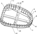
Fig. 2 is the stereoscopic-state synoptic diagram of the cubing that is used for the three-dimensional bending workpiece that provides of the utility model embodiment, and its visual angle is positive;
Fig. 3 is the stereoscopic-state synoptic diagram of the cubing that is used for the three-dimensional bending workpiece that provides of the utility model embodiment, and its visual angle is a reverse side;
Fig. 4 is the constitutional diagram of detected workpiece when detecting on the cubing that the utility model embodiment provides;
Fig. 5 is the sectional view in the A-A cross section of Fig. 4;
Fig. 6 is the sectional view in the B-B cross section of Fig. 4;
Fig. 7 is the sectional view in the C-C cross section of Fig. 4;
Fig. 8 is the sectional view in the D-D cross section of Fig. 4.
Embodiment
Please referring to Fig. 1, the stereographic map of the three-dimensional bending workpiece that this figure provides for the utility model embodiment.This three-dimensional bending workpiece is a circular three-dimensional bending workpiece, and has one and be connected the radially rib of both sides of annulus.Above-mentioned annulus and rib spatially are the three-dimension curved surface form.In addition, the annulus outer rim at this workpiece is provided with the vertical edge of hanging down to the recessed direction of workpiece.
Please referring to Fig. 2, this figure is the stereoscopic-state synoptic diagram of the three-dimensional bending workpiece cubing that provides of present embodiment, and its visual angle is positive; Please be simultaneously referring to Fig. 3, this figure is the stereoscopic-state synoptic diagram of the three-dimensional bending workpiece cubing that provides of present embodiment, its visual angle is a reverse side.Please be simultaneously referring to Fig. 4, this figure be present embodiment provide the actual measurement of three-dimensional bending workpiece cubing the time constitutional diagram.Please be simultaneously referring to Fig. 5, this figure is the sectional view in the A-A cross section of Fig. 4; Please be simultaneously referring to Fig. 6, this figure is the sectional view in the B-B cross section of Fig. 4; Please be simultaneously referring to Fig. 7, this figure is the sectional view in the C-C cross section of Fig. 4; Please be simultaneously referring to Fig. 8, this figure is the sectional view in the D-D cross section of Fig. 4.
As shown in Figures 2 and 3, the cubing of this three-dimensional bending workpiece has a basic skeleton 1, and this basic skeleton 1 provides the shoring of foundation framework for whole cubing, and its structure is according to the global shape needs design of this cubing, in the present embodiment, specifically be middle frame type framework with cross hang.
On above-mentioned basic skeleton 1, be welded with basic installing plate 2 with welding manner, the end face of this basis installing plate 2 is the reference field of this cubing.This basis installing plate 2 is an annular.
On the end face of described basic installing plate 2, be on the reference field, be provided with plurality of detection riser 3, in the present embodiment, be specially 36 and detect riser 3, described detection riser 3 is that the profile with the described three-dimensional bending workpiece for the treatment of is a foundation, be arranged on the thin plate on the described reference field, each detects riser 3 in the appearance profile of detection position and to be detected the contour shape coupling in this detected workpiece cross section of detecting plane, riser 3 place, above-mentioned so-called coupling, just be meant the appearance profile of this detection riser 3 and the appearance profile geometric similarity of this detected workpiece in sectional position, but it is different dimensionally, mainly be for detected workpiece stays the space so that detected workpiece can be positioned in the detection position, and be convenient to observe and measure.The principle of above-mentioned setting is, to detect riser 3 as sampling face, a plurality of detection risers 3 just are equivalent to take a sample in a plurality of positions of three-dimensional bending workpiece, as long as the sample position that is provided with is reasonable, just can " delineate " the space geometry profile of the flexure plane to be detected that goes out whole three-dimensional bending workpiece preferably by the appearance profile of above-mentioned detection riser 3, be provided with suitable locating piece, with the locating surface that provides of locating piece to the workpiece location after, just can use the above-mentioned appearance profile that each detects riser 3 formation that the three-dimensional bending workpiece is detected.
But, only rely on the detection mode that detects riser 3 only to be applicable to the occasion that requirement is very low, whether shape that can only visual assessment three-dimensional bending workpiece is qualified, needs the detection of the three-dimensional bending workpiece that detects to have relatively high expectations in the present embodiment, needs to obtain more accurate detection effect.For this reason, need to increase some relevant mechanisms.
Please continue referring to figs. 2 and 3, the contour curve that extends on annular according to detected 3 D workpiece at 36 tops of detecting risers 3 is provided with radian check-out console 4, this radian check-out console 4 is at the contour curve and the 3 D workpiece geometric similarity in space.
Please continue with reference to figure 2, end face at described radian check-out console 4, first locating piece 5 at one end is set, at the other end segment distance of being separated by two second locating pieces 7 are set, both all are fixed on the radian check-out console 4 with bolt or other reliable modes, like this, three locating pieces have constituted complete locating surface.
Fig. 2 also illustrates, end face and lateral surface at described radian check-out console 4, evenly be provided with 38 block edge detection reference pieces 6, these rim detection reference blocks 6 are the L type and are placed on the corner angle that the end face of described radian check-out console 4 and two outer edge surfaces of lateral surface form, the outside surface of these rim detection reference blocks 6 is straight smooth plane, can be used as the reference field of measuring.
In order to increase the intensity of described detection riser 3, avoid it that distortion such as bending in use take place easily, at these lateral surfaces that detects riser 3, also be provided with coaming plate 11.Be in the consideration of intensity equally,, strengthen with stiffening plate 12 at four jiaos of described basic skeleton 1.
In the present embodiment, the three-dimensional bending workpiece has rib radially, and the curvature of space situation of this rib also needs to detect.In order to detect the three-dimensional bending situation of this rib, (described middle part be with the two ends of first locating piece, second locating piece comparatively speaking) both sides are provided with intermediate supports stud 8 at the middle part of described basic installing plate 2, at intermediate supports stud 8 tops intermediate detection installing plate 9 is set, the radian geometric similarity of the radian of this intermediate detection installing plate 9 and the rib of described workpiece.Because the centre of basic skeleton 1 is provided with the rib of cross hang, can adopt a series of proper supporting pieces support intermediate detection installing plates 9 are set on corresponding rib, guarantee the radian of intermediate detection installing plate 9.End face at described intermediate detection installing plate 9 is provided with some intermediate detection reference blocks 10, and the end face of these intermediate detection reference blocks 10 is straight smooth plane, can be used as the measuring basis face.In the present embodiment, the number of described intermediate detection reference block 10 is 6, evenly arranges at described intermediate detection installing plate 9 end faces.
Please referring to Fig. 4, this figure is the situation of detected workpiece when detecting on this cubing.Please be simultaneously referring to Fig. 5-Fig. 8, these figure are the sectional view in each cross section shown in Fig. 4.
At first, when detecting described detected workpiece, the locating surface of described detected workpiece is positioned on the locating surface that described first locating piece 5 and second locating piece 7 determine, above-mentioned 3 definite planes make workpiece obtain on the plane location reliably.Fig. 5 illustrates the situation in A-A cross section, and in this sectional position, first locating piece 5 provides two locating surfaces for detected workpiece, and one at end face, and one in the side, and the side is by obtaining the vertical along obtaining the location of detected workpiece.Please be simultaneously referring to Fig. 6, this illustrates the situation in described B-B cross section, and this sectional position is the sectional position of second locating piece 7.As can be seen, in this position, the end face of described second locating piece 7 provides a locating surface for workpiece, and is same, and in another one second locating piece 7 positions, the end face of another second locating piece 7 provides locating surface for equally its workpiece.By the locating surface that above-mentioned locating piece provides, described workpiece can accurately be located on this cubing, and its detection is become possibility.
Please referring to Fig. 7, this figure is after finish detected workpiece location, the cross section of rim detection reference block 6 positions.As can be seen from this figure, there is the gap in detected workpiece between the detection reference face at the lower edge face of this position and described rim detection reference block 6 tops, uses clearance gauge or other general utility tools, can measure the size in this gap; Same, there is the gap in detected workpiece equally between the detection reference face of the inner edge surface on the vertical edge of this position and described rim detection reference block 6 sides, and use clearance gauge or other general utility tools can be measured the size in this gap; In Fig. 7, illustrate and be 5mm above-mentioned two intermittences.There is certain tolerance in the manufacturing of detected workpiece, and the size in above-mentioned two gaps is in the margin tolerance that requires, and it is qualified that then detected workpiece is in this position.Same, can detect the gap width between other 37 detected workpiece in rim detection reference block 6 positions and the relevant detection reference field, obtain the overall evaluation to detected workpiece.
Please referring to Fig. 8, this illustrates the synoptic diagram in D-D cross section, and this illustrates the cross section of intermediate detection reference block 10 positions.As known in the figure, exist between the lower edge face of the rib of end face of described intermediate detection reference block 10 (being its detection reference face) and detected workpiece intermittently, general measurers such as use clearance gauge can detect this intermittence, if this, value was in the margin tolerance that requires at intermittence, then the 3D shape of the lower edge face of the rib of detected workpiece is qualified in this position.Same, can obtain the end face of other 5 intermediate detection reference blocks 10 and the gap width between the rib lower edge face, acquisition is to the evaluation of the 3D shape of the lower edge face of the rib of detected workpiece.
By said method, can obtain evaluation more accurately to several curved surfaces of detected workpiece, can satisfy certain precision and completely be interior detection requirement.
Under the not high situation of accuracy requirement, above-mentioned cubing can further be simplified, and for example, simplifies to become only to be provided with and detects riser 3, several locating pieces that are fixed on described basic installing plate 2 end faces is set simultaneously locating surface is provided.Like this, after detected workpiece location, end face and workpiece lower edge face, side and the workpiece of observing described detection riser 3 hang down along the gap width between the inner edge surface, can judge roughly whether detected workpiece is qualified; In this case, can't obtain the concrete numerical value of relevant position.
Used specific case herein principle of the present utility model and embodiment are set forth, the explanation of above embodiment just is used for helping to understand method of the present invention and core concept thereof; Simultaneously, for one of ordinary skill in the art, according to thought of the present utility model, the part that all can change in specific embodiments and applications, in sum, this description should not be construed as restriction of the present utility model.
Claims (8)
1. a cubing that is used for the three-dimensional bending workpiece is characterized in that, comprises a basic installing plate, plurality of detection riser, at least three locating pieces;
Described basic installing plate provides reference field for this cubing;
Described detection riser is that the profile with described detected workpiece serves as according to the thin plate that is arranged on the described reference field, and each detects the appearance profile of riser in the detection position and mates with to be detected the contour shape that this detects the detected workpiece cross section on plane, riser place;
Described locating piece has the locating surface that matches with the detection and location face of workpiece, the location the when locating surface that detected workpiece can rely on locating piece to provide obtains to detect.
2. the cubing that is used for the three-dimensional bending workpiece according to claim 1 is characterized in that, at each top of detecting riser the radian check-out console is set; The contour curve geometric similarity of the contour curve of this radian check-out console and detected workpiece.
3. the cubing that is used for the three-dimensional bending workpiece according to claim 2 is characterized in that, several rim detection reference blocks are set on the outer edge surface of described radian check-out console, and described rim detection reference block comprises at least one detection plane.
4. the cubing that is used for the three-dimensional bending workpiece according to claim 3, it is characterized in that, the edge of described detected workpiece has vertical edge, described rim detection reference block is L shaped, and be fixed on the corner angle of described radian check-out console, two limit is detection plane, is respectively applied for the contoured surface that detects detected workpiece body and vertical edge.
5. the cubing that is used for the three-dimensional bending workpiece according to claim 1 is characterized in that, also comprises a basic skeleton, and described basic installing plate is fixed on the basic skeleton.
6. the cubing that is used for the three-dimensional bending workpiece according to claim 1 is characterized in that, is provided with coaming plate at the lateral surface of described detection riser.
7. according to any described cubing that is used for the three-dimensional bending workpiece of claim 1-6, it is characterized in that described detected workpiece is a circular three-dimensional bending workpiece, and have a rib that radially connects the annulus both sides; Described basic installing plate is an annular slab, in the middle of this annular slab the intermediate supports stud is set, and at intermediate supports stud top the intermediate detection installing plate is set; The space radian geometric similarity of the radian of described intermediate detection plate and the rib of described detected workpiece.
8. the cubing that is used for the three-dimensional bending workpiece according to claim 7 is characterized in that, evenly arranges some intermediate detection reference blocks on the described intermediate detection plate, and its upper surface is a detection plane.
Priority Applications (1)
| Application Number | Priority Date | Filing Date | Title |
|---|---|---|---|
| CN2010206812363U CN202008331U (en) | 2010-12-24 | 2010-12-24 | Check fixture for three-dimensional bending workpiece |
Applications Claiming Priority (1)
| Application Number | Priority Date | Filing Date | Title |
|---|---|---|---|
| CN2010206812363U CN202008331U (en) | 2010-12-24 | 2010-12-24 | Check fixture for three-dimensional bending workpiece |
Publications (1)
| Publication Number | Publication Date |
|---|---|
| CN202008331U true CN202008331U (en) | 2011-10-12 |
Family
ID=44749990
Family Applications (1)
| Application Number | Title | Priority Date | Filing Date |
|---|---|---|---|
| CN2010206812363U Expired - Lifetime CN202008331U (en) | 2010-12-24 | 2010-12-24 | Check fixture for three-dimensional bending workpiece |
Country Status (1)
| Country | Link |
|---|---|
| CN (1) | CN202008331U (en) |
Cited By (4)
| Publication number | Priority date | Publication date | Assignee | Title |
|---|---|---|---|---|
| CN103868490A (en) * | 2014-04-02 | 2014-06-18 | 昆山达亚汽车零部件有限公司 | Shape detection device of automobile sheet metal parts |
| CN109211055A (en) * | 2018-09-30 | 2019-01-15 | 安徽江淮汽车集团股份有限公司 | A kind of combination instrument cubing |
| CN112113531A (en) * | 2020-09-21 | 2020-12-22 | 哈尔滨工业大学 | A digital detection device and detection method for spatially curved pipe fittings |
| CN115638761A (en) * | 2022-09-28 | 2023-01-24 | 陕西飞机工业有限责任公司 | A detection method and test sample for the assembly shape of a multi-curved assembly |
-
2010
- 2010-12-24 CN CN2010206812363U patent/CN202008331U/en not_active Expired - Lifetime
Cited By (6)
| Publication number | Priority date | Publication date | Assignee | Title |
|---|---|---|---|---|
| CN103868490A (en) * | 2014-04-02 | 2014-06-18 | 昆山达亚汽车零部件有限公司 | Shape detection device of automobile sheet metal parts |
| CN109211055A (en) * | 2018-09-30 | 2019-01-15 | 安徽江淮汽车集团股份有限公司 | A kind of combination instrument cubing |
| CN109211055B (en) * | 2018-09-30 | 2020-06-23 | 安徽江淮汽车集团股份有限公司 | Combined instrument checking fixture |
| CN112113531A (en) * | 2020-09-21 | 2020-12-22 | 哈尔滨工业大学 | A digital detection device and detection method for spatially curved pipe fittings |
| CN112113531B (en) * | 2020-09-21 | 2023-01-06 | 哈尔滨工业大学 | A digital detection device and detection method for space bending pipe fittings |
| CN115638761A (en) * | 2022-09-28 | 2023-01-24 | 陕西飞机工业有限责任公司 | A detection method and test sample for the assembly shape of a multi-curved assembly |
Similar Documents
| Publication | Publication Date | Title |
|---|---|---|
| CN202008331U (en) | Check fixture for three-dimensional bending workpiece | |
| CN203385349U (en) | Testing fixture for detecting welding assembly of automobile combination taillight support seat | |
| CN202420361U (en) | Automotive longitudinal beam plate measurement checking tool | |
| CN104390558A (en) | Gear ring length dimension gauge | |
| CN103234485A (en) | Parallelism detection method | |
| CN102393176A (en) | Tool for detecting mould outline curvature radius | |
| CN201382763Y (en) | Bus detecting tooling | |
| CN204301670U (en) | Adjustable air throttle board plane degree measuring instrument | |
| CN202350717U (en) | Detection tool for curvature of radius of mould profile | |
| CN202420360U (en) | Automobile tail light support measurement checking tool | |
| CN210486761U (en) | A product profile detection jig | |
| CN201397109Y (en) | Cylinder body bearing seat lateral face position inspection device | |
| CN103940311A (en) | Vernier caliper for dimension measurement of rail profile | |
| CN112097588A (en) | High-precision quick measuring device for optical and mechanical parts of special-shaped wedge type assembly body | |
| CN102798329B (en) | Clamp accuracy detection device for vehicle body assembly station | |
| CN106123839A (en) | cylindricity measuring instrument universal clamp assembly | |
| CN206258054U (en) | A kind of cubing for detecting disk roller maximum outside diameter | |
| CN105737716A (en) | Automobile back light testing device | |
| CN201373726Y (en) | Symmetry degree detection device of parts of complicated shape | |
| CN210464285U (en) | System for detecting space size of special-shaped part | |
| CN201707003U (en) | Assembly detecting device | |
| CN109269387B (en) | System for rapidly detecting parallelism of height surface of product | |
| CN106595421B (en) | A kind of on-machine measurement detection method of aviation casing T-slot | |
| CN104880156A (en) | Method for measuring large R value by using CAD technology | |
| CN103968727A (en) | Multifunctional car door size detecting device |
Legal Events
| Date | Code | Title | Description |
|---|---|---|---|
| C14 | Grant of patent or utility model | ||
| GR01 | Patent grant | ||
| C56 | Change in the name or address of the patentee | ||
| CP01 | Change in the name or title of a patent holder |
Address after: 063035 Hebei province Fengrun District Tangshan City Road No. 3 factory Patentee after: CRRC TANGSHAN CO., LTD. Address before: 063035 Hebei province Fengrun District Tangshan City Road No. 3 factory Patentee before: Tangshan Railway Carriage Co., Ltd. |
|
| CX01 | Expiry of patent term |
Granted publication date: 20111012 |
|
| CX01 | Expiry of patent term |