CN202019016U - Negative sheet of metal lithium primary battery - Google Patents
Negative sheet of metal lithium primary battery Download PDFInfo
- Publication number
- CN202019016U CN202019016U CN2011200327782U CN201120032778U CN202019016U CN 202019016 U CN202019016 U CN 202019016U CN 2011200327782 U CN2011200327782 U CN 2011200327782U CN 201120032778 U CN201120032778 U CN 201120032778U CN 202019016 U CN202019016 U CN 202019016U
- Authority
- CN
- China
- Prior art keywords
- metal
- main body
- lithium
- strip
- sheet
- Prior art date
- Legal status (The legal status is an assumption and is not a legal conclusion. Google has not performed a legal analysis and makes no representation as to the accuracy of the status listed.)
- Expired - Lifetime
Links
- 229910052751 metal Inorganic materials 0.000 title claims abstract description 46
- 239000002184 metal Substances 0.000 title claims abstract description 46
- 229910052744 lithium Inorganic materials 0.000 title claims abstract description 22
- WHXSMMKQMYFTQS-UHFFFAOYSA-N Lithium Chemical compound [Li] WHXSMMKQMYFTQS-UHFFFAOYSA-N 0.000 title claims abstract description 14
- 239000011888 foil Substances 0.000 claims abstract description 13
- 229910000838 Al alloy Inorganic materials 0.000 claims description 3
- JFBZPFYRPYOZCQ-UHFFFAOYSA-N [Li].[Al] Chemical compound [Li].[Al] JFBZPFYRPYOZCQ-UHFFFAOYSA-N 0.000 claims description 3
- XIKYYQJBTPYKSG-UHFFFAOYSA-N nickel Chemical compound [Ni].[Ni] XIKYYQJBTPYKSG-UHFFFAOYSA-N 0.000 claims description 3
- PXHVJJICTQNCMI-UHFFFAOYSA-N Nickel Chemical compound [Ni] PXHVJJICTQNCMI-UHFFFAOYSA-N 0.000 abstract description 5
- 229910052759 nickel Inorganic materials 0.000 abstract description 2
- 239000004831 Hot glue Substances 0.000 abstract 1
- 229910000733 Li alloy Inorganic materials 0.000 abstract 1
- 239000013078 crystal Substances 0.000 abstract 1
- 239000001989 lithium alloy Substances 0.000 abstract 1
- 238000003825 pressing Methods 0.000 description 11
- 238000004519 manufacturing process Methods 0.000 description 9
- 210000004027 cell Anatomy 0.000 description 5
- 238000000034 method Methods 0.000 description 5
- 239000000203 mixture Substances 0.000 description 5
- 238000003475 lamination Methods 0.000 description 3
- RYGMFSIKBFXOCR-UHFFFAOYSA-N Copper Chemical compound [Cu] RYGMFSIKBFXOCR-UHFFFAOYSA-N 0.000 description 2
- 229910000831 Steel Inorganic materials 0.000 description 2
- 210000001787 dendrite Anatomy 0.000 description 2
- 239000000463 material Substances 0.000 description 2
- 230000001105 regulatory effect Effects 0.000 description 2
- 239000010959 steel Substances 0.000 description 2
- 239000004411 aluminium Substances 0.000 description 1
- 229910052782 aluminium Inorganic materials 0.000 description 1
- XAGFODPZIPBFFR-UHFFFAOYSA-N aluminium Chemical compound [Al] XAGFODPZIPBFFR-UHFFFAOYSA-N 0.000 description 1
- 239000005030 aluminium foil Substances 0.000 description 1
- 229910052802 copper Inorganic materials 0.000 description 1
- 239000010949 copper Substances 0.000 description 1
- 239000011889 copper foil Substances 0.000 description 1
Images




Classifications
-
- Y—GENERAL TAGGING OF NEW TECHNOLOGICAL DEVELOPMENTS; GENERAL TAGGING OF CROSS-SECTIONAL TECHNOLOGIES SPANNING OVER SEVERAL SECTIONS OF THE IPC; TECHNICAL SUBJECTS COVERED BY FORMER USPC CROSS-REFERENCE ART COLLECTIONS [XRACs] AND DIGESTS
- Y02—TECHNOLOGIES OR APPLICATIONS FOR MITIGATION OR ADAPTATION AGAINST CLIMATE CHANGE
- Y02E—REDUCTION OF GREENHOUSE GAS [GHG] EMISSIONS, RELATED TO ENERGY GENERATION, TRANSMISSION OR DISTRIBUTION
- Y02E60/00—Enabling technologies; Technologies with a potential or indirect contribution to GHG emissions mitigation
- Y02E60/10—Energy storage using batteries
Landscapes
- Cell Electrode Carriers And Collectors (AREA)
Abstract
The utility model discloses a negative sheet of a metal lithium primary battery and relates to a structure of a battery, in particular to the structure of the metal lithium primary battery. Strip-shaped metal is arranged in a sheet-like main body; a negative lug is connected with the sheet-like main body and the strip-shaped metal; the sheet-like main body is a metal lithium foil or a lithium alloy foil; the strip-shaped metal is a metal screen or a metal foil; and the negative lug is formed by adhering a hot melt adhesive to a pure nickel strip. The negative sheet of the metal lithium primary battery reduces the internal resistance of the battery, improves the utilization ratio of a negative electrode, is good in conductivity and safety performance, has a high and stable battery discharge platform, and can effectively avoid generation of dendritic crystal and death of lithium and effectively avoid short circuit and the like.
Description
Technical field:
The utility model relates to battery structure, especially lithium metal primary cell structure.
Background technology:
Existing lithium primary battery metallic lithium foil negative plate on the market, utilance is not high; With the lithium metal primary cell of metal lithium bands as negative plate, negative pole and collector contact resistance are big, and the discharge performance instability can not satisfy the cell discharge performance requirement well; Because electric conductivity is not ideal enough, poor safety performance more easily takes place in the phenomenon that produces dendrite and dead lithium.
Summary of the invention:
The purpose of this utility model is: the lithium metal primary cell negative plate that a kind of high usage, satisfactory electrical conductivity are provided.
It comprises flake main body; Strip metal is set in flake main body; Negative lug is set connects flake main body and strip metal.
Described flake main body is metallic lithium foil or lithium-aluminium alloy paper tinsel.
Described strip metal is wire netting or metal forming.
Described negative lug is an attached PUR on the pure nickel nickel bar.
The utility model has reduced the internal resistance of battery, has improved the utilance of negative pole, and conductivity and safety can be good, and the battery discharge platform is high and stablize; Can effectively avoid producing dendrite and dead lithium, situation such as effectively avoid being short-circuited takes place.
Description of drawings:
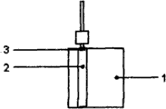
Accompanying drawing 1 is on the Metal Flake main body of the utility model negative plate, laterally places the main pseudosection of length strip metal net inequality;
When accompanying drawing 2 is the utility model negative plate adjusting centre-to-centre spacing, laterally place the main pseudosection of length strip metal net inequality on the Metal Flake main body;
When accompanying drawing 3 is the automated production of the utility model negative plate, laterally place the main pseudosection of the identical strip metal net of length on the Metal Flake main body;
When accompanying drawing 4 is the utility model negative plate automated production adjusting centre-to-centre spacing, laterally place the main pseudosection of the identical strip metal net of length on the Metal Flake main body;
When accompanying drawing 5 is the production of the utility model negative plate lamination, vertically place the main pseudosection of the identical strip metal net of length on the Metal Flake main body;
Accompanying drawing 6 is on the Metal Flake main body of the utility model negative plate, laterally places the main pseudosection of length sticky foil inequality;
When accompanying drawing 7 is the utility model negative plate adjusting centre-to-centre spacing, laterally place the main pseudosection of length sticky foil inequality on the Metal Flake main body;
When accompanying drawing 8 is the automated production of the utility model negative plate, laterally place the main pseudosection of the identical sticky foil of length on the Metal Flake main body;
When accompanying drawing 9 is the utility model negative plate automated production adjusting centre-to-centre spacing, laterally place the main pseudosection of the identical sticky foil of length on the Metal Flake main body;
When accompanying drawing 10 is the production of the utility model negative plate lamination, vertically place the main pseudosection of the identical sticky foil of length on the Metal Flake main body;
Accompanying drawing 11 is discharge performance curve charts of prior art;
Accompanying drawing 12 is discharge performance curve charts of the present utility model.
Embodiment:
It is compressed together with it at first to go up placement strip metal (2) in flake main body (1), negative lug (3) and its pressing is inlayed make an integral body again.Flake main body (1) is metallic lithium foil or lithium-aluminium alloy paper tinsel.Strip metal (2) is wire netting or metal forming; Its material is any of copper mesh, Copper Foil, aluminium net, aluminium foil, nickel screen, nickel foil, steel mesh, steel foil.Negative lug (3) is an attached PUR on the pure nickel nickel bar.
What exemplify below is the production instance of different materials position:
As Fig. 1 and shown in Figure 6, on flake main body (1), laterally place strip metal (2), strip metal (2) is inequality with flake main body (1) length, be embedded on the flake main body (1) of partial-length through process for pressing, again negative lug (3) be placed on the edge and the composition negative plate is inlayed in its pressing.
When regulating centre-to-centre spacing, as Fig. 2 and shown in Figure 7, on flake main body (1), laterally place strip metal (2), strip metal (2) is inequality with flake main body (1) length, be embedded on the flake main body (1) of partial-length through process for pressing, again negative lug (3) be placed on isolated edge and inlay the composition negative plate with its pressing nearby.
When automated production, as Fig. 3 and shown in Figure 8, on flake main body (1), laterally place strip metal (2), strip metal (2) is identical with flake main body (1) length, be embedded on the flake main body (1) of full wafer length through process for pressing, again negative lug (3) be placed on the edge and the composition negative plate is inlayed in its pressing.
When centre-to-centre spacing is regulated in automated production, as Fig. 4 and shown in Figure 9, on flake main body (1), laterally place strip metal (2), strip flake main body (1) length is identical, be embedded on the flake main body (1) of full wafer length through process for pressing, again negative lug (3) be placed on isolated edge and inlay the composition negative plate with its pressing nearby.
When lamination is produced, as Fig. 5 and shown in Figure 10, on flake main body (1), vertically place strip metal (2), strip metal (1) is identical with flake main body (2) length, be embedded on the flake main body (1) of full wafer length through process for pressing, again the composition negative plate inlayed in negative lug (3) and its pressing.
Claims (4)
1. lithium metal primary cell negative plate, it comprises flake main body, it is characterized in that: strip metal is set in flake main body; Negative lug is set connects flake main body and strip metal.
2. lithium metal primary cell negative plate as claimed in claim 1 is characterized in that: described flake main body is metallic lithium foil or lithium-aluminium alloy paper tinsel.
3. lithium metal primary cell negative plate as claimed in claim 1 is characterized in that: described strip metal is wire netting or metal forming.
4. lithium metal primary cell negative plate as claimed in claim 1 is characterized in that: described negative lug is an attached PUR on the pure nickel nickel bar.
Priority Applications (1)
| Application Number | Priority Date | Filing Date | Title |
|---|---|---|---|
| CN2011200327782U CN202019016U (en) | 2011-01-30 | 2011-01-30 | Negative sheet of metal lithium primary battery |
Applications Claiming Priority (1)
| Application Number | Priority Date | Filing Date | Title |
|---|---|---|---|
| CN2011200327782U CN202019016U (en) | 2011-01-30 | 2011-01-30 | Negative sheet of metal lithium primary battery |
Publications (1)
| Publication Number | Publication Date |
|---|---|
| CN202019016U true CN202019016U (en) | 2011-10-26 |
Family
ID=44812684
Family Applications (1)
| Application Number | Title | Priority Date | Filing Date |
|---|---|---|---|
| CN2011200327782U Expired - Lifetime CN202019016U (en) | 2011-01-30 | 2011-01-30 | Negative sheet of metal lithium primary battery |
Country Status (1)
| Country | Link |
|---|---|
| CN (1) | CN202019016U (en) |
Cited By (3)
| Publication number | Priority date | Publication date | Assignee | Title |
|---|---|---|---|---|
| CN102623670A (en) * | 2011-01-30 | 2012-08-01 | 深圳市艾博尔新能源有限公司 | Lithium metal primary cell negative flake |
| CN105304856A (en) * | 2014-08-01 | 2016-02-03 | 中国电子科技集团公司第十八研究所 | Preparation method of negative plate of primary lithium battery |
| CN105655534A (en) * | 2015-12-30 | 2016-06-08 | 中国电子科技集团公司第十八研究所 | Coiled primary lithium battery cathode structure |
-
2011
- 2011-01-30 CN CN2011200327782U patent/CN202019016U/en not_active Expired - Lifetime
Cited By (4)
| Publication number | Priority date | Publication date | Assignee | Title |
|---|---|---|---|---|
| CN102623670A (en) * | 2011-01-30 | 2012-08-01 | 深圳市艾博尔新能源有限公司 | Lithium metal primary cell negative flake |
| CN105304856A (en) * | 2014-08-01 | 2016-02-03 | 中国电子科技集团公司第十八研究所 | Preparation method of negative plate of primary lithium battery |
| CN105655534A (en) * | 2015-12-30 | 2016-06-08 | 中国电子科技集团公司第十八研究所 | Coiled primary lithium battery cathode structure |
| CN105655534B (en) * | 2015-12-30 | 2018-09-11 | 中国电子科技集团公司第十八研究所 | A kind of coiling lithium one-shot battery negative pole structure |
Similar Documents
| Publication | Publication Date | Title |
|---|---|---|
| CN205666257U (en) | Utmost point post riveting flexible connecting piece's lithium ion battery cover plate | |
| CN202019016U (en) | Negative sheet of metal lithium primary battery | |
| CN105304856A (en) | Preparation method of negative plate of primary lithium battery | |
| CN102623670A (en) | Lithium metal primary cell negative flake | |
| CN202004074U (en) | Connection structure of conductive terminals of lithium ion battery | |
| CN201918464U (en) | High rate cylindrical lithium-ion battery | |
| CN203225300U (en) | Pole ear connecting device for dynamical type soft roll lithium battery module | |
| CN202601763U (en) | High-multiplying-power lithium ion battery of multi-tab structure | |
| CN202996964U (en) | Electric vehicle accumulator plate | |
| CN202231110U (en) | Lithium ion secondary battery | |
| CN103746120B (en) | A kind of battery grid | |
| CN104134803A (en) | Super-pore stretching-mesh lead-acid battery grid | |
| CN203895570U (en) | Valve-regulated sealed lead-acid battery | |
| CN203288687U (en) | High-capacity battery, and electrode plate and conductive substrate thereof | |
| CN203134918U (en) | High-power nickel-metal hydride battery | |
| CN2924795Y (en) | Lithium ion secondary cell for preventing cell micro short circuit | |
| CN202332891U (en) | Solar battery junction box and lead connecting terminal structure therein | |
| CN202231109U (en) | Novel cylinder lithium ion battery | |
| CN201413841Y (en) | Hydrogen storage alloy electrode for high current nickel-hydrogen battery | |
| CN201340882Y (en) | High-power laminated lithium ion battery | |
| CN202905725U (en) | Hybrid back electrode cell piece | |
| CN206432271U (en) | Solar energy is without main gate line crystal-silicon battery slice | |
| CN202111175U (en) | A composite metal lithium ribbon | |
| CN204596876U (en) | A kind of grid of winding type lead-acid battery | |
| CN202977577U (en) | Secondary battery capable of improving high-rate discharge property of secondary battery |
Legal Events
| Date | Code | Title | Description |
|---|---|---|---|
| C14 | Grant of patent or utility model | ||
| GR01 | Patent grant | ||
| CX01 | Expiry of patent term | ||
| CX01 | Expiry of patent term |
Granted publication date: 20111026 |
|
| DD01 | Delivery of document by public notice | ||
| DD01 | Delivery of document by public notice |
Addressee: Patent director of Shenzhen Aibo new energy Co.,Ltd. Document name: Notice of termination of patent right |