CN202128137U - Improved Structure of Chair Back Lifting Device - Google Patents
Improved Structure of Chair Back Lifting Device Download PDFInfo
- Publication number
- CN202128137U CN202128137U CN201120176045U CN201120176045U CN202128137U CN 202128137 U CN202128137 U CN 202128137U CN 201120176045 U CN201120176045 U CN 201120176045U CN 201120176045 U CN201120176045 U CN 201120176045U CN 202128137 U CN202128137 U CN 202128137U
- Authority
- CN
- China
- Prior art keywords
- frame
- chair back
- chair
- slide block
- rail frame
- Prior art date
- Legal status (The legal status is an assumption and is not a legal conclusion. Google has not performed a legal analysis and makes no representation as to the accuracy of the status listed.)
- Expired - Fee Related
Links
- 229910000831 Steel Inorganic materials 0.000 claims abstract description 18
- 239000010959 steel Substances 0.000 claims abstract description 18
- 238000006073 displacement reaction Methods 0.000 claims abstract description 16
- 210000002268 wool Anatomy 0.000 claims description 6
- 230000015572 biosynthetic process Effects 0.000 description 5
- 238000005755 formation reaction Methods 0.000 description 5
- 238000010521 absorption reaction Methods 0.000 description 4
- 210000001364 upper extremity Anatomy 0.000 description 3
- 230000009286 beneficial effect Effects 0.000 description 1
Images




Landscapes
- Chairs For Special Purposes, Such As Reclining Chairs (AREA)
Abstract
An improved structure of a chair back lifting device belongs to the class of articles for daily use and mainly comprises a slide rail frame and a fixing frame which can move up and down along the slide rail frame. The slide rail frame is provided with positioning holes at two sides at intervals, the fixing frame is provided with a slide block, the slide block is provided with an elastic steel ball, and the slide block is provided with a fixing frame. The slide rail frame is arranged on the chair frame of a sofa or other seats, and the fixing frame is arranged at the back of the seat, so that the chair back moves up and down along the chair frame by the up-and-down displacement of the fixing frame along the slide rail frame and the embedding of the steel balls arranged on the slide block to the positioning holes at different positions, and the height of the chair back of the seats such as the sofa and the like is adjusted.
Description
Technical field
The utility model relates to daily class; Structure-improved for relevant a kind of chair back lowering or hoisting gear; Especially refer to a kind ofly, make the chair back, and then make the chair back of seat such as sofa constitute the structure-improved of the chair back lowering or hoisting gear of high and low adjustment along the upper and lower displacement of chair frame by simple upper and lower pulling to the chair back.
Background technology
The chair back of the chair tool of general as sofa or other form is made as fixedly usually, therefore, is just sitting or when reclining, because the height of the chair back can't be adjusted, makes the seat person for sleeping in of different heights feel under the weather when straight.Though some product is considered height adjustable structure; The dealer of these products is provided with structures such as flexible, clamping between the two articles that is connected, the chair back can be gone up and down along seats such as sofas; Its existing lifting structure is comparatively complicated; Not only inconvenient in the operation, and cost is higher lacks competitiveness, and very undesirable.
The utility model content
The main purpose of the utility model is to provide a kind of structure-improved of chair back lowering or hoisting gear; Make the chair back of seats such as sofa, be able to, make chair back rack along the upper and lower displacement of chair frame by simply pulling; And then constitute the high and low adjustment of the chair back, and its operation is simple and easy, convenience.
The structure-improved of aforesaid chair back lowering or hoisting gear comprises sliding rail frame and can be along the fixed mount of the upper and lower displacement of this sliding rail frame.Wherein, this sliding rail frame is respectively equipped with spaced locating hole in both sides, and this fixed mount is provided with a slide block, is provided with the flexible steel ball of tool in slide block, and is provided with fixed mount in this slide block.Sliding rail frame is installed in the chair frame of the seat of sofa or other form; And after fixed mount is installed in the chair back; Be able to by the upper and lower displacement of fixed mount along sliding rail frame; And by the set steel ball of slide block to the setting of diverse location locating hole, the chair back is moved along the chair frame is upper and lower, and then makes the chair back of seats such as sofa constitute high and low adjustment.
The structure-improved of aforesaid chair back lowering or hoisting gear, wherein this is located at the slide block of fixed mount, in the surface that fits in sliding rail frame, is provided with vertical zigzag striped, and the friction during with the minimizing displacement makes high and low adjustment more smooth and easy.
The utility model specifically comprises:
Sliding rail frame, its upper and lower edge are provided with the fixing hole that supplies to be fixed in the chair frame respectively, and both sides then are respectively equipped with spaced locating hole;
Fixed mount is installed in the chair back, and it is provided with the slide block that without exception is convex; Be provided with the sliding rail frame locating hole in the side of slide block and be corresponding trepanning; In trepanning inserting spring and steel ball, slide block set is placed sliding rail frame, make steel ball be able to be embedded at respectively locating hole; The surface of slide block is provided with slotted eye, inserts magnet and wool felt in this slotted eye; An and fixed mount; Be provided with the backstay of horizontal projection in this fixed mount; This fixed mount and magnet absorption are fixed on the slide block, by the upper and lower displacement of fixed mount along sliding rail frame, and by the set steel ball of slide block setting the diverse location locating hole; The chair back is moved along the chair frame is upper and lower, and then make the high and low adjustment of chair back formation of seats such as sofa.
Wherein, the upper limb of the last fixing hole of this sliding rail frame is provided with one and constitutes spacing stopper section when making slide block make progress slippage, constitutes spacingly when making slide block make progress slippage by this stopper section, on preventing excessively, moves the disengaging sliding rail frame;
Wherein, this is located at the slide block of fixed mount, is provided with the zigzag striped of vertical friction when reducing displacement in the back side;
Wherein, the slotted eye that this is located at slide block is made as front end and then holds than major diameter than minor diameter, is beneficial to and inserts magnet and wool felt.
The advantage of the utility model is: be located at the slide block of fixed mount, in the surface that fits in sliding rail frame, be provided with vertical zigzag striped; Friction during with the minimizing displacement makes high and low adjustment more smooth and easy, by the upper and lower displacement of fixed mount along sliding rail frame; And by the set steel ball of slide block setting to the diverse location locating hole; The chair back is moved along the chair frame is upper and lower, and then make the high and low adjustment of chair back formation of seats such as sofa, and its operation is simple and easy, convenience.
Description of drawings
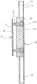
Fig. 1 is the stereogram of the utility model.
Fig. 2 is the three-dimensional exploded view of the utility model.
Fig. 3 is the cutaway view of the utility model.
Fig. 4 is another cutaway view of the utility model.
Fig. 5 is the assembling of the utility model and uses and implement illustration.
Fig. 6 uses and uses the enforcement illustration for the utility model.
The specific embodiment
Shown in accompanying drawing 1 and accompanying drawing 2, and conjunction with figs. 3, be stereogram, three-dimensional exploded view and the cutaway view of the utility model.As shown in the figure, the utility model comprises sliding rail frame 10 and can be along the fixed mount 20 of these sliding rail frame 10 upper and lower displacements.Wherein, in present embodiment, this sliding rail frame 10 generally is the ㄇ shape, and the upper and lower edge in the surface is provided with fixing hole 11,12 respectively, and is provided with a stopper section 13 in the upper limb of fixing hole 11, and sliding rail frame 10 dual-sides then are respectively equipped with spaced locating hole 14;
This fixed mount 20 is provided with the slide block 2 that without exception is convex, is provided with sliding rail frame 10 locating holes 14 in the side of slide block 2 to be corresponding trepanning 21; In trepanning 21 inserting springs 22 and steel ball 23 (left and right each steel ball 23), make steel ball 23 constitute suitable elasticity, slide block 2 is placed on sliding rail frame 10; Make steel ball 23 be able to be embedded at respectively locating hole 14; The back side that slide block 2 and sliding rail frame 10 are fitted then is provided with vertical zigzag striped 24, the friction during with the minimizing displacement;
The surface of slide block 2 is provided with front end and then holds larger-diameter slotted eye 25 than minor diameter, inserts magnet 26 and wool felt 27 in this slotted eye 25; And a lamellar body 3, be provided with the backstay 31 of horizontal projection in this fixed mount 3, and the fixing hole 32 of plural number, make this lamellar body 3 be able to be fixed on the slide block 2 by the absorption of backstay 31 with magnet 26;
By the combination of aforementioned components, constitute the structure-improved of chair back lowering or hoisting gear.Sliding rail frame 10 is installed in the chair frame of the seat of sofa or other form by fixing hole 11,12; And after fixed mount 20 is installed in the chair back by the fixing hole 32 of lamellar body 3; Make wherein backstay 31 be embedded at the set slotted eye 25 of slide block 2 of sliding rail frame 10; Magnet 26 absorption location with in the slotted eye 25 are able to by the upper and lower displacement of fixed mount 20 along sliding rail frame 10, and setting by slide block 2 set 23 pairs of diverse location locating holes 14 of steel ball; The chair back is moved along the chair frame is upper and lower, and then make the high and low adjustment person of chair back formation of seats such as sofa.And slide block 2 fits in the set vertical zigzag striped 24 in sliding rail frame 10 surfaces, the friction during with the minimizing displacement, and because slotted eye 25 has been inserted wool felt 27, it is more smooth and easy that high and low adjustment is able to.
Shown in accompanying drawing 4, be another cutaway view of the utility model.As shown in the figure, the slide block 2 of the fixed mount 20 of the utility model is embedded at sliding rail frame 10; After setting, make setting of slide block 2 set 23 pairs of diverse location locating holes 14 of steel ball; Upper and lower when mobile along sliding rail frame 10 when slide block 2, these steel balls 23 can be withdrawed from by locating hole 14 earlier, again after sliding rail frame 10 side slippages; Be embedded at the locating hole 14 of other position, thereby constitute the adjustment of high and low position and the adjusted location of the chair back.Because the upper limb of the fixing hole 1 of this sliding rail frame 10 is provided with a stopper section 13, spacing when making slide block 2 make progress slippage by these stopper section 13 formations, break away from sliding rail frame 10 to move on preventing excessively;
Shown in accompanying drawing 5, be the assembled embodiment figure of the utility model.Would like to ask conjunction with figs. 2; As shown in the figure; The utility model is in when assembling, and sliding rail frame 10 is installed in the chair frame 41 of the seat 4 of sofa or other form, and after fixed mount 20 is installed in the chair back 42; Make the backstay 31 of lamellar body 3 wherein be embedded at the set slotted eye 25 of slide block 2 of sliding rail frame 10, with the magnet 26 absorption location in the slotted eye 25.
Shown in accompanying drawing 6, for illustration is implemented in the use of the utility model.Would like to ask conjunction with figs. 2; The utility model is when using; With the chair back 42 direct upper and lower pulling, by the upper and lower displacement of fixed mount 20 along sliding rail frame 10, and setting by slide block 2 set 23 pairs of diverse location locating holes 14 of steel ball; The chair back 42 is able to along chair frame 41 upper and lower moving, and then makes the adjustment of the high and low position of the chair back 42 formations of seats 4 such as sofa.
Claims (4)
Priority Applications (1)
| Application Number | Priority Date | Filing Date | Title |
|---|---|---|---|
| CN201120176045U CN202128137U (en) | 2011-05-30 | 2011-05-30 | Improved Structure of Chair Back Lifting Device |
Applications Claiming Priority (1)
| Application Number | Priority Date | Filing Date | Title |
|---|---|---|---|
| CN201120176045U CN202128137U (en) | 2011-05-30 | 2011-05-30 | Improved Structure of Chair Back Lifting Device |
Publications (1)
| Publication Number | Publication Date |
|---|---|
| CN202128137U true CN202128137U (en) | 2012-02-01 |
Family
ID=45516925
Family Applications (1)
| Application Number | Title | Priority Date | Filing Date |
|---|---|---|---|
| CN201120176045U Expired - Fee Related CN202128137U (en) | 2011-05-30 | 2011-05-30 | Improved Structure of Chair Back Lifting Device |
Country Status (1)
| Country | Link |
|---|---|
| CN (1) | CN202128137U (en) |
Cited By (10)
| Publication number | Priority date | Publication date | Assignee | Title |
|---|---|---|---|---|
| CN108135363A (en) * | 2015-09-07 | 2018-06-08 | 宜家供应有限公司 | Sofa bed and sofa bed sliding system for such a sofa bed |
| CN108136435A (en) * | 2015-09-07 | 2018-06-08 | 宜家供应有限公司 | Low friction sliding component |
| CN108236244A (en) * | 2016-12-27 | 2018-07-03 | 中山利德丰造船有限公司 | chair with adjustable back |
| CN108236242A (en) * | 2016-12-27 | 2018-07-03 | 中山利德丰造船有限公司 | Chair (Ref. TM. chair) |
| CN108236245A (en) * | 2016-12-27 | 2018-07-03 | 中山利德丰造船有限公司 | The adjustable chair of backrest height |
| CN109124140A (en) * | 2018-09-27 | 2019-01-04 | 浙江粤强家具科技有限公司 | Backrest of rotary chair elevating mechanism |
| US11187020B2 (en) | 2015-09-07 | 2021-11-30 | Ikea Supply Ag | Sliding screen sliding system |
| US11229286B2 (en) | 2015-09-07 | 2022-01-25 | Ikea Supply Ag | Drawer, and a drawer sliding system for such drawer |
| US11332685B2 (en) | 2017-03-03 | 2022-05-17 | Ikea Supply Ag | Furniture lubricant |
| US11933358B2 (en) | 2017-03-03 | 2024-03-19 | Ikea Supply Ag | Furniture rotary system having reduced friction, and a piece of furniture comprising such system |
-
2011
- 2011-05-30 CN CN201120176045U patent/CN202128137U/en not_active Expired - Fee Related
Cited By (14)
| Publication number | Priority date | Publication date | Assignee | Title |
|---|---|---|---|---|
| US11578754B2 (en) | 2015-09-07 | 2023-02-14 | Ikea Supply Ag | Low friction slide member |
| US12428889B2 (en) | 2015-09-07 | 2025-09-30 | Inter Ikea Systems B.V. | Sliding screen sliding system |
| US11229286B2 (en) | 2015-09-07 | 2022-01-25 | Ikea Supply Ag | Drawer, and a drawer sliding system for such drawer |
| US12098747B2 (en) | 2015-09-07 | 2024-09-24 | Ikea Supply Ag | Low friction slide member |
| US11187020B2 (en) | 2015-09-07 | 2021-11-30 | Ikea Supply Ag | Sliding screen sliding system |
| CN108135363A (en) * | 2015-09-07 | 2018-06-08 | 宜家供应有限公司 | Sofa bed and sofa bed sliding system for such a sofa bed |
| CN108136435A (en) * | 2015-09-07 | 2018-06-08 | 宜家供应有限公司 | Low friction sliding component |
| CN108236245A (en) * | 2016-12-27 | 2018-07-03 | 中山利德丰造船有限公司 | The adjustable chair of backrest height |
| CN108236242A (en) * | 2016-12-27 | 2018-07-03 | 中山利德丰造船有限公司 | Chair (Ref. TM. chair) |
| CN108236244A (en) * | 2016-12-27 | 2018-07-03 | 中山利德丰造船有限公司 | chair with adjustable back |
| US11332685B2 (en) | 2017-03-03 | 2022-05-17 | Ikea Supply Ag | Furniture lubricant |
| US11933358B2 (en) | 2017-03-03 | 2024-03-19 | Ikea Supply Ag | Furniture rotary system having reduced friction, and a piece of furniture comprising such system |
| US12546363B2 (en) | 2017-03-03 | 2026-02-10 | Inter Ikea Systems B.V. | Furniture rotary system having reduced friction, and a piece of furniture comprising such system |
| CN109124140A (en) * | 2018-09-27 | 2019-01-04 | 浙江粤强家具科技有限公司 | Backrest of rotary chair elevating mechanism |
Similar Documents
| Publication | Publication Date | Title |
|---|---|---|
| CN202128137U (en) | Improved Structure of Chair Back Lifting Device | |
| CN202858483U (en) | Sofa with adjustable three sides | |
| CN103462402B (en) | A kind of chair | |
| CN201403860Y (en) | Adjusting structure of chair waist support | |
| CN204708366U (en) | A kind of office chair back with elevation and subsidence regulating device | |
| CN210018577U (en) | Multipurpose office chair for office | |
| CN203341343U (en) | Seat with backrest capable of being adjusted forward and backward | |
| CN201814173U (en) | Headrest | |
| CN203378769U (en) | Chair with sliding device | |
| CN203388557U (en) | Double-backrest chair with backrest heights convenient to adjust | |
| CN203619138U (en) | Bed capable of being comfortably lay | |
| CN102951044A (en) | Angle-adjustable safety chair for children | |
| CN202009891U (en) | Novel retractable bed | |
| CN201958283U (en) | Adjustable armrest support structure | |
| CN201480671U (en) | Height adjusting structure for chair armrest | |
| CN203886096U (en) | Waist building machine | |
| TWM411855U (en) | Improved structure of lifting/lowering device for chair back | |
| CN202775308U (en) | Height increasing chair | |
| CN104665337A (en) | Bed provided with inclined headboard | |
| CN202698625U (en) | Pillow | |
| CN202408021U (en) | Connecting mechanism of handrails and chair body of baby chair | |
| CN203328307U (en) | Swivel chair with multifunctional adjusting device | |
| CN205197493U (en) | Chair convenient to write | |
| CN203524228U (en) | Waist pillow and chair | |
| CN203073781U (en) | Chair backrest framework capable of moving back and forth |
Legal Events
| Date | Code | Title | Description |
|---|---|---|---|
| C14 | Grant of patent or utility model | ||
| GR01 | Patent grant | ||
| C17 | Cessation of patent right | ||
| CF01 | Termination of patent right due to non-payment of annual fee |
Granted publication date: 20120201 Termination date: 20140530 |