CN202128671U - Phalanx knuckle rehabilitating mechanism of pedal type tread rehabilitation trainer - Google Patents
Phalanx knuckle rehabilitating mechanism of pedal type tread rehabilitation trainer Download PDFInfo
- Publication number
- CN202128671U CN202128671U CN201120201701U CN201120201701U CN202128671U CN 202128671 U CN202128671 U CN 202128671U CN 201120201701 U CN201120201701 U CN 201120201701U CN 201120201701 U CN201120201701 U CN 201120201701U CN 202128671 U CN202128671 U CN 202128671U
- Authority
- CN
- China
- Prior art keywords
- rehabilitation
- connecting rod
- joint
- rehabilitation mechanism
- phalanx
- Prior art date
- Legal status (The legal status is an assumption and is not a legal conclusion. Google has not performed a legal analysis and makes no representation as to the accuracy of the status listed.)
- Expired - Lifetime
Links
- 230000007246 mechanism Effects 0.000 title claims abstract description 45
- 230000005021 gait Effects 0.000 claims abstract description 31
- 238000005452 bending Methods 0.000 claims abstract description 13
- 230000001681 protective effect Effects 0.000 claims description 5
- 125000006850 spacer group Chemical group 0.000 claims 3
- 210000001872 metatarsal bone Anatomy 0.000 abstract description 8
- 206010061225 Limb injury Diseases 0.000 abstract description 4
- 210000003141 lower extremity Anatomy 0.000 abstract description 4
- 210000003423 ankle Anatomy 0.000 abstract description 3
- 210000000689 upper leg Anatomy 0.000 abstract description 3
- 208000024172 Cardiovascular disease Diseases 0.000 abstract description 2
- 206010033799 Paralysis Diseases 0.000 abstract description 2
- 208000026106 cerebrovascular disease Diseases 0.000 abstract description 2
- 230000002526 effect on cardiovascular system Effects 0.000 abstract description 2
- 210000002683 foot Anatomy 0.000 description 29
- 210000000544 articulatio talocruralis Anatomy 0.000 description 3
- 210000003414 extremity Anatomy 0.000 description 3
- 230000005484 gravity Effects 0.000 description 3
- 210000001503 joint Anatomy 0.000 description 3
- 244000309466 calf Species 0.000 description 2
- 238000010586 diagram Methods 0.000 description 2
- 238000000034 method Methods 0.000 description 2
- 230000007659 motor function Effects 0.000 description 2
- 210000003205 muscle Anatomy 0.000 description 2
- 206010003694 Atrophy Diseases 0.000 description 1
- 241000282412 Homo Species 0.000 description 1
- 206010023201 Joint contracture Diseases 0.000 description 1
- 206010023230 Joint stiffness Diseases 0.000 description 1
- 244000208734 Pisonia aculeata Species 0.000 description 1
- 230000009471 action Effects 0.000 description 1
- 230000037444 atrophy Effects 0.000 description 1
- 206010008129 cerebral palsy Diseases 0.000 description 1
- 230000008859 change Effects 0.000 description 1
- 230000000694 effects Effects 0.000 description 1
- 210000004744 fore-foot Anatomy 0.000 description 1
- 230000006870 function Effects 0.000 description 1
- 230000008407 joint function Effects 0.000 description 1
- 230000004220 muscle function Effects 0.000 description 1
- 238000011084 recovery Methods 0.000 description 1
- 238000004088 simulation Methods 0.000 description 1
- 238000002560 therapeutic procedure Methods 0.000 description 1
- 210000003371 toe Anatomy 0.000 description 1
- 238000003466 welding Methods 0.000 description 1
Images


Landscapes
- Rehabilitation Tools (AREA)
Abstract
本实用新型的目的在于提供踏板式步态康复训练器趾骨关节的康复机构,包括弯杆、立式摇杆支柱、趾骨关节康复机构、连杆、底板、曲柄、力矩电机,立式摇杆支柱固定在底板的前端,力矩电机固定在底板的后端,弯杆的上端与立式摇杆支柱相连,弯杆的下端连接连杆,连杆与曲柄相连,曲柄连接力矩电机,趾骨关节康复机构与连杆相连,所述的弯杆、连杆、趾骨关节康复机构、曲柄均有两个且对称位于立式摇杆支柱两侧。本实用新型结构简单,使用方便,具有大腿、小腿、脚踝和跖骨四个关节驱动能力。适用于心脑血管疾病致瘫和因意外事故等造成的下肢损伤患者做康复训练,也可适用于步态畸形的患者。运动幅度、速度可根据患者实际情况改变,应用范围广。
The purpose of this utility model is to provide the rehabilitation mechanism of the phalanx joint of the pedal type gait rehabilitation trainer, including a bent bar, a vertical rocker pillar, a phalanx joint rehabilitation mechanism, a connecting rod, a base plate, a crank, a torque motor, and a vertical rocker pillar Fixed on the front end of the base plate, the torque motor is fixed on the rear end of the base plate, the upper end of the bending rod is connected with the vertical rocker pillar, the lower end of the bending rod is connected with the connecting rod, the connecting rod is connected with the crank, the crank is connected with the torque motor, and the phalange joint rehabilitation mechanism Linked to each other with the connecting rod, there are two bent rods, connecting rods, phalangeal joint rehabilitation mechanism, and cranks, which are symmetrically located on both sides of the vertical rocker pillar. The utility model has the advantages of simple structure and convenient use, and has the driving ability of four joints of the thigh, the lower leg, the ankle and the metatarsal bone. It is suitable for rehabilitation training for patients with paralysis caused by cardiovascular and cerebrovascular diseases and lower limb injuries caused by accidents, and also for patients with gait deformity. The range and speed of movement can be changed according to the actual situation of the patient, and the application range is wide.
Description
技术领域 technical field
本实用新型涉及的是一种患者康复训练用器械。The utility model relates to a device for patient rehabilitation training.
背景技术 Background technique
医学理论和实践已经证明,脑瘫后遗症或意外事故造成的肢体损伤患者必须进行肢体训练,以便恢复肢体功能,防止肌肉“废用性”萎缩和关节僵硬。近年来,康复训练器对患者进行科学而又有效的康复训练的方式表现出了越来越多的优势。及早开展康复训练不仅能够维持关节活动度、防止关节挛缩,而且能够明显提高患者运动功能的最终恢复程度。其中被动运动训练是肢体运动功能康复训练疗法中的一种基本方法。Medical theory and practice have proved that patients with limb injuries caused by cerebral palsy sequelae or accidents must perform limb training in order to restore limb function and prevent muscle "disuse" atrophy and joint stiffness. In recent years, rehabilitation trainers have shown more and more advantages in scientific and effective rehabilitation training for patients. Early rehabilitation training can not only maintain the joint range of motion and prevent joint contracture, but also significantly improve the final recovery of the patient's motor function. Among them, passive movement training is a basic method in the rehabilitation training therapy of limb motor function.
现有的有关步态康复机器人一般通过大腿、小腿摆动和脚踝的转动实现对人类步态的模拟,忽略了人类脚部跖骨关节在步态中的作用。一组完美的步态,必须允许患者能够轻松地、长时间进行步行运动。在约占整个步态周期的60-65%的下肢接触地面和承受重力的时间即支撑时相里,跖骨关节起到了非常重要的作用。在支撑相时间里,人体重心从脚跟移动到脚趾,足底力表现为为双突峰曲线。在步态康复机器人中加入跖骨关节,一方面使得步态曲线更接近人类真实的步态曲线,另一方面可以使足底力符合双突峰特征。The existing gait rehabilitation robots generally realize the simulation of human gait through the swing of thigh and calf and the rotation of ankle, ignoring the role of human foot metatarsal joints in gait. A perfect set of gaits must allow the patient to walk easily and for extended periods of time. The metatarsal joint plays a very important role in the stance phase, the time when the lower extremity is in contact with the ground and bears gravity, which accounts for about 60-65% of the entire gait cycle. During the stance phase, the center of gravity of the human body moves from the heel to the toes, and the plantar force is manifested as a double peak curve. Adding metatarsal joints to the gait rehabilitation robot can make the gait curve closer to the real gait curve of humans on the one hand, and can make the plantar force conform to the characteristics of double peaks on the other hand.
发明内容 Contents of the invention
本实用新型的目的在于提供用于下肢损伤患者的肌肉和关节功能训练的踏板式步态康复训练器趾骨关节的康复机构。The purpose of the utility model is to provide a pedal type gait rehabilitation trainer for the rehabilitation mechanism of the phalanx joint for the muscle and joint function training of patients with lower limb injuries.
本实用新型的目的是这样实现的:The purpose of this utility model is achieved in that:
本实用新型踏板式步态康复训练器趾骨关节的康复机构,其特征是:包括弯杆、立式摇杆支柱、趾骨关节康复机构、连杆、底板、曲柄、力矩电机,立式摇杆支柱固定在底板的前端,力矩电机固定在底板的后端,弯杆的上端与立式摇杆支柱相连,弯杆的下端连接连杆,连杆与曲柄相连,曲柄连接力矩电机,趾骨关节康复机构与连杆相连,所述的弯杆、连杆、趾骨关节康复机构、曲柄均有两个且对称位于立式摇杆支柱两侧。The rehabilitation mechanism of the phalanx joint of the pedal type gait rehabilitation trainer of the utility model is characterized in that it comprises a curved rod, a vertical rocker pillar, a phalanx joint rehabilitation mechanism, a connecting rod, a bottom plate, a crank, a torque motor, and a vertical rocker pillar Fixed on the front end of the base plate, the torque motor is fixed on the rear end of the base plate, the upper end of the bending rod is connected with the vertical rocker pillar, the lower end of the bending rod is connected with the connecting rod, the connecting rod is connected with the crank, the crank is connected with the torque motor, and the phalange joint rehabilitation mechanism Linked to each other with the connecting rod, there are two bent rods, connecting rods, phalangeal joint rehabilitation mechanism, and cranks, which are symmetrically located on both sides of the vertical rocker pillar.
本实用新型还可以包括:The utility model can also include:
1、所述的趾骨关节康复机构包括脚前板、长弹簧轴、滑轮、合页、短弹簧轴、后脚板、直线轴承连接块、滑块、滑轨、滑轨支撑架,前脚板和后脚板通过合页相连,前脚板底部安装长弹簧轴,滑轮安装在长弹簧轴的一端,后脚板底部安装短弹簧轴,长弹簧轴和短弹簧轴通过弹簧相连,后脚板通过直线轴承连接块连接滑块,滑块安装在滑轨上,滑轨固定在滑轨支撑架上。1. The phalanx joint rehabilitation mechanism includes a front plate, a long spring shaft, a pulley, a hinge, a short spring shaft, a rear foot plate, a linear bearing connection block, a slider, a slide rail, a slide rail support frame, a front foot plate and a rear foot plate. The foot plates are connected by hinges, the bottom of the front foot plate is installed with a long spring shaft, the pulley is installed at one end of the long spring shaft, the bottom of the rear foot plate is equipped with a short spring shaft, the long spring shaft and the short spring shaft are connected by a spring, and the rear foot plate is connected by a linear bearing connection block The slide block is installed on the slide rail, and the slide rail is fixed on the slide rail supporting frame.
2、还包括限位槽,限位槽的底部固定在底板上,限位槽的上部与趾骨关节康复机构的滑轮相配合。2. It also includes a limiting groove, the bottom of which is fixed on the base plate, and the upper part of the limiting groove cooperates with the pulley of the phalanx joint rehabilitation mechanism.
3、所述的底板为平面框架式结构。3. The bottom plate is a plane frame structure.
4、所述的前脚板和后脚板周边固定防护框。4. A protective frame is fixed around the front foot plate and the rear foot plate.
5、所述的后脚板的底部安装支承轴,趾骨关节康复机构通过支承轴与连杆相连。5. A supporting shaft is installed at the bottom of the rear foot plate, and the phalanx joint rehabilitation mechanism is connected with the connecting rod through the supporting shaft.
本实用新型的优势在于:本实用新型结构简单,使用方便,具有大腿、小腿、脚踝和跖骨四个关节驱动能力。适用于心脑血管疾病致瘫和因意外事故等造成的下肢损伤患者做康复训练,也可适用于步态畸形的患者。运动幅度、速度可根据患者实际情况改变,应用范围广。The utility model has the advantages that: the utility model is simple in structure, easy to use, and has four joint driving capabilities of the thigh, the calf, the ankle and the metatarsal bone. It is suitable for rehabilitation training for patients with paralysis caused by cardiovascular and cerebrovascular diseases and lower limb injuries caused by accidents, and also for patients with gait deformity. The range and speed of movement can be changed according to the actual situation of the patient, and the application range is wide.
附图说明 Description of drawings
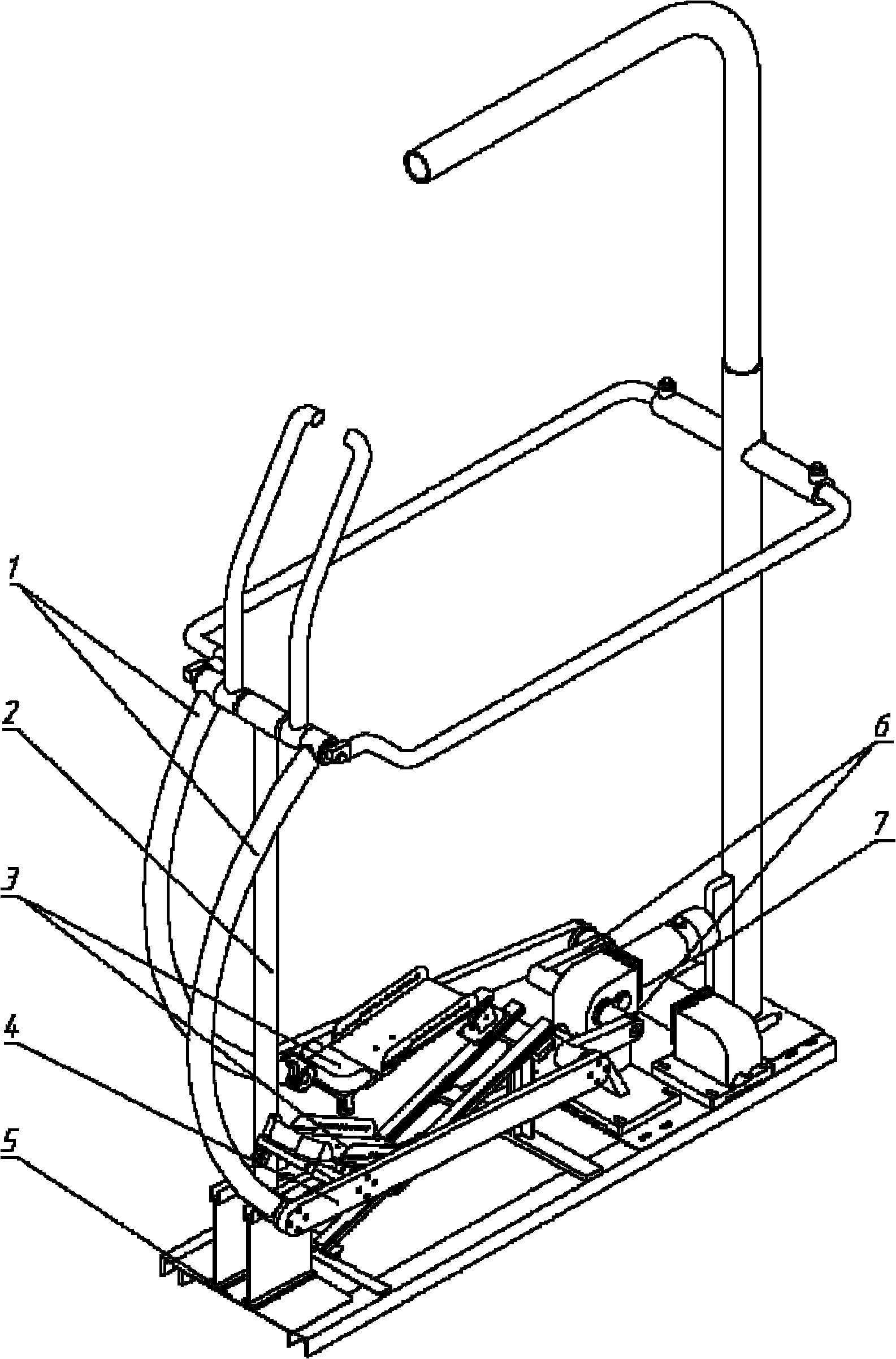
图1为本实用新型的三维图;Fig. 1 is the three-dimensional figure of the utility model;
图2为本实用新型的趾骨关节康复机构的三维图1;Fig. 2 is the three-dimensional diagram 1 of the phalanx joint rehabilitation mechanism of the present invention;
图3为本实用新型的趾骨关节康复机构的三维图2;Fig. 3 is a three-dimensional diagram 2 of the phalanx joint rehabilitation mechanism of the present invention;
图4为滑轮与滑槽刚接触时的正视图;Fig. 4 is the front view when the pulley is just in contact with the chute;
图5为前后脚踏板弯曲角度最大时的正视图;Fig. 5 is the front view when the bending angle of the front and rear pedals is the largest;
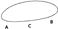
图6为合页处的轨迹曲线。Figure 6 is the trajectory curve at the hinge.
具体实施方式 Detailed ways
下面结合附图举例对本实用新型做更详细地描述:The utility model is described in more detail below in conjunction with accompanying drawing example:
结合图1~6,一种踏板式步态康复训练器趾骨关节康复机构。趾骨关节康复机构主要为踏板式步态康复训练器的脚踏板部分。踏板式步态康复训练器主要结构包括底板、左右2套成180°对称布置的步态机构、左右2套对称布置的踝关节运动机构、左右2套趾骨康复机构、位于机构后部的吊绳机构、位于前端的把手和前后分别固定于支柱和把手前轴的围栏机构。其中,底板5为平面框架式结构,前端连接有立式摇杆支柱2,后端固定有力矩电机7。步态机构由力矩电机7、曲柄6、左右两套曲柄连杆机构4、弯杆1和两套趾骨关节康复机构3组成;力矩电机的减速器轴对称,分别固连有成180°对称的曲柄;弯杆1一端与立式摇杆支柱2通过轴承铰链连接,另一端与连杆4通过连接轴、轴承铰链连接;连杆4另一端铰链连接于曲柄6;连杆4某个位置(本实施方式设定为四分之一处)与趾骨关节康复机构3铰链连接。力矩电机与曲柄固连,力矩电机通过曲柄带动连杆和摇杆摆动,进而带动与连杆铰链连接的、后端与直线轴承铰链连接、前端与限位部分的滑槽相配合的脚踏板做平面运动,这样来实现步态康复运动。1-6, a pedal type gait rehabilitation trainer phalanx joint rehabilitation mechanism. The phalanx joint rehabilitation mechanism is mainly the pedal part of the pedal type gait rehabilitation trainer. The main structure of the pedal type gait rehabilitation trainer includes a base plate, 2 sets of left and right gait mechanisms arranged symmetrically at 180°, 2 sets of left and right ankle joint movement mechanisms arranged symmetrically, 2 sets of left and right phalanx rehabilitation mechanisms, and a sling located at the rear of the mechanism A mechanism, a handle positioned at the front end, and a fence mechanism respectively fixed on the pillar and the front axle of the handle at the front and rear. Wherein, the bottom plate 5 is a plane frame structure, the front end is connected with a vertical rocker support 2, and the rear end is fixed with a torque motor 7. The gait mechanism is composed of a torque motor 7, a crank 6, two sets of crank linkage mechanisms 4 on the left and right, a bending rod 1 and two sets of phalanx joint rehabilitation mechanisms 3; Crank; one end of the curved rod 1 is connected to the vertical rocker pillar 2 through a bearing hinge, and the other end is connected to the connecting rod 4 through a connecting shaft and a bearing hinge; the other end of the connecting rod 4 is hinged to the crank 6; a certain position of the connecting rod 4 ( The present embodiment is set as a quarter) is hingedly connected with the phalanx joint rehabilitation mechanism 3. The torque motor is fixedly connected to the crank, and the torque motor drives the connecting rod and the rocker to swing through the crank, and then drives the pedal that is hingedly connected with the connecting rod, the rear end is hinged with the linear bearing, and the front end matches the chute of the limit part Do plane movement, so as to achieve gait rehabilitation movement.
趾骨关节康复机构,它是由前脚板部分、后脚板部分、支撑柱部分、位置限制部分、弹簧拉回装置组成前脚板和后脚板铰接在一起构成转动副。其特征是:所述的前脚板部分主要为焊接成型的前脚板8,周边固定着防护框;其底固定连接有长弹簧轴9;长弹簧轴9一段有固定弹簧的凹槽,一端和滑轮10通过销轴和轴承铰链连接。所述的后脚板部分主要为焊接成型的后脚板16,其周边固定着防护框;两边的防护框可以固定脚面绑带;前脚板和后脚板通过合页11铰接在一起,合页11通过紧定螺钉固定在前后脚踏板上,,前脚板与后脚板接触部分为上为一定角度的斜角、下半部直角,以达到一个方向限位的目的。后脚踏板前部固定连接有短弹簧轴12;短弹簧轴12一端有凹槽,通过凹槽长弹簧轴9和短弹簧轴12通过弹簧相连,起到使脚踏板保持平面的作用;后脚板16下部通过紧定螺钉和耳朵17固连;耳朵17和直线轴承连接块18通过销轴和轴承铰链连接;直线轴承连接块18与直线轴承的滑块16固连;滑块19套在滑轨20上。所述的直线轴承部分即为直线轴承的滑块19和滑轨20,后脚踏板的后侧和直线轴承相连,来完成踝关节的运动轨迹。滑轨20前后分别通过紧钉螺钉固连在滑轨支撑架21上;滑轨支撑架21固连在机构的地板上。所述的支撑柱部分由通过轴承铰链连接在一起的支撑块13和支撑轴14组成。支承轴14一侧连接机构的连杆上。所述的位置限制部分是由焊接在一起的位置限定槽和支撑架组成的限位槽15,限位槽15的支架底部与机构的底板5通过紧定螺钉固连,限位槽15的位置限定槽与滑轮10相配合,在脚踏板达到限定位置时与其相接处配合,滑轮接触滑槽,在滑槽中运动,使前脚踏板绕着合页的轴线运动,这样使前脚踏板8和后脚踏板16成一定的微小角度,达到趾骨关节在支撑期的弯曲效果;位置限定槽的槽面成一定的角度,以达到真实的体现趾骨弯曲的角度。The phalanx joint rehabilitation mechanism is composed of a front foot plate, a rear foot plate, a support column, a position limiting part, and a spring pull-back device, and the front foot plate and the rear foot plate are hinged together to form a revolving pair. It is characterized in that: the front foot plate part is mainly the
如图4、5、6所示为趾骨关节康复装置在趾骨关节处动作的正视图。前脚板和后脚板通过合页11铰接在一起,合页11通过紧定螺钉固定在前后脚踏板上,前脚板与后脚板接触部分为上为一定角度的斜角、下半部直角,以达到一个方向限位的目的。限位槽15的位置限定槽与滑轮10相配合,趾骨关节正好与合页的中心线对其,在脚踏板达到限定位置时与其相接处配合,滑轮接触滑槽,在滑槽中运动,使前脚踏板绕着合页的轴线运动,这样使前脚踏板8和后脚踏板16成一定的微小角度,这样因为趾骨关节正好与脚踏板弯曲的轴线相对其,从而带动了趾骨关节运动。图6中的ACB为趾骨关节动作范围,这段范围前脚踏板与后脚踏板以折页中线弯曲,有角度,并随着机构的动作而变化,BA即为上半椭圆前后脚踏板在同一直线上,没有角度其中A处即为滑轮刚接触滑槽时的位置(图4);B处为滑槽与滑轮接触式前后脚踏板发生最大角度时的位置(图5);Figures 4, 5 and 6 are front views of the phalanx joint rehabilitation device in action at the phalanx joint. The front foot plate and the rear foot plate are hinged together through the
本实用新型工作时,上位机将预先给定的步态数据转变成控制信号控制力矩电机的转动,进而带动患者下注相对应关节的转动。当患者进行步态康复训练时,整个摆动相和支撑相的早期(脚跟着地到跖骨着地),预紧弹簧使得前脚板和后脚板处于同一平面上。此阶段足底力主要集中在脚跟处。在支撑相中期(脚跟离地到另一侧脚跟着地)前脚板相对于地面保持水平,与后脚板发生相对转动且夹角由180°变到极小值。角度变化值是通过位置限定槽的倾斜角度来改变的,以达到正常人步行时支撑期趾骨的弯曲角度。此阶段脚跟处足底力变小,同时跖骨处足底力增大到极大值。在支撑相末期(至足趾离地前)前脚板由相对于地面的水平位置转变为与后脚板处于同一平面。与后脚板相对夹角由极小值变为180°。此阶段人体重心由一侧足底转向另一侧足底,跖骨处足底力变小,另一侧脚跟处足底力增大。整个步态周期中,整体机构的连杆带动脚踏板进行步态的轨迹运动,后脚踏板的后部与滑块相连,使得脚踏板绕着支承轴上下摆动,改变步态周期中后脚踏板与地面的夹角以达到踝骨关节的步态运动。When the utility model works, the upper computer converts the predetermined gait data into control signals to control the rotation of the torque motor, and then drives the rotation of the corresponding joints of the patient. When the patient performs gait rehabilitation training, during the entire swing phase and the early stage of the stance phase (heel strike to metatarsal strike), the preloaded spring keeps the front and rear feet on the same plane. At this stage, the plantar force is mainly concentrated on the heel. In the middle of the support phase (heel off the ground to the other side of the heel on the ground), the front foot plate remains horizontal relative to the ground, and the relative rotation occurs with the rear foot plate, and the included angle changes from 180° to a minimum value. The angle change value is changed by the inclination angle of the position-limiting groove, so as to achieve the bending angle of the phalanx in the stance phase when a normal person walks. At this stage, the plantar force at the heel becomes smaller, and at the same time, the plantar force at the metatarsal bone increases to a maximum. At the end of the stance phase (before toe-off) the forefoot changes from being horizontal relative to the ground to being on the same plane as the rear. The angle relative to the rear foot plate changes from a minimum value to 180°. At this stage, the center of gravity of the human body shifts from one sole of the foot to the other, the plantar force at the metatarsal bone becomes smaller, and the plantar force at the heel on the other side increases. During the entire gait cycle, the connecting rod of the overall mechanism drives the pedals to move along the trajectory of the gait, and the rear part of the rear pedals is connected with the slider to make the pedals swing up and down around the support shaft, changing the rear pedals in the gait cycle. The angle with the ground to achieve gait movement at the ankle joint.
Claims (6)
Priority Applications (1)
| Application Number | Priority Date | Filing Date | Title |
|---|---|---|---|
| CN201120201701U CN202128671U (en) | 2011-06-15 | 2011-06-15 | Phalanx knuckle rehabilitating mechanism of pedal type tread rehabilitation trainer |
Applications Claiming Priority (1)
| Application Number | Priority Date | Filing Date | Title |
|---|---|---|---|
| CN201120201701U CN202128671U (en) | 2011-06-15 | 2011-06-15 | Phalanx knuckle rehabilitating mechanism of pedal type tread rehabilitation trainer |
Publications (1)
| Publication Number | Publication Date |
|---|---|
| CN202128671U true CN202128671U (en) | 2012-02-01 |
Family
ID=45517457
Family Applications (1)
| Application Number | Title | Priority Date | Filing Date |
|---|---|---|---|
| CN201120201701U Expired - Lifetime CN202128671U (en) | 2011-06-15 | 2011-06-15 | Phalanx knuckle rehabilitating mechanism of pedal type tread rehabilitation trainer |
Country Status (1)
| Country | Link |
|---|---|
| CN (1) | CN202128671U (en) |
Cited By (12)
| Publication number | Priority date | Publication date | Assignee | Title |
|---|---|---|---|---|
| CN102218005A (en) * | 2011-06-15 | 2011-10-19 | 哈尔滨工程大学 | Phalanx joint rehabilitation mechanism of pedal gait rehabilitation trainer |
| CN102784044A (en) * | 2012-08-13 | 2012-11-21 | 昆山市工业技术研究院有限责任公司 | Walking recovery machine |
| CN103230334A (en) * | 2013-04-26 | 2013-08-07 | 哈尔滨工程大学 | Ankle flexion and extension rehabilitation training machine |
| CN103301006A (en) * | 2013-06-26 | 2013-09-18 | 中国科学院合肥物质科学研究院 | Rehabilitation gait track generator |
| CN103505327A (en) * | 2013-08-23 | 2014-01-15 | 洛阳希诺能源科技有限公司 | Fitness wheelchair |
| CN103845185A (en) * | 2014-02-28 | 2014-06-11 | 天津大学 | Household small-size lower limb rehabilitation training robot |
| CN103961240A (en) * | 2014-05-16 | 2014-08-06 | 哈尔滨工程大学 | Ankle foot rehabilitation training device and balance training system |
| CN104905942A (en) * | 2015-07-04 | 2015-09-16 | 苏州塔可盛电子科技有限公司 | Hemiplegia recovery device |
| CN106963598A (en) * | 2017-04-10 | 2017-07-21 | 丽水市日峰电器有限公司 | A kind of adjustable legs and feet telecontrol equipment of rehabilitation machines |
| CN107582331A (en) * | 2017-10-17 | 2018-01-16 | 璧靛惫 | A kind of gait rehabilitation trainer |
| GB2561604A (en) * | 2017-04-21 | 2018-10-24 | Jaguar Land Rover Ltd | Gait training apparatus |
| CN110353946A (en) * | 2019-08-01 | 2019-10-22 | 新乡医学院第一附属医院(河南省结核病医院) | A kind of leg training healing robot |
-
2011
- 2011-06-15 CN CN201120201701U patent/CN202128671U/en not_active Expired - Lifetime
Cited By (18)
| Publication number | Priority date | Publication date | Assignee | Title |
|---|---|---|---|---|
| CN102218005A (en) * | 2011-06-15 | 2011-10-19 | 哈尔滨工程大学 | Phalanx joint rehabilitation mechanism of pedal gait rehabilitation trainer |
| CN102218005B (en) * | 2011-06-15 | 2013-02-06 | 哈尔滨工程大学 | Rehabilitation mechanism of phalanx joint of pedal type gait rehabilitation trainer |
| CN102784044A (en) * | 2012-08-13 | 2012-11-21 | 昆山市工业技术研究院有限责任公司 | Walking recovery machine |
| CN102784044B (en) * | 2012-08-13 | 2014-12-10 | 昆山市工业技术研究院有限责任公司 | Walking recovery machine |
| CN103230334A (en) * | 2013-04-26 | 2013-08-07 | 哈尔滨工程大学 | Ankle flexion and extension rehabilitation training machine |
| CN103230334B (en) * | 2013-04-26 | 2015-03-11 | 哈尔滨工程大学 | Ankle flexion and extension rehabilitation training machine |
| CN103301006B (en) * | 2013-06-26 | 2014-11-05 | 中国科学院合肥物质科学研究院 | Rehabilitation gait track generator |
| CN103301006A (en) * | 2013-06-26 | 2013-09-18 | 中国科学院合肥物质科学研究院 | Rehabilitation gait track generator |
| CN103505327A (en) * | 2013-08-23 | 2014-01-15 | 洛阳希诺能源科技有限公司 | Fitness wheelchair |
| CN103845185A (en) * | 2014-02-28 | 2014-06-11 | 天津大学 | Household small-size lower limb rehabilitation training robot |
| CN103961240A (en) * | 2014-05-16 | 2014-08-06 | 哈尔滨工程大学 | Ankle foot rehabilitation training device and balance training system |
| CN103961240B (en) * | 2014-05-16 | 2016-09-14 | 哈尔滨工程大学 | Ankle foot healing training devices and balance training system |
| CN104905942A (en) * | 2015-07-04 | 2015-09-16 | 苏州塔可盛电子科技有限公司 | Hemiplegia recovery device |
| CN106963598A (en) * | 2017-04-10 | 2017-07-21 | 丽水市日峰电器有限公司 | A kind of adjustable legs and feet telecontrol equipment of rehabilitation machines |
| CN106963598B (en) * | 2017-04-10 | 2023-08-04 | 丽水市日峰电器有限公司 | An adjustable leg and foot movement device for a rehabilitation machine |
| GB2561604A (en) * | 2017-04-21 | 2018-10-24 | Jaguar Land Rover Ltd | Gait training apparatus |
| CN107582331A (en) * | 2017-10-17 | 2018-01-16 | 璧靛惫 | A kind of gait rehabilitation trainer |
| CN110353946A (en) * | 2019-08-01 | 2019-10-22 | 新乡医学院第一附属医院(河南省结核病医院) | A kind of leg training healing robot |
Similar Documents
| Publication | Publication Date | Title |
|---|---|---|
| CN105167959B (en) | A kind of multi-functional gait rehabilitation trainer | |
| CN101829005B (en) | A foot pedal device for gait rehabilitation robot with metatarsal joints | |
| CN105616113B (en) | A kind of passive energy storage foot mechanism for lower limb assistance exoskeleton | |
| CN106901947B (en) | Wearable lower limb exoskeleton assisted walking robot mechanism | |
| CN205198395U (en) | Wearable low limbs ectoskeleton helping hand walking robot mechanism | |
| CN107982026B (en) | A multi-part rehabilitation chair for lower limbs | |
| CN205163560U (en) | Multi -functional gait rehabilitation training device | |
| CN110478196B (en) | A lower limb rehabilitation training robot | |
| CN108904225A (en) | Step device and walking rehabilitation training robot | |
| CN103126851A (en) | Gait training mechanical leg | |
| CN105853041B (en) | Leg correction orthopedic appliance | |
| CN113599782B (en) | Lower limb walking rehabilitation training machine | |
| CN102218005B (en) | Rehabilitation mechanism of phalanx joint of pedal type gait rehabilitation trainer | |
| CN105030486B (en) | A kind of walk-aiding exoskeleton unpowered mechanical foot | |
| CN103278278B (en) | Strength tester for foot metatarsophalangeal joints | |
| CN109925164B (en) | Rope-driven inner foot mechanism for lower limb rehabilitation robot | |
| CN209519072U (en) | Stepping device and walking rehabilitation training robot | |
| CN108852741B (en) | Four-bar linkage helping hand running gear | |
| CN2925455Y (en) | Standing lower limb rehabilitation training machine | |
| CN111671624A (en) | A wearable metatarsophalangeal joint walking assist device | |
| CN103566542B (en) | Device for driving person to carry out gait training by binding feet and shanks | |
| CN210408942U (en) | Rope-driven inner foot mechanism for lower extremity rehabilitation robot | |
| CN219941152U (en) | A gait rehabilitation training device | |
| CN206950253U (en) | Correction type foot pedal apparatus for lower limb rehabilitation training device | |
| CN109925165B (en) | Rope-driven "4+2" lower limb rehabilitation robot |
Legal Events
| Date | Code | Title | Description |
|---|---|---|---|
| C14 | Grant of patent or utility model | ||
| GR01 | Patent grant | ||
| AV01 | Patent right actively abandoned |
Granted publication date: 20120201 Effective date of abandoning: 20130306 |
|
| RGAV | Abandon patent right to avoid regrant |