The utility model content
The goal of the invention of the utility model provides a kind of combined drill; Drill bit is composited by big deviation angle flywheel knife cutting unit and stationary cutting structure, and big deviation angle flywheel knife cutting unit makes cutting teeth on the flywheel knife alternately to scrape butt formula fractured rock, cutting teeth on the stationary cutting structure and the cutting teeth acting in conjunction on the flywheel knife; Intersect and cut bottom rock; Form netted shaft bottom pattern, can when increasing drilling life of bit, improve efficiency of breaking rock.
The technical scheme of the utility model is following:
A kind of combined drill; Comprise drill body and at least one group of flywheel knife cutting unit that is arranged on the said drill body; Said flywheel knife cutting unit comprises the flywheel knife and the wheel palm; The said palm of taking turns is arranged on the drill body, and said flywheel knife is arranged on the axle journal of the wheel palm to form with the wheel palm and is rotationally connected, and on said flywheel knife, is furnished with and effluxes the cutting gear ring; It is characterized in that: the scope of the offset angle of said flywheel knife be 20 °≤| α |≤90 °, said drill body is provided with at least one group and comprises the fixedly stationary cutting structure of cutting teeth.
The described a kind of combined drill of the utility model, its said flywheel knife cutting unit has two groups at least, wherein has at least the deviation angle of flywheel knife of deviation angle and other group flywheel knife cutting unit of flywheel knife of one group of flywheel knife cutting unit unequal.
The described a kind of combined drill of the utility model, its said flywheel knife cutting unit has two groups at least, wherein has at least the external diameter size of flywheel knife of one group of flywheel knife cutting unit unequal with the external diameter size of the flywheel knife of other group flywheel knife cutting unit.
The described a kind of combined drill of the utility model, its said flywheel knife cutting unit has two groups at least, wherein has at least the axial rake of flywheel knife of axial rake and other group flywheel knife cutting unit of flywheel knife of one group of flywheel knife cutting unit unequal.
The described a kind of combined drill of the utility model, its said flywheel knife cutting unit has two groups at least, wherein has at least the cloth space width of one group of cutting teeth on the flywheel knife cutting unit flywheel knife and the cloth space width on other group flywheel knife cutting unit flywheel knife inequality.
The described a kind of combined drill of the utility model, the cutting teeth unequal-interval on its said same flywheel knife is arranged.
In the said structure; The offset angle of said flywheel knife=
; Wherein s is the wheelbase that moves of flywheel knife, and c is the stand-off of flywheel knife.Like Fig. 3, Fig. 4, shown in Figure 5, AB is a drill bit central axis, and CD is the flywheel knife central axis, is flywheel knife pole axis face A through flywheel knife axis CD and the face that is parallel to drill axis AB
1, A
2Be through drill axis AB and perpendicular to flywheel knife pole axis face A
1The plane, A
3Be to pass through drill axis AB and be parallel to flywheel knife pole axis face A
1The plane.The point that characterizes each cutting teeth position coordinates on the flywheel knife is the anchor point of each cutting teeth, and the anchor point of cylindrical PDC tooth is the central point of the diamond working face of tooth, and the anchor point of other type cutting teeth is arranged on certain specified point of tooth.Flywheel knife effluxes the plane A at each cutting teeth anchor point place on the gear ring
4Be the flywheel knife reference plane, flywheel knife reference plane A
4With the intersection point E of flywheel knife axis CD be the flywheel knife reference point.Cross some E and make vertical line to drill axis AB, intersection point is F.Flywheel knife stand-off c be flywheel knife reference point E to the plane A
2Distance; Flywheel knife moves wheelbase s and is drill axis AB and flywheel knife pole axis face A
1Between distance, and regulation is seen to the bit adapter hand of spiral along drill axis from flywheel knife (promptly against drill bit drilling direction see) to make flywheel knife reference point E be positioned at plane A
2The left side, if this moment is pole axis face A
1The A on the plane
3The below then is the axle of shuffling, otherwise, then be the negative axle (shown in Figure 5 for shuffling axle, shown in Figure 6 is the negative axle that moves) that moves; The offset angle of flywheel knife is straight line EF and plane A
3Between angle, promptly have offset angle=
, a hour offset angle α that shuffles bears and moves a hour offset angle α for negative for just; The axial rake β of flywheel knife is flywheel knife axis CD and perpendicular to the angle between the plane of drill axis AB.
When drill bit under the driving of the pressure of the drill, moment of torsion during rotary drilling; Flywheel knife is rotating and outside axis is done axial feed motion around drill axis with drill body; Also can rotate motion, promptly can rotate around the center line of journal (being the flywheel knife axis) of the wheel palm with respect to drill body.If the deviation angle of flywheel knife equals zero; The axis of flywheel knife and drill axis intersect; Flywheel knife can roll on bottom rock with pure rolling or the mode that approaches pure rolling, and its mean speed equals or is approximately equal to by drill speed and the determined pure rolling speed of flywheel knife rolling track radius of circle.At this moment, flywheel knife will be that instantaneous center of rotation relatively rotates with the application point of the cutting teeth that acts on mutually with bottom rock, not have relative slippage between cutting teeth and the rock.If the deviation angle of flywheel knife is not equal to zero, then the axis of flywheel knife and drill axis are no longer crossing, but the space is staggered, and the pure rolling condition of flywheel knife is no longer satisfied.At this moment, flywheel knife still can roll on rock, but its rolling speed no longer equals pure rolling speed, but is lower than pure rolling speed.Relative slippage can take place with rock in the cutting teeth on the flywheel knife in rolling across the process of rock, thereby form cutting teeth scraping of rock cut or shear action.
When deviation angle was non-vanishing, the relative slippage (scrape cut) of the cutting teeth on the flywheel knife on bottom rock comprised two parts: the first, and radial slippage.The process of cutting teeth on the flywheel knife from beginning rock cutting (incision) to disengaging rock cutting (cutting out); Cutting point on the rock is different with radially (drill bit radially) position that cuts out a little; Show cutting teeth with process that rock contacts in radial slippage has taken place; Cutting point and cut out a little between radial distance, represented the radial slippage amount of cutting teeth.Deviation angle is big more, and cutting teeth incision, the radial distance between cutting out a little are big more, and the radial slippage amount is also just big more.The second, circumferentially slippage.When drill speed was confirmed, the wheel body speed ratio had determined the cutwork time (promptly from the incision rock to time that the cutting at one time process that cuts out rock is experienced) of cutting teeth.Because the wheel body speed ratio when deviation angle is non-vanishing is lower than the wheel body speed ratio under the pure rolling condition, the rotating speed of flywheel knife is slack-off, so the cutwork time of cutting teeth is elongated, thereby cutting teeth is produced along the slippage of circumferential (drill bit circumferencial direction).The wheel body speed ratio is more little, and the cutwork time of cutting teeth is long more, and circumferentially slippage is also just big more.The total sliding velocity of cutting teeth on bottom rock is that radial slippage speed is synthetic with the vector of circumferential sliding velocity.According to the motion feature of bit body and flywheel knife, cutting teeth is the similar helix shape of when negative (deviation angle for) along (deviation angle is correct time) from outside to inside of drill bit direction of rotation or from inside to outside at the slippage on the bottom rock (scrape and cut) track.
Flywheel knife move that wheelbase s increases or stand-off c reduces, all cause the flywheel knife offset angle to increase, the former capital can increase the radial slippage and circumferentially slippage of cutting teeth in the shaft bottom, promptly increases the total slippage of cutting teeth in the shaft bottom.
The offset angle of above-mentioned flywheel knife=
, thus make 20 °≤| α | realize that better cutting teeth is to scrape the broken rock of the mode of cutting for≤90 °.Concretely, certain when outside diameter, when the flywheel knife diameter remained unchanged, what increase flywheel knife moved wheelbase s, and the stand-off c of flywheel knife will correspondingly reduce.
In the utility model; The broken rock mode that has adopted stationary cutting structure to combine with flywheel knife: flywheel knife and stationary cutting structure are the cutting structure with the broken bottom rock of cutting way; Cutting teeth on the stationary cutting structure is scraped the Cutting trajectory that cuts out concentric circles on bottom rock, and the cutting teeth on the flywheel knife is scraped on bottom rock and cut out from outside to inside or spirality Cutting trajectory from inside to outside.Two cover Cutting trajectories intersect each other, and its effect is to form netted shaft bottom pattern, helps the effective wedging of cutting teeth to rock, helps the fragmentation of rock, so can effectively improve the efficiency of breaking rock of drill bit.
As far as fixed cutter drill bits; Cutting teeth cuts bottom rock continuously; The rate of wear difference of the PDC tooth on the different radial zones of drill bit is fairly obvious, obviously regional faster than the heart portion tooth of the rate of wear of general bit exterior zone (particularly outer 1/3 zone of drill bit radius) cutting teeth.Cutting teeth on the flywheel knife in the utility model can play special booster action with failed areas to the cutting teeth of fixed cutter drill bits is easy to wear.Cutting teeth on the flywheel knife is scraped in turn with the form that slowly replaces and is cut brokenly rock, the actual participation cutwork of each cutting teeth obviously be less than the duration of runs of drill bit total time, so the rate of wear of cutting teeth significantly reduces.The reduction meeting of cutter-wear rate causes direct influence to the cutting teeth on the stationary cutting structure on the flywheel knife, slows down its rate of wear.Cutting teeth position the most easy to wear is corresponding on the intersection cutting zone in shaft bottom or netted cutting zone and the drill bit, helps reducing the service load of this position cutting teeth, reduces the rate of wear.So the combined drill of the utility model is easier to realize the balance abrasion of cutting teeth on the one hand, can significantly improve the working life of drill bit on the other hand.
The alternately cutwork mode of the cutting teeth on the flywheel knife helps the cooling of cutting teeth (particularly PDC tooth), avoids or reduced the generation of the thermal wear phenomenon of aggravating of causing wearing and tearing owing to temperature is too high.
As far as conventional fixed teeth drill bit, increase the rate of wear that cloth tooth density can be slowed down cutting teeth, increase the working life of drill bit, but also can reduce the rate of penetration of drill bit simultaneously.In the utility model, can arrange more cutting teeth on the flywheel knife, increased cutting teeth quantity, and the cutting teeth on the flywheel knife can take turns to operate.Because that participates in rock cutting on the flywheel knife simultaneously has only the part cutting teeth, so effective work number of teeth of drill bit is significantly less than total cutting number of teeth of drill bit.In other words, the flywheel knife cutting structure can be when increasing total cutting number of teeth (increasing cloth tooth density), and the number of teeth that maintenance is worked simultaneously is constant or constant basically.Its effect is when keeping the drill bit rate of penetration, to make the working life of drill bit be able to prolong.Like this, the contradiction that in drill bit design, prolongs between bit life and the raising drilling speed can significantly be alleviated.
Because the cutting teeth on the flywheel knife is with cutting way (cut mode) fractured rock; The required axial weight on bit of flywheel knife is less relatively; The pressure of the drill fluctuating range is also less; And the wheel body speed ratio of combined bits is lower than tricone bit, thereby combined bits can reach the bearing life higher than tricone bit.
The thinking of the utility model is: the mode of moving wheelbase s, reducing the stand-off c of flywheel knife through increasing flywheel knife increases the flywheel knife offset angle; And make its 20 °≤| α | in≤90 ° of scopes; Reach the cutting teeth that increases on the flywheel knife radial slippage amount in the shaft bottom; And reduce the wheel body speed ratio simultaneously, increase cutting teeth the shaft bottom scrape the time of cutting and circumferential slippage, thereby increase cutting teeth total slippage (scraping the amount of cutting) on bottom rock.Like this; When drill bit is worked in the shaft bottom; Cutting teeth on the flywheel knife is with the rock of speed incision slowly; And scrape at relative bottom rock under the drive of bit body and slowly to cut out again after cutting one section long distance, thereby realize that the cutting teeth on the flywheel knife scrapes the purpose of cutting or cutting brokenly rock in turn with the form that slowly replaces in the shaft bottom.Be equipped with simultaneously and have the fixedly stationary cutting structure of cutting teeth; The acting in conjunction effect of two cover Cutting trajectories is to form the intersection cutting zone in the shaft bottom; Help the effective wedging of cutting teeth, help the fragmentation of rock, so can effectively improve the efficiency of breaking rock of drill bit rock.
The utility model compared with prior art, its beneficial effect is:
(1) the present invention combines flywheel knife with fixing cutting unit; On bottom rock, formed two cover Cutting trajectories, its effect is to form intersection cutting zone and netted shaft bottom pattern in the shaft bottom, and cutting force and the cutting power of cutting teeth under this condition all reduces; Help slowing down the rate of wear of cutting teeth; Also help the effective wedging of cutting teeth, help the fragmentation of rock, can significantly improve the efficiency of breaking rock of drill bit rock.Particularly when the exterior zone the most easy to wear of cutting teeth on the intersection cutting zone in shaft bottom or mesh-like area and the drill bit is corresponding; Can reduce the cutting force and the cutting power of this zone cutting teeth; Slow down its rate of wear, this is very useful for improving efficiency of breaking rock and the working life of drill bit when bad ground creeps into.
(2) the cutting teeth alternation on the flywheel knife reduces or has avoided fixed cutter drill bits because of the drill bit initial failure that the minority cutting teeth lost efficacy and brings, and has prolonged drilling life of bit.
(3) the cutting teeth alternation on the flywheel knife, the cutting teeth wearing and tearing are even, and the ability to work of each cutting teeth can be fully used.
(4) the cutting teeth alternation on the flywheel knife, good cooling results is difficult for taking place thermal wear.
(5) combined drill can utilize diamond composite components such as PDC composite sheet as cutting teeth, and the working life of tooth and stock-removing efficiency all are superior to single-cone rotary drill bit.
The pressure of the drill required when (6) combined drill creeps into is little, and the suffered load of bearing is little, and the load fluctuation amplitude is low; The wheel body speed ratio of drill bit is low, lacks so bearing relatively rotates slowly, generates heat.So the bearing working life-span of combined drill is longer than the tricone bit of equal specification.
For reducing and avoid the generation of cutting teeth on the flywheel knife " with the rail cutting " phenomenon, the utility model can take following further improvement project to realize:
Said flywheel knife cutting unit has two groups at least, wherein has at least the deviation angle of flywheel knife of deviation angle and other group flywheel knife cutting unit of flywheel knife of one group of flywheel knife cutting unit unequal.
Said flywheel knife cutting unit has two groups at least, wherein has at least the external diameter size of flywheel knife of one group of flywheel knife cutting unit unequal with the external diameter size of the flywheel knife of other group flywheel knife cutting unit.
Said flywheel knife cutting unit has two groups at least, wherein has at least the axial rake of flywheel knife of axial rake and other group flywheel knife cutting unit of flywheel knife of one group of flywheel knife cutting unit unequal.
Said flywheel knife cutting unit has two groups at least, wherein has at least the cloth space width of one group of cutting teeth on the flywheel knife cutting unit flywheel knife and the cloth space width on other group flywheel knife cutting unit flywheel knife inequality.
Cutting teeth unequal-interval on the said same flywheel knife is arranged.
It is inequality with the cloth space width of inboard cutting gear ring to efflux the cutting gear ring on the said same flywheel knife.
The beneficial effect of such scheme is:
(7) the cutting teeth unequal-interval on unequal, the flywheel knife of the deviation angle of flywheel knife external diameter size unequal, flywheel knife axial rake unequal, flywheel knife arrange, respectively arrange on the flywheel knife cloth space width of cutting teeth inequality or (with) the cloth space width and the cloth space width on other flywheel knife of cutting teeth on the flywheel knife be inequality; Can reduce and avoid the generation of cutting teeth " with the rail cutting " phenomenon on the flywheel knife in the drilling process; Make the cutting teeth on the flywheel knife scrape and cut brokenly rock along " phacolith " (rock band of convexity between the two broken grooves) of bottom rock; Help cutting teeth to the effective wedging of rock and the fragmentation of rock, so can effectively improve the efficiency of breaking rock of drill bit.
(8) adopt such scheme; Can reduce and avoid the generation of cutting teeth " with the rail cutting " phenomenon on the flywheel knife in the drilling process; Cutting teeth on the flywheel knife is scraped along " phacolith " of bottom rock cut brokenly rock, can reduce and avoid protruding " phacolith " wear damage the flywheel knife body.
To sum up, the cutting teeth among the present invention on the flywheel knife breaks rock alternately to scrape the form of cutting, and the cutting teeth on the matching and fixing cutting structure, on bottom rock, forms the intersection cutting zone; Efficiency of breaking rock is high, and wearing and tearing are even, good cooling results; The life-span of tooth is long, and the bearing working life-span is high, and drilling life of bit is long.
Description of drawings
The utility model will explain through example and with reference to the mode of accompanying drawing, wherein:
Fig. 1 is the structural representation of the utility model, and its flywheel knife cutting unit and stationary cutting structure are 2 groups, both alternate layouts.Among the figure: 1, drill body, 2, flywheel knife, 3, the wheel palm, 4, efflux the cutting gear ring, 7, nozzle, 8, stationary cutting structure, 8a, fixing cutting teeth;
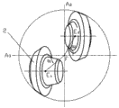
Fig. 2 is the view of the utility model when drill axis is overlooked (contrary drill bit drilling direction see);
Fig. 3 moves the sketch map of wheelbase s, stand-off c, offset angle and axial rake β for the flywheel knife geometric position parameter of the utility model;
Fig. 4 is that the flywheel knife of one group of cutting unit of the utility model is along the sectional view of flywheel knife pole axis face.Among the figure: 6, axle journal;
Fig. 5 is the sketch map of the utility model relative geometry position and the parameter s of flywheel knife on drill bit, c, α when drill axis is overlooked, the diagram deviation angle be on the occasion of;
Fig. 6 is the sketch map of the flywheel knife deviation angle of the utility model when unequal; Among the figure, α 1 ≠ α 2;
Fig. 7 is the sketch map of the flywheel knife external diameter size of the utility model when unequal; Among the figure, r1 ≠ r2;
Fig. 8 is the sketch map of the flywheel knife axial rake of the utility model when unequal; Among the figure, β 1 ≠ β 2;
Fig. 9 is the cutting teeth cloth space width anisochrouous sketch map on the flywheel knife of the utility model;
Figure 10 be the utility model drill bit under flywheel knife cutting unit and stationary cutting structure acting in conjunction, intersect in the shaft bottom and to scrape the netted scratch sketch map that cuts out.
The specific embodiment
Below in conjunction with accompanying drawing, the utility model is done detailed explanation.
For the purpose, technical scheme and the advantage that make the utility model is clearer,, the utility model is further elaborated below in conjunction with accompanying drawing and embodiment.Should be appreciated that specific embodiment described herein only in order to explanation the utility model, and be not used in qualification the utility model.
Like Fig. 1,2,3,4, shown in 5: a kind of combined drill, comprise drill body 1, flywheel knife 2, have the wheel palm 3 on the said drill body 1; Said flywheel knife 2 is installed in said the wheel on the palm 3 the axle journal 6; Form with the wheel palm 3 and to be rotationally connected, on said flywheel knife 2, be furnished with and efflux cutting gear ring 4, it is characterized in that: the scope of the offset angle of said flywheel knife 2 be 20 °≤| α |≤90 °; Drill body 1 is provided with stationary cutting structure 8, is consolidated with fixedly cutting teeth 8a on the stationary cutting structure 8.
The scope of the offset angle of flywheel knife 2 20 °≤| α | in the time of≤90 °, can realize that drill bit creeps into cutting teeth on the hour wheel cutter 2 and scrapes in turn with the form that slowly replaces and cut brokenly rock.Under the acting in conjunction of flywheel knife cutting unit and stationary cutting structure, two cover Cutting trajectories intersect each other, and drill bit is scraped in the shaft bottom and cut out netted broken pattern.
Shown in figure 10; Cutting teeth on the flywheel knife cutting unit is scraped and is cut out similar spiral yarn shaped scratch 10; Fixedly cutting teeth on the stationary cutting structure is scraped and is cut out circular concentric scratch 9, and flywheel knife cutting unit and stationary cutting structure cooperate can realize staggered complicated netted shaft bottom pattern.
For reducing and avoid the generation of cutting teeth " with the rail cutting " phenomenon on the flywheel knife, the utility model can adopt following embodiment:
Said flywheel knife cutting unit has two groups at least, wherein has at least the deviation angle of flywheel knife of deviation angle and other group flywheel knife cutting unit of flywheel knife of one group of flywheel knife cutting unit unequal.As shown in Figure 6, the deviation angle of two flywheel knives is unequal, α
1≠ α
2If the flywheel knife cutting unit is three groups, then the deviation angle of the flywheel knife in one group of flywheel knife cutting unit is α
1, other two groups all is α
2, α
1≠ α
2, one is α in perhaps other two groups
2, another is α
3, α
2≠ α
3
Said flywheel knife cutting unit has two groups at least, wherein has at least the external diameter size of flywheel knife of one group of flywheel knife cutting unit unequal with the external diameter size of the flywheel knife of other group flywheel knife cutting unit.As shown in Figure 7, the external diameter of two flywheel knives is unequal, r
1≠ r
2If the flywheel knife cutting unit is three groups, then the external diameter of the flywheel knife in one group of flywheel knife cutting unit is r
1, other two groups all is r
1, r
1≠ r
2, one is r in perhaps other two groups
2, another is r
3, r
2≠ r
3
Said flywheel knife cutting unit has two groups at least, wherein has at least the axial rake of flywheel knife of axial rake and other group flywheel knife cutting unit of flywheel knife of one group of flywheel knife cutting unit unequal.As shown in Figure 8, the axial rake of two flywheel knives is unequal, β
1≠ β
2If the flywheel knife cutting unit is three groups, then the axial rake of the flywheel knife in one group of flywheel knife cutting unit is β
1, other two groups all is β
2, β
1≠ β
2, one is β in perhaps other two groups
2, another is β
3, β
2≠ β
3
Said flywheel knife cutting unit has two groups at least, wherein has at least the cloth space width of one group of cutting teeth on the flywheel knife cutting unit flywheel knife and the cloth space width on other group flywheel knife cutting unit flywheel knife inequality.
Cutting teeth unequal-interval on the said same flywheel knife is arranged.As shown in Figure 9, the cloth space width on the flywheel knife between cutting teeth is unequal.
The above is merely the preferred embodiment of the utility model; Not in order to restriction the utility model; Any modification of being done within all spirit and principles at the utility model, be equal to replacement and improvement etc., all should be included within the protection domain of the utility model.