CN202276830U - Replaceable universal atomization head - Google Patents
Replaceable universal atomization head Download PDFInfo
- Publication number
- CN202276830U CN202276830U CN2011203775456U CN201120377545U CN202276830U CN 202276830 U CN202276830 U CN 202276830U CN 2011203775456 U CN2011203775456 U CN 2011203775456U CN 201120377545 U CN201120377545 U CN 201120377545U CN 202276830 U CN202276830 U CN 202276830U
- Authority
- CN
- China
- Prior art keywords
- liquid
- heating device
- seat
- conductive ring
- liquid guide
- Prior art date
- Legal status (The legal status is an assumption and is not a legal conclusion. Google has not performed a legal analysis and makes no representation as to the accuracy of the status listed.)
- Expired - Lifetime
Links
Images


Landscapes
- Electrostatic Spraying Apparatus (AREA)
Abstract
本实用新型公开了一种可更换的通用雾化头,加热装置固定于支撑座的雾化腔中,所述导液部件包括导液绳、导液嘴以及与导液嘴连为一体的导液嘴座,导液绳的一端从导液嘴座穿出后与加热装置连接,还包括一个导电环,所述支撑座固定在导电环腔体的中部后将连接于加热装置一端的导线压紧在导电环和支撑座之间;所述导液嘴和导液嘴座的内孔壁面上设有导液槽,导液嘴座的一端插入到导电环腔体的一端;在导电环腔体的另一端设有导电部件,该导电部件包括导电体和绝缘体,导电体固定在绝缘体上,导电体与连接于加热装置另一端的导线焊接,绝缘体紧固在导电环的腔体中,绝缘体上设有通气孔。本实用新型的可更换的通用雾化头具有结构简单、装配方便以及够防止干烧的优点。
The utility model discloses a replaceable universal atomizing head. The heating device is fixed in the atomizing chamber of the support seat. Liquid nozzle seat, one end of the liquid guide rope passes through the liquid guide nozzle seat and is connected to the heating device. It also includes a conductive ring. Closely between the conductive ring and the support seat; the inner hole wall of the liquid guide nozzle and the liquid guide nozzle seat is provided with a guide groove, and one end of the liquid guide nozzle seat is inserted into one end of the conductive ring cavity; in the conductive ring cavity The other end of the body is provided with a conductive part, the conductive part includes a conductor and an insulator, the conductor is fixed on the insulator, the conductor is welded to the wire connected to the other end of the heating device, the insulator is fastened in the cavity of the conductive ring, and the insulator There are ventilation holes on it. The replaceable universal atomizing head of the utility model has the advantages of simple structure, convenient assembly and the ability to prevent dry burning.
Description
技术领域 technical field
本实用新型涉及一种电子烟,具体涉及一种可更换的通用雾化头。The utility model relates to an electronic cigarette, in particular to a replaceable universal atomizing head.
背景技术 Background technique
电子烟现目前主要是在欧美一些发达国家使用比较广泛,主要是用来替代传统香烟。随着我国生活水平的不断提高。人们也在不断追求更高的生活质量,也逐渐认识到吸烟的严重危害性,戒烟逐步成为了一个共同的认识。所以像电子烟这种替代品,也逐渐受到人们的欢迎。Electronic cigarettes are currently widely used in some developed countries in Europe and the United States, mainly to replace traditional cigarettes. With the continuous improvement of our country's living standards. People are also constantly pursuing a higher quality of life, and gradually realize the serious harm of smoking, and smoking cessation has gradually become a common understanding. So alternatives like e-cigarettes are gradually gaining popularity.
电子烟与香烟有一样的外观、与香烟近似的味道,甚至比一般香烟的口味要多出很多,也像香烟一样能吸出烟、吸出味道,甚至比一般香烟的口味要多出很多,也像香烟一样能吸出烟、吸出味道跟感觉来。主要是用于戒烟和替代香烟。电子烟又是一种非燃烧的烟类替代型产品,它与普通香烟的某些特点相似,能够提神、满足吸烟者的快感和多年养成的使用习惯。但又与普通香烟有着本质上的不同,电子烟不燃烧、不含焦油、不含普通烟燃烧时产生的会导致呼吸系统与心血管系统疾病的460余种化学物质,从而去除了普通烟中的致癌物质。从而去除了普通烟中的致癌物质。不会对他人产生“二手烟”的危害及污染环境。E-cigarettes have the same appearance as cigarettes, taste similar to cigarettes, and even taste much more than ordinary cigarettes. Cigarettes can also suck out smoke, taste and feeling. Mainly used for smoking cessation and alternative cigarettes. E-cigarettes are also a non-combustible tobacco alternative product. It has some characteristics similar to ordinary cigarettes. It can refresh, satisfy smokers' pleasure and use habits developed over the years. However, it is essentially different from ordinary cigarettes. Electronic cigarettes do not burn, do not contain tar, and do not contain more than 460 kinds of chemical substances that can cause respiratory and cardiovascular system diseases when burned by ordinary cigarettes, thus eliminating the harmful substances in ordinary cigarettes. carcinogens. Thereby removing the carcinogens in ordinary smoke. It will not cause "second-hand smoke" harm to others and pollute the environment.
电子烟是由雾化器和烟杆两大部分组成。烟杆由PCB板,充电电池以及其他各种电路组成,雾化器由雾化装置和烟弹组成。授权公告号为:CN201878765U的实用新型专利公开了一种雾化器(见图4),该雾化器的雾化装置包括雾化器主体330、吸液嘴座310、发热装置311以及导液组件,吸液嘴座一端设有雾化腔313,吸液嘴座的另一端设有与雾化腔连通的通气孔314,所述发热装置固定在该雾化腔中;导液组件包括吸液嘴以及导液绳320,吸液嘴的一端插入到储液盒的储液空腔中,吸液嘴与储液盒的接触部位形成液密封,吸液嘴的另一端与吸液嘴座的雾化腔连通,所述导液绳缠绕在发热装置311上,导液绳的两个端部被引入到吸液嘴中。Electronic cigarettes are composed of two parts: an atomizer and a cigarette rod. The pod is composed of PCB board, rechargeable battery and various other circuits, and the atomizer is composed of atomizing device and pod. The authorized announcement number is: CN201878765U utility model patent discloses an atomizer (see Figure 4), the atomization device of the atomizer includes an atomizer
雾化装置30的固定在壳体10另一端的连接组件:该连接组件包括雾化器主体330、通过导线连接发热装置311的接触导体331以及接触导体底座332。雾化器主体330的位于壳体中的一端形成有容纳并保持雾化组件的腔体,套管312及其他雾化组件的零件固定在这个腔体中,套管312与腔体采用过盈的方式进行配合。雾化器主体的侧壁上设有与腔体连通的进气孔333,这个进气孔是用来导通大气的。接触导体底座332固定在雾化器主体的外露于壳体10的另一端,接触导体331固定在接触导体底座332上,接触导体331为两个,分别用于连接电源的正极和负极,每个接触导体上均设有供接触顶针接入的孔。另外,雾化器主体330的外侧面设有一个台阶,雾化器主体330第一是用于支撑雾化组件,第二是用于连接供电装置。The connecting assembly of the atomizing
上述结构的雾化装置,虽然可以对烟液起到雾化作用,但是还存在以下缺点:Although the atomization device with the above structure can atomize the smoke liquid, it still has the following disadvantages:
首先,雾化装置的构造是一个加热元器件,通过电池供电发热,使其旁边的烟油挥发,形成烟雾,从而让人吸的时候达到“吞云吐雾”的效果。传统电子烟的雾化装置与壳体为一体式的连接,雾化装置使用没几天就坏了,损坏后不能进行更换,使用者的使用成本高。而且如果一直用一个单独的雾化装置,时间久了,口感也非常差,烟雾量也非常小了;First of all, the structure of the atomizing device is a heating element, which is powered by the battery to generate heat, so that the e-liquid next to it volatilizes and forms smoke, so that people can achieve the effect of "swallowing clouds and fog" when inhaling. The atomization device of the traditional electronic cigarette is integrally connected with the housing, and the atomization device breaks down within a few days of use, and cannot be replaced after being damaged, resulting in high usage costs for users. And if you have been using a separate atomization device for a long time, the taste will be very bad and the amount of smoke will be very small;
其次,两个接触导体331分别为导电正极和负极,电正极和负极与发热装置311的两端是通过导线进行焊接的,由于雾化器主体330的外径只有10mm,装配时这些零件均由手工来完成,对于装配来说产生了较高的难度,增加了工人的劳动强度;Secondly, the two
第三,由于烟液的浓度本身比较大,而在吸液嘴中有导液绳,导液绳的存在使吸液嘴的空间变小,致使烟液在流动时出现下液慢的现象。当烟液流动时,另一方面,发热装置311已经在工作,由于烟液的流动速度跟不上发热装置的工作速度,即只有一小部分的烟液能到达发热装置处,不符合正常所需烟液的比例,抽到嘴里的气体有一股干烧的味道,这种现象称之为干烧。Third, because the concentration of the e-liquid itself is relatively high, and there is a liquid guide rope in the liquid suction nozzle, the existence of the liquid guide rope makes the space of the liquid suction nozzle smaller, resulting in the slow discharge of the e-liquid when it flows. When the e-liquid is flowing, on the other hand, the heating device 311 is already working. Since the flow speed of the e-liquid cannot keep up with the working speed of the heating device, only a small part of the e-liquid can reach the heating device, which does not meet the normal requirements. The ratio of smoke to liquid is required, and the gas drawn into the mouth has a dry smell. This phenomenon is called dry burning.
发明内容 Contents of the invention
本实用新型的目的之一在于提供一种结构简单装配方便以及够防止干烧的可更换的通用雾化头。One of the purposes of the present utility model is to provide a replaceable universal atomizing head which is simple in structure, convenient for assembly and capable of preventing dry burning.
实现本实用新型目的的技术方案如下:The technical scheme that realizes the utility model purpose is as follows:
可更换的通用雾化头,包括带有雾化腔的支撑座、加热装置以及导液部件,加热装置固定于支撑座的雾化腔中,所述导液部件包括导液绳、导液嘴以及与导液嘴连为一体的导液嘴座,导液绳的一端从导液嘴座穿出后与加热装置连接,还包括一个导电环,所述支撑座固定在导电环腔体的中部后将连接于加热装置一端的导线压紧在导电环和支撑座之间;所述导液嘴和导液嘴座的内孔壁面上设有导液槽,导液嘴座的一端插入到导电环腔体的一端;在导电环腔体的另一端设有导电部件,该导电部件包括导电体和绝缘体,导电体固定在绝缘体上,导电体与连接于加热装置另一端的导线焊接,绝缘体紧固在导电环的腔体中,绝缘体上设有通气孔。A replaceable universal atomizing head, including a support seat with an atomization chamber, a heating device and a liquid guiding part, the heating device is fixed in the atomizing chamber of the supporting seat, and the liquid guiding part includes a liquid guiding rope, a liquid guiding nozzle And the liquid guide seat connected with the liquid guide nozzle as a whole, one end of the liquid guide rope passes through the liquid guide nozzle seat and is connected to the heating device, and also includes a conductive ring, and the support seat is fixed in the middle of the conductive ring cavity Finally, the wire connected to one end of the heating device is pressed between the conductive ring and the support seat; the inner hole wall of the liquid guide nozzle and the liquid guide nozzle seat is provided with a guide groove, and one end of the liquid guide nozzle holder is inserted into the conductive ring. One end of the ring cavity; the other end of the conductive ring cavity is provided with a conductive part, the conductive part includes a conductor and an insulator, the conductor is fixed on the insulator, the conductor is welded to the wire connected to the other end of the heating device, and the insulator is tight. It is fixed in the cavity of the conductive ring, and the insulator is provided with a vent hole.
采用了上述方案,所述支撑座固定在导电环腔体的中部后将连接于加热装置一端的导线压紧在导电环和支撑座之间,采用这样的方式无需人工以导电负极与加热装置进行焊接,可少减少一道工序,降低工人劳动强度。将导电部件装配在导电环腔体的另一端,这样,通用雾化头上的几乎所有零件都安装在导电环上,整个通用雾化头的结构变得简单、紧凑。结合到工人的实践情况,制作一个通用雾化头相对现有的雾化头可以节省2至3分钟的时间,通用雾化头的成本是现有雾化头的四分之三,因此不管从制作时间、劳动强度以及成本来说,本实用新型的通用雾化头均具有很大的优势。所述导液嘴和导液嘴座的内孔壁面上设有导液槽,通过导液槽对烟液进行引流以提高烟液的流速,达到提供的烟液与加热装置加热时具有合适比例的目的,避免出现干烧的现象。The above scheme is adopted, the support base is fixed in the middle of the conductive ring cavity, and the wire connected to one end of the heating device is pressed between the conductive ring and the support base. Welding can save one process and reduce the labor intensity of workers. The conductive component is assembled on the other end of the cavity of the conductive ring, so that almost all parts of the universal atomizing head are installed on the conductive ring, and the structure of the whole universal atomizing head becomes simple and compact. Combined with the actual situation of the workers, making a universal atomizing head can save 2 to 3 minutes of time compared with the existing atomizing head, and the cost of the universal atomizing head is three quarters of the existing atomizing head, so no matter from In terms of production time, labor intensity and cost, the universal atomizing head of the present invention has great advantages. The liquid guiding nozzle and the inner hole wall of the liquid guiding nozzle seat are provided with a liquid guiding groove, and the smoke liquid is drained through the liquid guiding groove to increase the flow rate of the smoke liquid, so as to achieve an appropriate ratio between the provided smoke liquid and the heating device The purpose of avoiding the phenomenon of dry burning.
下面结合附图以及具体实施方式再对本实用新型的结构以及优势进行充分的说明。The structure and advantages of the present utility model will be fully described below in conjunction with the accompanying drawings and specific embodiments.
附图说明Description of drawings
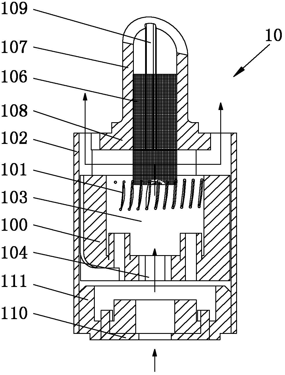
图1为本实用新型的可更换的通用雾化头的的剖面结构示意图;Fig. 1 is a schematic cross-sectional structure diagram of a replaceable universal atomizing head of the present invention;
图2为可更换的通用雾化头的立体图;Figure 2 is a perspective view of a replaceable universal atomizing head;
图3为在图1的基础上的增加了吸液部件之后的可更换的通用雾化头的的剖面结构图;Fig. 3 is a cross-sectional structure diagram of a replaceable universal atomizing head after adding a liquid suction part on the basis of Fig. 1;
图4为现有技术中雾化器的结构示意图;Fig. 4 is the structural representation of atomizer in the prior art;
附图中,10为通用雾化头,100为支撑座,101为加热装置,102为导电环,103为雾化腔,104为通气孔,105为吸液部件,106为导液绳,107为导液嘴,108为导液嘴座,109为导液槽,110为导电体,111为绝缘体。In the accompanying drawings, 10 is a universal atomizing head, 100 is a support seat, 101 is a heating device, 102 is a conductive ring, 103 is an atomization chamber, 104 is a vent hole, 105 is a liquid suction part, 106 is a liquid guide rope, 107 108 is a liquid guide seat, 109 is a liquid guide tank, 110 is a conductor, and 111 is an insulator.
具体实施方式 Detailed ways
下面结合附图和具体实施方式对本实用新型作进一步说明。Below in conjunction with accompanying drawing and specific embodiment, the utility model is further described.
参照图1至图3,本实用新型的通用雾化头10,该可通用雾化头10包括带有雾化腔的支撑座100、加热装置101、导电环102以及导液部件。支撑座100采用陶瓷制造而成,为了安装加热装置101,在支撑座100内设置了一个雾化腔103。为了使气体能够进入到雾化腔103中,在支撑座100的底部设置了一个通气孔104。加热装置101采用金属制成的电热丝,该加热装置101固定于支撑座100的雾化腔103中,加热装置的两端在装配成通用雾化头前均焊接上导线。导电环102一方面作为可通用雾化头的导电负极,另一方面用于装载其它零件。Referring to FIGS. 1 to 3 , the universal atomizing
参照图1,所述支撑座100固定在导电环102腔体的中部后将连接于加热装置一端的导线压紧在导电环和支撑座之间,使导线与导电环保持良好的接触,同时采用这样的方式无需人工以导电负极与加热装置进行焊接,可少减少一道工序,降低工人劳动强度。参照图3,为了能减少少许回流到通用雾化头上的雾化烟液对可更换的通用雾化头产生不良影响,在支撑座100的外表面包裹了一层吸液部件105,该吸液部件为镍网。在包裹了这个吸液部件后,将支撑座100安装到导电环102腔体的中部时,同样能使连接于加热装置一端的导线压紧在导电环和镍网之间,使导线与导电环保持良好的接触。Referring to Fig. 1, after the
参照图1至图3,所述导液部件包括导液绳106、导液嘴107以及与导液嘴连为一体的导液嘴座108。导液绳的一端位于导液液107中,导液绳106的另一端从导液嘴座108穿出后与加热装置连接,为了提高加热装置对烟液的加热效率,导液绳最好是缠绕在加热装置101的上部(从图上看),这样烟液流动的路径几乎是在整个加热装置,因此,以这种方式进行布置后,具有发热作用的加热装置101能提高对烟液的加热效率。虽然导液绳106帮助了流动到加热装置上的烟液的均匀性,由于导液绳的存在使烟液的流动速度变慢,于是在导液嘴107和导液嘴座108的内孔壁面上均设置了导液槽109,通过导液槽对烟液进行引流以提高烟液的流速,达到提供的烟液与加热装置加热时具有合适比例的目的,避免出现干烧的现象。导液嘴107和导液嘴座108实际上是一体成型的,因此导液嘴107和导液嘴座108上的导液槽109是一条连通的槽。导液槽109的数量与加热装置的布置方式有关,当导液嘴和导液嘴座上的导液槽109均为一个时,则加热装置101装配在支撑座的雾化腔中后其两端在同一水平线上,采用这种方式的理由在于:当加热装置101在同一水平线上时,烟液沿加热装置表面流动的路径短,因此,加热时雾化的速度快,如果烟液过多则会出现漏液的情况,因此,只需一个导液槽即可满足要求,采用一个导液槽的可更换的通用雾化头适合于少量吸取电子烟的人士。如果导液嘴和导液嘴座上的导液槽均为两个或三个,则加热装置101需以一端高另一端低的状态布置在支撑座的雾化腔中,即加热装置在支撑座100的雾化腔中以倾斜的状态布置,采用这种方式的理由在于:由于加热装置在支撑座100的雾化腔中以倾斜的状态布置,延长了烟液的流动路径,因而不会出现漏液的情况,因此,通过增加导液槽的数量来增加烟液的提供量,使烟雾量也得到提高。采用两个以上导液槽的通用雾化头适合于大量吸取电子烟的人士。由于本实用新型的通用雾化头具有可换性,因此同一人根据烟雾量的需求可以选择具体槽数的通用雾化头,对于使用者来说是相当地方便。导液嘴座108的一端插入到导电环102腔体的一端,导液嘴座108是外表呈圆柱形,在导液嘴座108的外圆周上沿其轴向截去一块截面体,这样,将导液嘴座108安装到导电环102中以后,导液嘴座108与导电环102之间就出现一个通道,这个通道是供烟液雾化后形成的烟雾通过的。Referring to FIGS. 1 to 3 , the liquid guiding component includes a
参照图1至图3,在导电环102腔体的另一端设有导电部件,该导电部件包括导电体110和绝缘体111。导电体110为通用雾化头的正极,导电体与连接于加热装置另一端的导线焊接,导电体110固定在绝缘体111上,导电体110为环形状,导电体110安装在绝缘体的轴向端面上设置的环形装配槽中。绝缘体紧固在导电环的腔体中,绝缘体上设有通气孔,该通气孔是供吸烟时负压气流通过的。将导电部件布置在导电环腔体另一端,增加了结构的紧凑性,减少了零件的使用,方便了安装。Referring to FIGS. 1 to 3 , a conductive component is provided at the other end of the cavity of the
Claims (4)
Priority Applications (1)
| Application Number | Priority Date | Filing Date | Title |
|---|---|---|---|
| CN2011203775456U CN202276830U (en) | 2011-09-28 | 2011-09-28 | Replaceable universal atomization head |
Applications Claiming Priority (1)
| Application Number | Priority Date | Filing Date | Title |
|---|---|---|---|
| CN2011203775456U CN202276830U (en) | 2011-09-28 | 2011-09-28 | Replaceable universal atomization head |
Publications (1)
| Publication Number | Publication Date |
|---|---|
| CN202276830U true CN202276830U (en) | 2012-06-20 |
Family
ID=46223018
Family Applications (1)
| Application Number | Title | Priority Date | Filing Date |
|---|---|---|---|
| CN2011203775456U Expired - Lifetime CN202276830U (en) | 2011-09-28 | 2011-09-28 | Replaceable universal atomization head |
Country Status (1)
| Country | Link |
|---|---|
| CN (1) | CN202276830U (en) |
Cited By (4)
| Publication number | Priority date | Publication date | Assignee | Title |
|---|---|---|---|---|
| CN102389167A (en) * | 2011-09-28 | 2012-03-28 | 卓尔悦(常州)电子科技有限公司 | Replaceable general atomizing head |
| WO2014205749A1 (en) * | 2013-06-27 | 2014-12-31 | 瑞吉高新科技股份有限公司 | Electronic cigarette vaporizer and electronic cigarette |
| CN104397880A (en) * | 2014-12-01 | 2015-03-11 | 深圳佳品健怡科技有限公司 | Electronic cigarette |
| WO2015109476A1 (en) * | 2014-01-23 | 2015-07-30 | 深圳市康尔科技有限公司 | Heating assembly of electronic cigarette, and atomizing structure |
-
2011
- 2011-09-28 CN CN2011203775456U patent/CN202276830U/en not_active Expired - Lifetime
Cited By (6)
| Publication number | Priority date | Publication date | Assignee | Title |
|---|---|---|---|---|
| CN102389167A (en) * | 2011-09-28 | 2012-03-28 | 卓尔悦(常州)电子科技有限公司 | Replaceable general atomizing head |
| CN102389167B (en) * | 2011-09-28 | 2013-05-29 | 卓尔悦(常州)电子科技有限公司 | Replaceable general atomizing head |
| WO2014205749A1 (en) * | 2013-06-27 | 2014-12-31 | 瑞吉高新科技股份有限公司 | Electronic cigarette vaporizer and electronic cigarette |
| WO2015109476A1 (en) * | 2014-01-23 | 2015-07-30 | 深圳市康尔科技有限公司 | Heating assembly of electronic cigarette, and atomizing structure |
| CN104397880A (en) * | 2014-12-01 | 2015-03-11 | 深圳佳品健怡科技有限公司 | Electronic cigarette |
| CN104397880B (en) * | 2014-12-01 | 2017-05-10 | 延吉长白山科技服务有限公司 | Electronic cigarette |
Similar Documents
| Publication | Publication Date | Title |
|---|---|---|
| CN102389167B (en) | Replaceable general atomizing head | |
| CN203555161U (en) | Atomizer and electronic cigarette provided therewith | |
| CN206808660U (en) | Electronic cigarette | |
| CN207784269U (en) | Atomization components and electronic cigarettes | |
| CN203851804U (en) | Atomization device of electronic cigarette and electronic cigarette | |
| CN202286308U (en) | Atomization head-replaceable atomizer | |
| CN103960780B (en) | Tobacco tar atomising device and electronic cigarette | |
| CN213604377U (en) | an electronic cigarette | |
| CN203446525U (en) | Atomization device of electronic cigarette and electronic cigarette | |
| US20140196718A1 (en) | Disposable electronic cigarette | |
| CN111466614A (en) | Atomizing core, atomizer and electronic atomization device | |
| CN109892697B (en) | Ultrasonic electronic cigarette atomization core and atomizer | |
| WO2016123781A1 (en) | Atomisation assembly and electronic cigarette | |
| CN206079033U (en) | Low temperature cigarette | |
| CN106235416B (en) | Atomizer for electronic cigarette and electronic cigarette | |
| CN202276830U (en) | Replaceable universal atomization head | |
| CN204670379U (en) | Atomizer and electronic cigarette | |
| CN204146321U (en) | Atomizer and there is the electronic cigarette of this atomizer | |
| CN206603244U (en) | A kind of electronic smoke atomizer and electronic cigarette | |
| CN106235412A (en) | Replaceable core and replaceable oil cup atomizer | |
| CN204540841U (en) | Atomizer and electronic cigarette | |
| CN206251933U (en) | Electronic smoke atomizer with gradually expanded form pipe | |
| CN205848695U (en) | an electronic cigarette | |
| CN206547878U (en) | Atomizing head, atomizer and electron cigarette thereof | |
| CN211510572U (en) | A kind of atomizer and its heating component |
Legal Events
| Date | Code | Title | Description |
|---|---|---|---|
| C14 | Grant of patent or utility model | ||
| GR01 | Patent grant | ||
| CP03 | Change of name, title or address | ||
| CP03 | Change of name, title or address |
Address after: 213125 Jiangsu city of Changzhou province Xue Fengxiang Road 7 North, Room 401 Patentee after: Jiangsu Juwei Electronic Technology Co.,Ltd. Address before: 213022 Jiangsu city of Changzhou province Taihu New District No. 8 East Road, No. 2 building, 607 floor, Fu Chen Patentee before: JOYETECH (CHANGZHOU) ELECTRONICS Co.,Ltd. |
|
| TR01 | Transfer of patent right | ||
| TR01 | Transfer of patent right |
Effective date of registration: 20170307 Address after: Zug city - Genieer ghuysen - Street No. 6 Patentee after: JOYETECH EUROPE HOLDING GmbH Address before: 213125 Jiangsu city of Changzhou province Xue Fengxiang Road 7 North, Room 401 Patentee before: Jiangsu Juwei Electronic Technology Co.,Ltd. |
|
| CX01 | Expiry of patent term | ||
| CX01 | Expiry of patent term |
Granted publication date: 20120620 |