CN202425172U - T8 to T5 lamp electronic ballast - Google Patents
T8 to T5 lamp electronic ballast Download PDFInfo
- Publication number
- CN202425172U CN202425172U CN2011203879614U CN201120387961U CN202425172U CN 202425172 U CN202425172 U CN 202425172U CN 2011203879614 U CN2011203879614 U CN 2011203879614U CN 201120387961 U CN201120387961 U CN 201120387961U CN 202425172 U CN202425172 U CN 202425172U
- Authority
- CN
- China
- Prior art keywords
- circuit
- fluorescent tube
- bridge inversion
- electric ballast
- power supply
- Prior art date
- Legal status (The legal status is an assumption and is not a legal conclusion. Google has not performed a legal analysis and makes no representation as to the accuracy of the status listed.)
- Expired - Fee Related
Links
- 238000001914 filtration Methods 0.000 claims description 10
- 238000006243 chemical reaction Methods 0.000 claims description 9
- 239000003990 capacitor Substances 0.000 claims description 6
- 230000006698 induction Effects 0.000 claims description 6
- 230000008878 coupling Effects 0.000 claims description 3
- 238000010168 coupling process Methods 0.000 claims description 3
- 238000005859 coupling reaction Methods 0.000 claims description 3
- 230000002093 peripheral effect Effects 0.000 claims description 3
- 238000004804 winding Methods 0.000 description 4
- 230000007812 deficiency Effects 0.000 description 2
- 238000010923 batch production Methods 0.000 description 1
- 230000007547 defect Effects 0.000 description 1
- 238000010586 diagram Methods 0.000 description 1
- 230000000694 effects Effects 0.000 description 1
- 238000005516 engineering process Methods 0.000 description 1
- 230000001939 inductive effect Effects 0.000 description 1
- 238000012797 qualification Methods 0.000 description 1
- 230000001105 regulatory effect Effects 0.000 description 1
- 230000009466 transformation Effects 0.000 description 1
Images

Landscapes
- Circuit Arrangements For Discharge Lamps (AREA)
Abstract
The utility model discloses a T8 to T5 lamp electronic ballast, comprising a rectification filter circuit, a half-bridge inversion circuit, a filament power supply circuit and a lamp tube. The rectification filter circuit is connected to the half-bridge inversion circuit, DC is converted to AC output by the half-bridge inversion, and the filament power supply circuit is connected to the half-bridge inversion circuit. According to the utility model, the circuit is simple, reliability is high, the volume is small, the cost is low, the luminous efficiency is high, the structure is simple, the production efficiency in batches is greatly raised, and the application popularization of the T8 to T5 lamp electronic ballast is promoted.
Description
Technical field
The utility model relates to technical field of lighting fixtures, particularly a kind of electric ballast of T8 conversion T5 fluorescent tube.
Background technology
The output of electric ballast commonly used all is through the LC resonant network, produces high-frequency and high-voltage, lights fluorescent tube.That is to say that the output of electric ballast wants 4 lines to be connected with fluorescent tube.
But the use occasion that some is specific by above-mentioned wiring, will cause tangible deficiency.Example: the T5 sleeve pipe product of replacement T8, by conventional usage, will adopt 3-4 bar connecting line at least at the two ends of fluorescent tube, about 1200 centimetres of length.For the connecting line that makes fluorescent tube is not messy, will increase an annex that is used for hidden connecting line, about 1200 millimeters of length, the about 10-15 millimeter of width simultaneously.
Because the existence of connecting line and accessory kit causes this type of product structure complicacy, cost is high, the low obviously deficiency that waits of light efficiency.
Therefore, how to simplify the circuit of electric ballast, reduce its cost, improve light efficiency, simplify the operation of producing in batches, improving the efficient of producing in batches is the technical problem that needs to be resolved hurrily in the industry.
Summary of the invention
It is simple that the main purpose of the utility model provides a kind of circuit, and reliability is high, and volume is little, and cost is low, the electric ballast of T8 conversion T5 fluorescent tube easy to use, and it is complicated to be intended to overcome circuit of electronic ballast of the prior art, and volume is big, defect of high cost.
The utility model proposes a kind of electric ballast of T8 conversion T5 fluorescent tube; Comprise current rectifying and wave filtering circuit, half-bridge inversion circuit, filament power supply circuits and fluorescent tube; It is characterized in that: said current rectifying and wave filtering circuit connects half-bridge inversion circuit, and semi-bridge inversion is converted into alternating current output with direct current; What be connected with half-bridge inversion circuit is the filament power supply circuits.
Preferably, said current rectifying and wave filtering circuit comprises bridge rectifier BR that four diodes are formed and the filter capacitor C1 that is connected the bridge rectifier output.
Preferably, said half-bridge inversion circuit is by transistor Q1, Q2, and pulse transformer T1 and peripheral cell are formed.
Preferably, said pulse transformer T1 is made up of primary coil L1, L2 and secondary coil L3.
Preferably, the coupling circuit formed by choke induction T2 and capacitor C 5, C6, C7 of said filament power supply circuits.The inductance value of said choke induction T2 and secondary winding are adjustable.
The utility model has the advantages that: circuit is simple, and reliability is high, and volume is little, and cost is low, can increase substantially the efficient of batch process.
Description of drawings
Fig. 1 is the structural representation of the utility model one embodiment;
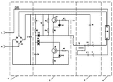
Fig. 2 is the circuit theory diagrams of the utility model one embodiment.
The realization of the utility model purpose, functional characteristics and advantage will combine embodiment, further specify with reference to accompanying drawing.
Embodiment
Should be appreciated that specific embodiment described herein only in order to explanation the utility model, and be not used in qualification the utility model.
With reference to Fig. 1, Fig. 2, an embodiment of the utility model electric ballast comprises current rectifying and wave filtering circuit 1; Half-bridge inversion circuit 2; Filament power supply circuits 3 and fluorescent tube 4, said current rectifying and wave filtering circuit 1 connects half-bridge inversion circuit 2, and half-bridge inversion circuit 2 is converted into alternating current output with direct current; What be connected with half-bridge inversion circuit 2 is filament power supply circuits 3.
Wherein, Said current rectifying and wave filtering circuit comprises bridge rectifier BR that four diodes are formed and the filter capacitor C1 that is connected the bridge rectifier output.Said half-bridge inversion circuit is by transistor Q1, Q2, and pulse transformer T1 and peripheral cell are formed.Said pulse transformer T1 is made up of primary coil L1, L2 and secondary coil L3.The coupling circuit that said filament power supply circuits 3 are made up of choke induction T2 and capacitor C 5, C6, C7.The inductance value of said choke induction T2 and secondary winding are adjustable.
When circuit connects energising by Fig. 2, a branch road is through an insurance and an end filament, is added to the input of electric ballast simultaneously with another road, after BR rectification and C1 filtering, obtains the direct voltage of about 300V.The electric current that provides of voltage charges to C2 through R1, R2 thus, when its voltage reaches the breakover voltage of DB, and the DB conducting, and have electric current to inject the base stage of Q2, make the Q2 conducting.Because the effect of pulse transformer T1, Q1, Q2 take turns conducting, and electric ballast produces high frequency voltage and with electric current the T5 fluorescent lamp supplied power, and lights the T5 fluorescent tube.
The preheating of filament and power supply: an end filament is through alternating current (or after being connected on Inductive ballast), and its heater current is exactly the operating current of electric ballast, reasonably regulates this current value, makes filament be in good working order.Other end filament is by producing a high frequency low voltage electric current on the auxiliary winding of the choke induction in the ballast; The electric capacity of reasonably regulating the number of turn on the auxiliary winding and connecting with it; Scalable is added in the voltage and current on this segment filament, to filament a good working order is provided.
The above is merely the preferred embodiment of the utility model; Be not thus the restriction the utility model claim; Every equivalent structure transformation that utilizes the utility model specification and accompanying drawing content to be done; Or directly or indirectly be used in other relevant technical fields, all in like manner be included in the scope of patent protection of the utility model.
Claims (5)
1. the electric ballast of T8 conversion T5 fluorescent tube; Comprise current rectifying and wave filtering circuit, half-bridge inversion circuit, filament power supply circuits and fluorescent tube; It is characterized in that: said current rectifying and wave filtering circuit connects half-bridge inversion circuit, and half-bridge inversion circuit is converted into alternating current output with direct current; What be connected with half-bridge inversion circuit is the filament power supply circuits.
2. the electric ballast of T8 conversion T5 fluorescent tube according to claim 1 is characterized in that said current rectifying and wave filtering circuit comprises bridge rectifier BR that four diodes are formed and the filter capacitor C1 that is connected the bridge rectifier output.
3. the electric ballast of T8 conversion T5 fluorescent tube according to claim 2 is characterized in that said half-bridge inversion circuit is made up of transistor Q1, Q2, pulse transformer T1 and peripheral cell.
4. the electric ballast of T8 conversion T5 fluorescent tube according to claim 3 is characterized in that said pulse transformer T1 is made up of primary coil L1, L2 and secondary coil L3.
5. the electric ballast of T8 conversion T5 fluorescent tube according to claim 2 is characterized in that the coupling circuit that said filament power supply circuits are made up of choke induction T2 and capacitor C 5, C6, C7.
Priority Applications (1)
| Application Number | Priority Date | Filing Date | Title |
|---|---|---|---|
| CN2011203879614U CN202425172U (en) | 2011-10-13 | 2011-10-13 | T8 to T5 lamp electronic ballast |
Applications Claiming Priority (1)
| Application Number | Priority Date | Filing Date | Title |
|---|---|---|---|
| CN2011203879614U CN202425172U (en) | 2011-10-13 | 2011-10-13 | T8 to T5 lamp electronic ballast |
Publications (1)
| Publication Number | Publication Date |
|---|---|
| CN202425172U true CN202425172U (en) | 2012-09-05 |
Family
ID=46749891
Family Applications (1)
| Application Number | Title | Priority Date | Filing Date |
|---|---|---|---|
| CN2011203879614U Expired - Fee Related CN202425172U (en) | 2011-10-13 | 2011-10-13 | T8 to T5 lamp electronic ballast |
Country Status (1)
| Country | Link |
|---|---|
| CN (1) | CN202425172U (en) |
-
2011
- 2011-10-13 CN CN2011203879614U patent/CN202425172U/en not_active Expired - Fee Related
Similar Documents
| Publication | Publication Date | Title |
|---|---|---|
| CN102155642B (en) | LED (light emitting diode) daylight lamp and connecting circuit thereof | |
| CN102155644B (en) | LED (light emitting diode) fluorescent lamp and fluorescent lamp connecting circuit | |
| WO2013026267A1 (en) | Self-excited push-pull converter | |
| US8723433B2 (en) | Power transformation apparatus between DC light element and ballast | |
| CN202425172U (en) | T8 to T5 lamp electronic ballast | |
| CN101321423B (en) | Road lamp electric ballast | |
| CN108521694A (en) | A LED half-bridge circuit with feedback variable frequency constant current drive | |
| CN203872421U (en) | DC 12V-48V wide-voltage large-power electrodeless lamp ballast | |
| CN102155646A (en) | Light-emitting diode (LED) fluorescent lamp and connecting circuit thereof | |
| CN202841669U (en) | A New Ballast Circuit for Electrodeless Lamp | |
| CN102155643B (en) | LED (Light Emitting Diode) fluorescent lamp and fluorescent lamp connecting circuit | |
| CN103220836B (en) | The supporting LED universal lamp tube of ballast | |
| CN201541385U (en) | Dimmable induction lamp | |
| CN202127539U (en) | Energy-saving recycling ballast | |
| CN201114920Y (en) | Multi-tube high-efficiency electronic ballast | |
| CN201557312U (en) | A new type of high-efficiency and long-life fluorescent lamp electronic ballast circuit | |
| CN105472832A (en) | Led lamp | |
| CN202697008U (en) | Integrated magnetics transformer for high frequency high voltage sodium lamp electronic ballast, and ballast | |
| CN203708556U (en) | LED driving circuit and LED fluorescent lamp using the driving circuit | |
| CN203181383U (en) | Ballast circuit | |
| CN102155645A (en) | LED (light emitting diode) fluorescent lamp and fluorescent lamp connecting circuit | |
| CN102155648A (en) | LED (light-emitting diode) fluorescent lamp and fluorescent lamp connecting circuit | |
| CN210225814U (en) | Multi-lamp electronic ballast | |
| CN102378458A (en) | High-power fluorescent lamp ballast | |
| CN205430670U (en) | Compatible type keeps apart NOT AND and keeps apart emitting diode power |
Legal Events
| Date | Code | Title | Description |
|---|---|---|---|
| C14 | Grant of patent or utility model | ||
| GR01 | Patent grant | ||
| C17 | Cessation of patent right | ||
| CF01 | Termination of patent right due to non-payment of annual fee |
Granted publication date: 20120905 Termination date: 20131013 |