CN202493616U - Brake callipers for structure-improved brake pad gap filling pieces - Google Patents
Brake callipers for structure-improved brake pad gap filling pieces Download PDFInfo
- Publication number
- CN202493616U CN202493616U CN2012200944974U CN201220094497U CN202493616U CN 202493616 U CN202493616 U CN 202493616U CN 2012200944974 U CN2012200944974 U CN 2012200944974U CN 201220094497 U CN201220094497 U CN 201220094497U CN 202493616 U CN202493616 U CN 202493616U
- Authority
- CN
- China
- Prior art keywords
- brake pad
- shim
- brake
- caliper
- improved structure
- Prior art date
- Legal status (The legal status is an assumption and is not a legal conclusion. Google has not performed a legal analysis and makes no representation as to the accuracy of the status listed.)
- Expired - Lifetime
Links
Images


Landscapes
- Braking Arrangements (AREA)
Abstract
本实用新型公开了一种刹车片填隙片结构改进的制动卡钳,包括刹车片总成;该刹车片总成包括刹车片和填隙片;刹车片和填隙片呈叠合相配合;在刹车片和填隙片相叠合时,该填隙片的一端具有与刹车片的一端吻合对应的形状,该填隙片的另一端配合在刹车片的中部位置,且该填隙片的另一端端沿呈弧形形状。采用该结构后,可以在制动过程中有效地改变刹车片的振动频率,有效地避免由于制动频率相近导致的异响产生,从而提高了驾驶的舒适性。
The utility model discloses a brake caliper with an improved structure of a brake pad gap filler, which comprises a brake pad assembly; the brake pad assembly includes a brake pad and a gap filler; the brake pad and the gap filler are superimposed and matched; When the brake pad and the shim are stacked, one end of the shim has a shape corresponding to one end of the brake pad, the other end of the shim is fitted in the middle of the brake pad, and the end of the shim is The other end edge is arc-shaped. After adopting this structure, the vibration frequency of the brake pad can be effectively changed during the braking process, and abnormal noise caused by similar braking frequencies can be effectively avoided, thereby improving driving comfort.
Description
技术领域 technical field
本实用新型涉及一种汽车车轮的制动卡钳,特别是涉及一种刹车片填隙片结构改进的制动卡钳。The utility model relates to a brake caliper for an automobile wheel, in particular to a brake caliper with an improved structure of a brake disc filler.
背景技术 Background technique
现有的汽车车轮通常采用盘式自动器进行制动。盘式制动器又称为碟式制动器,它由液压控制,主要零部件有制动盘、分泵、制动卡钳、油管等。制动卡钳包括有固定架、缸体、活塞、内刹车片总成和外刹车片组件,缸体安装在固定架中并可相对于固定架移动,活塞配合在缸体内并可相对于缸体移动,活塞的内端配合在缸体内,活塞的外端与内刹车片总成相固定,缸体被设计成卡口形结构,卡口的一侧设置有缸套,活塞就是配合在该缸套中,卡口的另一侧固定外刹车片组件。当驾驶员踩踏刹车板时,缸体的缸套的油腔产生油压,并推动活塞向外侧移动,活塞的外端与内刹车片总成联接在一起,活塞的向缸套外侧移动也就推动内刹车片总成压向制动盘,与此同时,缸体的缸套的油腔所产生油压也沿着活塞运动相反方向施加,受油压的推动,缸体沿活塞运动相反方向移动,使缸体的卡口的另一侧所固定的外刹车片组件也压向制动盘,形成对制动盘的制动效果。图1为现有技术的制动卡钳的刹车片总成的结构示意图,图2为现有技术的制动卡钳的刹车片总成的侧视图,该刹车片总成包括填隙片1′,该填隙片1′的周边形状与刹车片的周边形状相吻合,由于卡钳在制动过程中与车辆同时振动,当卡钳的振动频率与车辆碟盘及转向节相近时,卡钳容易发生共振并最终造成异响,影响驾车的舒适度。Existing automobile wheels are usually braked with disc automatics. Disc brakes, also known as disc brakes, are controlled by hydraulic pressure, and the main components include brake discs, cylinders, brake calipers, oil pipes, etc. The brake caliper includes a fixed frame, a cylinder body, a piston, an inner brake pad assembly and an outer brake pad assembly. The cylinder body is installed in the fixed frame and can move relative to the fixed frame. The piston fits in the cylinder body and can move relative to the cylinder The body moves, the inner end of the piston fits in the cylinder body, the outer end of the piston is fixed with the inner brake pad assembly, the cylinder body is designed as a bayonet-shaped structure, and a cylinder liner is arranged on one side of the bayonet, and the piston fits in the In the cylinder liner, the other side of the bayonet is fixed to the outer brake pad assembly. When the driver steps on the brake pedal, the oil chamber of the cylinder liner of the cylinder body generates oil pressure and pushes the piston to move outward. The outer end of the piston is connected with the inner brake pad assembly, and the piston moves to the outside of the cylinder liner. Push the inner brake pad assembly to press the brake disc. At the same time, the oil pressure generated by the oil chamber of the cylinder liner of the cylinder is also applied in the opposite direction of the piston movement. Pushed by the oil pressure, the cylinder moves in the opposite direction of the piston movement. Moving, the outer brake pad assembly fixed on the other side of the bayonet of the cylinder body is also pressed against the brake disc to form a braking effect on the brake disc. Fig. 1 is a schematic structural view of a brake pad assembly of a brake caliper in the prior art, and Fig. 2 is a side view of a brake pad assembly of a brake caliper in the prior art, the brake pad assembly includes a shim 1', The peripheral shape of the spacer 1' coincides with the peripheral shape of the brake pad. Since the caliper vibrates simultaneously with the vehicle during braking, when the vibration frequency of the caliper is similar to that of the vehicle disc and steering knuckle, the caliper is prone to resonance and Ultimately, abnormal noise is caused, which affects the comfort of driving.
实用新型内容 Utility model content
本实用新型的目的在于克服现有技术之不足,提供一种刹车片填隙片结构改进的制动卡钳,通过对刹车片填隙片结构进行改进,可以在制动过程中有效地改变刹车片的振动频率,有效地避免由于制动频率相近导致的异响产生,从而提高了驾驶的舒适性。The purpose of the utility model is to overcome the deficiencies of the prior art and provide a brake caliper with an improved structure of the brake pad gap filler. By improving the structure of the brake pad gap filler, the brake pad can be effectively changed during the braking process. The vibration frequency can effectively avoid the abnormal noise caused by the similar braking frequency, thus improving the driving comfort.
本实用新型解决其技术问题所采用的技术方案是:一种刹车片填隙片结构改进的制动卡钳,包括刹车片总成;该刹车片总成包括刹车片和填隙片;刹车片和填隙片呈叠合相配合;在刹车片和填隙片相叠合时,该填隙片的一端具有与刹车片的一端吻合对应的形状,该填隙片的另一端配合在刹车片的中部位置,且该填隙片的另一端端沿呈弧形形状。The technical solution adopted by the utility model to solve the technical problem is: a brake caliper with an improved structure of the brake pad filler, including a brake pad assembly; the brake pad assembly includes a brake pad and a gap filler; the brake pad and The shims are stacked and matched; when the brake pads and the shims are stacked, one end of the shim has a shape corresponding to one end of the brake pad, and the other end of the shim is fitted on the brake pad. The middle position, and the other end of the spacer is arc-shaped.
所述的填隙片的另一端端沿呈半圆弧形状。The other end edge of the spacer is in the shape of a semicircle.
所述的填隙片的另一端端沿呈半椭圆形状。The other end edge of the said spacer is in the shape of a semi-ellipse.
所述的填隙片的另一端端沿设在对应于刹车片的中部且偏向刹车片的另一端的位置。The other end of the spacer is arranged at a position corresponding to the middle of the brake pad and biased toward the other end of the brake pad.
所述的填隙片的另一端端沿设在对应于刹车片的中部至刹车片的另一端之间的中间位置。The other end of the spacer is arranged at a middle position corresponding to the middle of the brake pad to the other end of the brake pad.
所述的填隙片为不锈钢填隙片。The shims are stainless steel shims.
本实用新型的一种刹车片填隙片结构改进的制动卡钳,是对刹车片填隙片结构进行改进,让填隙片的另一端端沿并不与刹车片的另一端吻合对应,而是形成不规则形状,且填隙片与刹车片相贴合的面积要小于刹车片,可以在制动过程中有效地改变刹车片的振动频率。The utility model relates to a brake caliper with an improved structure of the brake pad shim, which improves the structure of the brake pad shim so that the edge of the other end of the brake pad does not correspond to the other end of the brake pad. It forms an irregular shape, and the area where the spacer and the brake pad fit together is smaller than the brake pad, which can effectively change the vibration frequency of the brake pad during the braking process.
本实用新型的有益效果是:由于采用了在刹车片和填隙片相叠合时,该填隙片被设计成,其一端具有与刹车片的一端吻合对应的形状,其另一端则配合在刹车片的中部位置,且该填隙片的另一端端沿呈弧形形状。这种结构,使得填隙片的另一端相对于刹车片的另一端成不相配合形状,可以在制动过程中有效地改变刹车片的振动频率,有效地避免由于制动频率相近导致的异响产生,从而提高了驾驶的舒适性。The beneficial effect of the utility model is that: when the brake pad and the shim are superimposed, the shim is designed such that one end thereof has a shape corresponding to one end of the brake pad, and the other end fits in the The middle position of the brake pad, and the other end of the spacer is arc-shaped. With this structure, the other end of the spacer is in a non-fitting shape relative to the other end of the brake pad, which can effectively change the vibration frequency of the brake pad during the braking process and effectively avoid abnormal vibrations caused by similar braking frequencies. Noise is generated, thereby improving driving comfort.
以下结合附图及实施例对本实用新型作进一步详细说明;但本实用新型的一种刹车片填隙片结构改进的制动卡钳不局限于实施例。The utility model will be described in further detail below in conjunction with the accompanying drawings and embodiments; however, the brake caliper with improved structure of the brake pad shim of the utility model is not limited to the embodiments.
附图说明Description of drawings
图1是现有技术的制动卡钳的刹车片总成的结构示意图;Fig. 1 is a structural schematic diagram of a brake pad assembly of a brake caliper in the prior art;
图2是本实用新型的制动卡钳的构造示意图;Fig. 2 is a structural schematic diagram of the brake caliper of the present utility model;
图3是图2所示的制动卡钳前后翻转180度的结构示意图;Fig. 3 is a structural schematic diagram of the brake caliper shown in Fig. 2 flipped forward and backward by 180 degrees;
图4是沿图3中A-A线的剖视图;Fig. 4 is a sectional view along line A-A in Fig. 3;
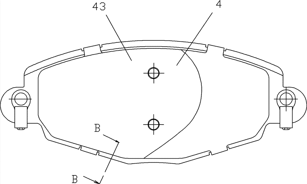
图5是本实用新型的制动卡钳的刹车片总成的构造示意图;Fig. 5 is a structural schematic diagram of the brake pad assembly of the brake caliper of the present invention;
图6是沿图5中B-B线的剖视图;Fig. 6 is a sectional view along the line B-B in Fig. 5;
图7是本实用新型的制动卡钳的刹车片总成的填隙片的构造示意图。Fig. 7 is a schematic structural view of the shims of the brake pad assembly of the brake caliper of the present invention.
具体实施方式 Detailed ways
实施例,参见图2至图4所示,本实用新型的一种刹车片填隙片结构改进的制动卡钳,包括有固定架1、缸体2、活塞3、内刹车片总成4和外刹车片组件5,缸体2安装在固定架1中并可相对于固定架1移动,活塞3配合在缸体2内并可相对于缸体2移动,活塞3的内端配合在缸体2内,活塞3的外端与内刹车片总成4相固定,缸体2被设计成卡口形结构,卡口的一侧设置有缸套,活塞就是配合在该缸套中,卡口的另一侧固定外刹车片组件5。Embodiment, referring to Fig. 2 to Fig. 4, a brake caliper with an improved structure of the brake pad shim of the present utility model includes a
外刹车片组件5主要由刹车片和橡胶填隙片组成。The outer brake pad assembly 5 is mainly made up of brake pads and rubber shims.
参见图5至图7所示,内刹车片总成4则主要由刹车片、二硫化钼、橡胶填隙片41、3M胶42、不锈钢填隙片43等组成。5 to 7, the inner
刹车片和不锈钢填隙片43呈叠合相配合;在刹车片和不锈钢填隙片43相叠合时,该不锈钢填隙片43的一端具有与刹车片的一端吻合对应的形状,该不锈钢填隙片43的另一端配合在刹车片的中部位置,且该不锈钢填隙片43的另一端端沿呈弧形形状。The brake pad and the
所述的不锈钢填隙片43的另一端端沿431呈半圆弧形状。当然,所述的不锈钢填隙片的另一端端沿也可以呈半椭圆形状。The other end of the
所述的不锈钢填隙片43的另一端端沿431设在对应于刹车片的中部且偏向刹车片的另一端的位置。当然,所述的不锈钢填隙片43的另一端端沿也可以设在对应于刹车片的中部至刹车片的另一端之间的中间位置。The other end edge 431 of the
本实用新型的一种刹车片填隙片结构改进的制动卡钳,是对刹车片填隙片结构进行改进,让不锈钢填隙片43的另一端端沿431并不与刹车片的另一端吻合对应,而是形成不规则形状,且不锈钢填隙片43与刹车片相贴合的面积要小于刹车片,可以在制动过程中有效地改变刹车片的振动频率。A brake caliper with an improved structure of the brake pad filler of the utility model is to improve the structure of the brake pad filler so that the other end edge 431 of the stainless
上述实施例仅用来进一步说明本实用新型的一种刹车片填隙片结构改进的制动卡钳,但本实用新型并不局限于实施例,凡是依据本实用新型的技术实质对以上实施例所作的任何简单修改、等同变化与修饰,均落入本实用新型技术方案的保护范围。The above-mentioned embodiments are only used to further illustrate a brake caliper with an improved structure of the brake pad shim of the present invention, but the present invention is not limited to the embodiments. Any simple modifications, equivalent changes and modifications all fall within the scope of protection of the technical solution of the utility model.
Claims (6)
Priority Applications (1)
| Application Number | Priority Date | Filing Date | Title |
|---|---|---|---|
| CN2012200944974U CN202493616U (en) | 2012-03-13 | 2012-03-13 | Brake callipers for structure-improved brake pad gap filling pieces |
Applications Claiming Priority (1)
| Application Number | Priority Date | Filing Date | Title |
|---|---|---|---|
| CN2012200944974U CN202493616U (en) | 2012-03-13 | 2012-03-13 | Brake callipers for structure-improved brake pad gap filling pieces |
Publications (1)
| Publication Number | Publication Date |
|---|---|
| CN202493616U true CN202493616U (en) | 2012-10-17 |
Family
ID=46999848
Family Applications (1)
| Application Number | Title | Priority Date | Filing Date |
|---|---|---|---|
| CN2012200944974U Expired - Lifetime CN202493616U (en) | 2012-03-13 | 2012-03-13 | Brake callipers for structure-improved brake pad gap filling pieces |
Country Status (1)
| Country | Link |
|---|---|
| CN (1) | CN202493616U (en) |
-
2012
- 2012-03-13 CN CN2012200944974U patent/CN202493616U/en not_active Expired - Lifetime
Similar Documents
| Publication | Publication Date | Title |
|---|---|---|
| CN203023344U (en) | Disc brake device | |
| CN102829107B (en) | A kind of disk type braker and a kind of braking system and a kind of motorcycle | |
| CN202493616U (en) | Brake callipers for structure-improved brake pad gap filling pieces | |
| CN206206449U (en) | A kind of brake block for reducing brake noise | |
| CN203685946U (en) | Feedback-type automobile disc brake | |
| KR101394126B1 (en) | Disk brake | |
| CN206734312U (en) | Stop mechanism and the rail vehicle with the stop mechanism | |
| KR20090043182A (en) | Caliper brake | |
| CN205446488U (en) | Disc brake and car | |
| CN203796813U (en) | Disc brake noise reduction spring and disc brake | |
| CN202413764U (en) | Brakes on sweepers | |
| CN104595384A (en) | Disk braking system for electric automobile axle assembly | |
| CN104214246B (en) | Single-cylinder double-action calipers | |
| TW201413130A (en) | Brake backing plate with step-chamfer | |
| CN204845902U (en) | Security car | |
| CN207843199U (en) | Disc brake apparatus after a kind of motorcycle bottom fork | |
| KR20090043207A (en) | Car Disc Brake | |
| CN205371375U (en) | A drum brake for car braking | |
| CN202418347U (en) | Brake caliper with improved yoke spring structure | |
| CN201858285U (en) | Disc brake with bearable connecting plate | |
| CN205383206U (en) | Braking piece assembly with fixed spring | |
| KR101571669B1 (en) | Brake drum having different materials and method for manufacturing the same | |
| CN204493503U (en) | Drum brake for rear axle of lorry floor pan assembly | |
| KR20120029918A (en) | Brake apparatus for vehicle | |
| CN210769927U (en) | A multifunctional and universal protective cover for automobile brake calipers |
Legal Events
| Date | Code | Title | Description |
|---|---|---|---|
| C14 | Grant of patent or utility model | ||
| GR01 | Patent grant | ||
| CX01 | Expiry of patent term |
Granted publication date: 20121017 |
|
| CX01 | Expiry of patent term |