CN202494821U - Porous adjustable inlet wire sealing device for cable connector box - Google Patents
Porous adjustable inlet wire sealing device for cable connector box Download PDFInfo
- Publication number
- CN202494821U CN202494821U CN2012201067804U CN201220106780U CN202494821U CN 202494821 U CN202494821 U CN 202494821U CN 2012201067804 U CN2012201067804 U CN 2012201067804U CN 201220106780 U CN201220106780 U CN 201220106780U CN 202494821 U CN202494821 U CN 202494821U
- Authority
- CN
- China
- Prior art keywords
- inlet wire
- cable
- porous
- packoff
- adjustable inlet
- Prior art date
- Legal status (The legal status is an assumption and is not a legal conclusion. Google has not performed a legal analysis and makes no representation as to the accuracy of the status listed.)
- Expired - Lifetime
Links
- 238000007789 sealing Methods 0.000 claims abstract description 18
- 230000000694 effects Effects 0.000 abstract description 2
- 230000035515 penetration Effects 0.000 abstract 2
- 230000009286 beneficial effect Effects 0.000 description 1
- 238000004891 communication Methods 0.000 description 1
- 238000005516 engineering process Methods 0.000 description 1
- 230000007613 environmental effect Effects 0.000 description 1
- 239000012467 final product Substances 0.000 description 1
- 230000003287 optical effect Effects 0.000 description 1
- 238000004064 recycling Methods 0.000 description 1
- 239000002699 waste material Substances 0.000 description 1
Images


Landscapes
- Cable Accessories (AREA)
Abstract
The utility model discloses a porous adjustable inlet wire sealing device for a cable connector box. The device comprises a cylindrical body. A side of the body is provided with a plurality of annular grooves, and the annular grooves are matched with projections of corresponding positions of the cable connector box such that the porous adjustable inlet wire sealing device can be clamped on the cable connector box. Two end faces of the body are provided with a plurality of inlet wire ports which are along an axial direction and are used for penetration of cables. Each of the inlet wire ports is provided with a conical cap which seals an inlet wire port. When in use, according to a size of a cable diameter, openings are cut at different positions of the conical cap for penetration of the cables. The porous adjustable inlet wire sealing device is installed on the cable connector box through the annular grooves on the device. The porous adjustable inlet wire sealing device is provided with a plurality of holes, connection of a plurality of cables can be realized, a sealing effect is good, and reutilization is available.
Description
Technical field
The utility model relates to a kind of cable splice closure, relates in particular to a kind of cable splice closure with the adjustable inlet wire packoff of porous, belongs to the optical communication equipment technical field.
Background technology
Sealing joint strip is adopted in the sealing of cable splice closure at present more, during the cable inlet wire, twines cable with sealing joint strip, puts into the incoming line of cable sleeve then, can only put into a cable in each incoming line.Repeat to open when using, need to change sealing joint strip.This shows that existing cable splice closure is not easy to the user on the one hand and uses a plurality of cables, use is trouble; When changing cable on the other hand at every turn or repeating to open the use cable splice closure, need to change sealing joint strip, in the time of the waste resource, also not environmental protection.
The utility model content
The utility model purpose: to the problems and shortcomings that exist in the prior art, the utility model provides a kind of a plurality of cables, good sealing effect, cable splice closure easy to use installed with the adjustable inlet wire packoff of porous.
Technical scheme: a kind of cable splice closure comprises cylindrical body with the adjustable inlet wire packoff of porous; The side of said body is provided with several annular grooves, and annular groove is used for the use that matches of convexity with the cable splice closure relevant position, and the adjustable inlet wire packoff of porous may be stuck on the cable splice closure; The body both ends of the surface are provided with a plurality of incoming lines that are used to pass cable vertically; Said incoming line place is provided with conical cap, and conical cap seals incoming line; During use, (if cable diameter is bigger, clip needs the bottom near conical cap on the diverse location of conical cap, to cut off mouth according to the size of cable diameter; If cable diameter is less, the user can be with the bottom of clip away from conical cap, to increase the sealing effectiveness of cable splice closure), then cable is penetrated; Each incoming line is directly separate, when not cutting off threading, can be used as plug and uses; Said porous is adjustable, and the inlet wire packoff is installed on the cable splice closure through the annular groove on it.
The said body wherein incoming line place on the end face is provided with positive truncated cone-shaped cap; Incoming line place on the other end is provided with conical cap; During use, on the diverse location of positive truncated cone-shaped cap and conical cap, cut off mouth, then cable is penetrated according to the size of cable diameter.
Cable at clip is provided with packoff, when reaching the IP68 standard, further strengthens sealing effectiveness, and said packoff is a sealing joint strip.
Be equipped with four incoming lines on the said body both ends of the surface, two relative incoming lines are positioned on the straight line parallel with body shaft.
Beneficial effect: compared with prior art, the cable splice closure that the utility model provided has following advantage with the adjustable inlet wire packoff of porous:
The one, porous is adjustable, and the inlet wire packoff is provided with a plurality of holes, makes things convenient for the expansion of user to number of cables, need not to increase on the basis of cable sleeve, just can realize the access of a plurality of cables;
The 2nd, the conical cap on porous the is adjustable inlet wire packoff can use according to the flexible in size of cable diameter, need not to install additional other packoffs, and sealing effectiveness is better;
The 3rd, can reuse, recycling is during cable splice closure, if transfer in the conical cap clip on the linear sealing device, and clip greater than cable diameter, the adjustable inlet wire packoff of porous that only needs to change on the cable sleeve gets final product.
Description of drawings
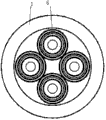
Fig. 1 is the structural representation of the utility model embodiment;
Fig. 2 is for being provided with the structural representation of conical cap one end face among Fig. 1;
Fig. 3 is for being provided with the structural representation of positive truncated cone-shaped cap one end face among Fig. 1.
Embodiment
Below in conjunction with accompanying drawing and specific embodiment, further illustrate the utility model.
Shown in Fig. 1-3, disclosed cable splice closure comprises cylindrical body 1 with the adjustable inlet wire packoff of porous in the present embodiment; The side of body 1 is provided with several annular grooves 2; Body 2 both ends of the surface are provided with four incoming lines 3 that are used to pass cable vertically; Body 1 wherein incoming line 3 places on the end face is provided with positive truncated cone-shaped cap 6, and incoming line 3 places on the other end are provided with conical cap 4, and positive truncated cone-shaped cap 6 and conical cap 4 are with incoming line 3 sealings; During use, on the diverse location of positive truncated cone-shaped cap 6 and conical cap 4, cut off mouth, cable 5 is penetrated according to the size of cable 5 diameters; Porous is adjustable, and the inlet wire packoff is installed on the cable splice closure through the annular groove on it 2.
On body 1 both ends of the surface two relative incoming lines 3 be positioned at 1 parallel straight line of body on.
The above only is the preferred implementation of the utility model; Should be pointed out that for those skilled in the art, under the prerequisite that does not break away from the utility model principle; Can also make some improvement, these improve the protection domain that also should be regarded as the utility model.
Claims (4)
1. a cable splice closure is characterized in that: comprise cylindrical body (1) with the adjustable inlet wire packoff of porous; The side of said body (1) is provided with several annular grooves (2); Body (2) both ends of the surface are provided with a plurality of incoming lines (3) that are used to pass cable vertically; Said incoming line (3) locates to be provided with conical cap (4), and conical cap (4) seals incoming line (3); During use, on the diverse location of conical cap (4), cut off mouth, cable (5) is penetrated according to the size of cable (5) diameter; Said porous is adjustable, and the inlet wire packoff is installed on the cable splice closure through the annular groove on it (2).
2. cable splice closure as claimed in claim 1 is characterized in that with the adjustable inlet wire packoff of porous: said body (1) the wherein incoming line (3) on the end face locates to be provided with positive truncated cone-shaped cap (6), and the incoming line on the other end (3) locates to be provided with conical cap (4).
3. cable splice closure as claimed in claim 1 is with the adjustable inlet wire packoff of porous, and it is characterized in that: the cable at clip is provided with packoff, and said packoff is a sealing joint strip.
4. cable splice closure as claimed in claim 1 is characterized in that with the adjustable inlet wire packoff of porous: be equipped with four incoming lines (3) on said body (1) both ends of the surface, relative two incoming lines (3) are positioned on the straight line parallel with body (1) axle.
Priority Applications (1)
| Application Number | Priority Date | Filing Date | Title |
|---|---|---|---|
| CN2012201067804U CN202494821U (en) | 2012-03-20 | 2012-03-20 | Porous adjustable inlet wire sealing device for cable connector box |
Applications Claiming Priority (1)
| Application Number | Priority Date | Filing Date | Title |
|---|---|---|---|
| CN2012201067804U CN202494821U (en) | 2012-03-20 | 2012-03-20 | Porous adjustable inlet wire sealing device for cable connector box |
Publications (1)
| Publication Number | Publication Date |
|---|---|
| CN202494821U true CN202494821U (en) | 2012-10-17 |
Family
ID=47001044
Family Applications (1)
| Application Number | Title | Priority Date | Filing Date |
|---|---|---|---|
| CN2012201067804U Expired - Lifetime CN202494821U (en) | 2012-03-20 | 2012-03-20 | Porous adjustable inlet wire sealing device for cable connector box |
Country Status (1)
| Country | Link |
|---|---|
| CN (1) | CN202494821U (en) |
Cited By (3)
| Publication number | Priority date | Publication date | Assignee | Title |
|---|---|---|---|---|
| WO2014139102A1 (en) * | 2013-03-13 | 2014-09-18 | 3M Innovative Properties Company | Sealing tube for cable entry port |
| CN107078389A (en) * | 2014-10-16 | 2017-08-18 | 飞利浦照明控股有限公司 | Power supply cable, driver device with wireless control function and control method |
| CN111180949A (en) * | 2020-02-21 | 2020-05-19 | 嘉兴市盛央电气有限公司 | A combined waterproof threading board |
-
2012
- 2012-03-20 CN CN2012201067804U patent/CN202494821U/en not_active Expired - Lifetime
Cited By (3)
| Publication number | Priority date | Publication date | Assignee | Title |
|---|---|---|---|---|
| WO2014139102A1 (en) * | 2013-03-13 | 2014-09-18 | 3M Innovative Properties Company | Sealing tube for cable entry port |
| CN107078389A (en) * | 2014-10-16 | 2017-08-18 | 飞利浦照明控股有限公司 | Power supply cable, driver device with wireless control function and control method |
| CN111180949A (en) * | 2020-02-21 | 2020-05-19 | 嘉兴市盛央电气有限公司 | A combined waterproof threading board |
Similar Documents
| Publication | Publication Date | Title |
|---|---|---|
| CN202494821U (en) | Porous adjustable inlet wire sealing device for cable connector box | |
| CN206471517U (en) | A kind of new indoor Cheng Duan for lightning protection | |
| CN205719394U (en) | High pressure impact resistance pressure transducer | |
| CN204116667U (en) | Both-end mechanical seal cable splice closure | |
| CN203480075U (en) | Optical fiber hot melting protection casing | |
| CN203051951U (en) | Cable distribution device | |
| CN201877747U (en) | Terminal box | |
| CN207263986U (en) | A kind of skin fibre cable terminal box | |
| CN202496155U (en) | Porous threading sealing device for Hubble connector | |
| CN204684415U (en) | A kind of seal wire protector | |
| CN201556895U (en) | Cable sleeve | |
| CN206234483U (en) | A kind of pipe box cupling for petroleum pipeline gripping docking | |
| CN205581370U (en) | Optical cable terminal box | |
| CN204598259U (en) | A kind of anti-breaking earphones | |
| CN204290255U (en) | A kind of difunctional cable with seal protection cover | |
| CN204129289U (en) | Optical-fibre distribution box | |
| CN204835456U (en) | A insulator cap for cable interface | |
| CN205229517U (en) | Optic fibre water joint | |
| CN204028172U (en) | The copper connector assembly of termination | |
| CN203230949U (en) | Flat cable hanging device | |
| CN206422313U (en) | A kind of novel wire protective sleeve | |
| CN204858099U (en) | A external power socket for yacht | |
| CN201797061U (en) | 10-35kV high-voltage pothead KFD connection device | |
| CN201352697Y (en) | Assemble type guide plug | |
| CN210577575U (en) | But quick assembly disassembly's cable line connector |
Legal Events
| Date | Code | Title | Description |
|---|---|---|---|
| C14 | Grant of patent or utility model | ||
| GR01 | Patent grant | ||
| CX01 | Expiry of patent term |
Granted publication date: 20121017 |
|
| CX01 | Expiry of patent term |