CN202497897U - Bracket seat of jaw crusher - Google Patents
Bracket seat of jaw crusher Download PDFInfo
- Publication number
- CN202497897U CN202497897U CN201220126831XU CN201220126831U CN202497897U CN 202497897 U CN202497897 U CN 202497897U CN 201220126831X U CN201220126831X U CN 201220126831XU CN 201220126831 U CN201220126831 U CN 201220126831U CN 202497897 U CN202497897 U CN 202497897U
- Authority
- CN
- China
- Prior art keywords
- seat
- bracket seat
- bracket
- adjustment
- jaw crusher
- Prior art date
- Legal status (The legal status is an assumption and is not a legal conclusion. Google has not performed a legal analysis and makes no representation as to the accuracy of the status listed.)
- Expired - Fee Related
Links
- 238000012423 maintenance Methods 0.000 abstract description 2
Images


Landscapes
- Crushing And Grinding (AREA)
Abstract
The utility model discloses a bracket seat of a jaw crusher, wherein the cross section of the bracket seat (1) is trapezoidal; a corresponding dovetail groove (3) is arranged on an adjustment seat (2); and the bracket seat (1) is arranged in the dovetail groove (3) of the adjustment seat (2). The bracket seat provided by the utility model is in tapered connection with the adjustment seat and then the bracket seat can be easily taken out from the adjustment seat, so that the change of the bracket seat is easy, the change time is short, the work efficiency is high and the maintenance cost is low.
Description
Technical field
The utility model relates to jaw crusher, is specifically related to a kind of bracket seat of jaw crusher.
Background technology
As everyone knows; The bracket seat of jaw crusher is installed in the rectangular channel of adjustment seat, the bracket seat through with the impact wear many times of bracket after, gross distortion when needing to change; The bracket seat has embedded in the adjustment seat; Be difficult to directly from the adjustment seat, take out, need could take out with the flame cutting, time-consuming.
Summary of the invention
The purpose of the utility model is: a kind of bracket seat of jaw crusher is provided, and the bracket seat takes out from the adjustment seat at an easy rate, greatly shortens the replacing time, increases work efficiency.
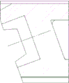
The purpose of the utility model reaches through following measure: the cross section of this bracket seat is trapezoidal, drives corresponding dovetail groove on the adjustment seat, and the bracket seat is installed in the dovetail groove of adjustment seat.
The bracket seat of the utility model is cooperating of band tapering with the adjustment seat, and the bracket seat is easy to from the adjustment seat, take out, and the bracket seat is changed easily, and the replacing time is short, high efficiency, and maintenance cost is low.
Description of drawings
Fig. 1 is the complete machine design sketch before revising.
Fig. 2 is bracket seat before revising and adjustment seat.
Fig. 3 is the complete machine design sketch of the utility model.
Fig. 4 is the bracket seat and adjustment seat of the utility model.
Among the figure: 1 bracket seat, 2 adjustment seats, 3 dovetail grooves.
The specific embodiment
Like Fig. 3, shown in 4, the cross section of this bracket seat 1 is trapezoidal, drives corresponding dovetail groove 3 on the adjustment seat 2, and bracket seat 1 is installed in the dovetail groove 3 of adjustment seat 2.
Claims (1)
1. the bracket seat of jaw crusher, it is characterized in that: the cross section of this bracket seat (1) is trapezoidal, drives corresponding dovetail groove (3) on the adjustment seat (2), bracket seat (1) is installed in the dovetail groove (3) of adjustment seat (2).
Priority Applications (1)
| Application Number | Priority Date | Filing Date | Title |
|---|---|---|---|
| CN201220126831XU CN202497897U (en) | 2012-03-30 | 2012-03-30 | Bracket seat of jaw crusher |
Applications Claiming Priority (1)
| Application Number | Priority Date | Filing Date | Title |
|---|---|---|---|
| CN201220126831XU CN202497897U (en) | 2012-03-30 | 2012-03-30 | Bracket seat of jaw crusher |
Publications (1)
| Publication Number | Publication Date |
|---|---|
| CN202497897U true CN202497897U (en) | 2012-10-24 |
Family
ID=47034525
Family Applications (1)
| Application Number | Title | Priority Date | Filing Date |
|---|---|---|---|
| CN201220126831XU Expired - Fee Related CN202497897U (en) | 2012-03-30 | 2012-03-30 | Bracket seat of jaw crusher |
Country Status (1)
| Country | Link |
|---|---|
| CN (1) | CN202497897U (en) |
-
2012
- 2012-03-30 CN CN201220126831XU patent/CN202497897U/en not_active Expired - Fee Related
Similar Documents
| Publication | Publication Date | Title |
|---|---|---|
| CL2018001519A1 (en) | Control of an excavation operation of an industrial machine | |
| MX361972B (en) | Vertical shaft impactor. | |
| WO2013003047A3 (en) | Hydraulic control system having swing motor energy recovery | |
| WO2014028713A3 (en) | Replaceable wear plates for use with blind shear rams | |
| GB201309361D0 (en) | Method for operating an engine | |
| MX2015007721A (en) | Improved transfer medium. | |
| MX2015010929A (en) | Gearbox housing and method for producing a gearbox housing. | |
| ZA201300035B (en) | Assembly,operating method and circuit for a mill driven by a ring motor | |
| IN2014MN01621A (en) | ||
| WO2012103904A3 (en) | Method and device for determining the load flow in a power supply network | |
| AU2012222515A8 (en) | Fin and installation for converting hydraulic energy comprising such a fin | |
| CN102974736A (en) | Positioning structure for turbine blade blank | |
| GEP20156296B (en) | Curved conduit pertaining to hydraulic machine, distribution group for pelton turbine wheel, and hydraulic machine | |
| CN202846214U (en) | Round tool locating device on milling machine | |
| CN202992313U (en) | Inblock cast power cutting pilot control valve body type pilot valve | |
| CN103406900A (en) | Rotating arm type mechanical hand | |
| CN204308103U (en) | Aperture gradual change type waste steel bar straightening module | |
| CN202122973U (en) | Toothed plate of high-manganese jaw breaker | |
| CN204171362U (en) | A kind of cutter mechanism for turning hydraulic cylinder piston rod | |
| CN203092219U (en) | Planomiller main shaft hydraulic speed control system | |
| CN202436201U (en) | Waistband | |
| CN202642814U (en) | Feeding seat for particle machine | |
| CN204402881U (en) | A kind of split type lateral plate structure | |
| CN202438672U (en) | Wear-resistant hammer head for die casting machine | |
| CN202962559U (en) | Wear-resisting hammer splint |
Legal Events
| Date | Code | Title | Description |
|---|---|---|---|
| C14 | Grant of patent or utility model | ||
| GR01 | Patent grant | ||
| C17 | Cessation of patent right | ||
| CF01 | Termination of patent right due to non-payment of annual fee |
Granted publication date: 20121024 Termination date: 20130330 |