CN202808240U - Gear locator - Google Patents
Gear locator Download PDFInfo
- Publication number
- CN202808240U CN202808240U CN 201220452888 CN201220452888U CN202808240U CN 202808240 U CN202808240 U CN 202808240U CN 201220452888 CN201220452888 CN 201220452888 CN 201220452888 U CN201220452888 U CN 201220452888U CN 202808240 U CN202808240 U CN 202808240U
- Authority
- CN
- China
- Prior art keywords
- gear
- tappet
- spring
- sleeve pipe
- adjusting sleeve
- Prior art date
- Legal status (The legal status is an assumption and is not a legal conclusion. Google has not performed a legal analysis and makes no representation as to the accuracy of the status listed.)
- Expired - Fee Related
Links
- 229910000831 Steel Inorganic materials 0.000 abstract description 4
- 239000010959 steel Substances 0.000 abstract description 4
- 230000000694 effects Effects 0.000 description 3
- XEEYBQQBJWHFJM-UHFFFAOYSA-N Iron Chemical compound [Fe] XEEYBQQBJWHFJM-UHFFFAOYSA-N 0.000 description 2
- 238000006243 chemical reaction Methods 0.000 description 2
- 230000006835 compression Effects 0.000 description 2
- 238000007906 compression Methods 0.000 description 2
- 238000004804 winding Methods 0.000 description 2
- 230000009286 beneficial effect Effects 0.000 description 1
- 238000000354 decomposition reaction Methods 0.000 description 1
- 238000005516 engineering process Methods 0.000 description 1
- 230000003993 interaction Effects 0.000 description 1
- 229910052742 iron Inorganic materials 0.000 description 1
- 238000005272 metallurgy Methods 0.000 description 1
- 230000001105 regulatory effect Effects 0.000 description 1
- 238000000926 separation method Methods 0.000 description 1
Images

Landscapes
- Gears, Cams (AREA)
Abstract
The utility model relates to a gear locator, which is arranged on a gear case. The gear locator comprises a gear handle, a tappet, an adjusting casing pipe, and a spring, wherein the gear case is movably connected with the upper part of the gear handle; one end of the tappet is connected with the gear handle; one end of the adjusting casing pipe is sleeved on the other end of the tappet, and the other end of the adjusting casing pipe is arranged on a fixing shaft of the gear case in a fork way; one end of the spring is sleeved on the body of the tappet body, and the other end of the spring is sleeved on the adjusting casing pipe and is adjusted through an adjusting bolt on the adjusting casing pipe. The gear locator provided by the utility model can reduce the damage of a gear bearing, and the a gear is very convenient to change when a steel wire rope is changed.
Description
Technical field
The utility model relates to loading-unload machine, particularly a kind of gear steady arm.
Background technology
In the epoch of loading-unload machine upgrading development, ship unloaders and bridge-type container handling crane have become the indispensable lifting gear of modern logistics.Ship unloaders and bridge-type container crane facility have been widely used in container wharf, power plant, metallurgy, the loading and unloading such as grain industry.
Four winding drum gear punch-out equipment hook is the mechanical part that the steel rope of ship unloaders and bridge-type container handling crane batches, that four winding drum machine hook has mutual interaction relation during normal operation, the effect of gear is to make four reels play separation or merge to carry out work, the location of gear: former design is rigid fixing, in the middle of operation, small size chatter phenomena is arranged at real work middle gear case, make original rigid connection be easy to damage, so operative employee or maintainer in the middle of the use at ordinary times do not adopt rigid connection and the mode (certain toughness is arranged like this) of always taking up with iron wire but to carry out the work of taking up of not timing in the middle of the work always, one has carelessness will cause the damage of inner gear of the gear box or the damage of gear bearing.
It is bright to send out content
The purpose of this utility model is to design a kind of gear steady arm, can reduce the damage of gear bearing, and the simultaneously gear conversion when change steel rope more also becomes very convenient.
For achieving the above object, the technical solution of the utility model is:
A kind of gear steady arm is installed on the gear case, and it comprises, gear hand shank, and its top movable is connected on the gear case; Tappet, an end connects with gear hand shank; Adjusting sleeve pipe, an end is sheathed on the tappet other end, and adjusting sleeve pipe one end yoke is located on the anchor shaft of gear case; Spring, an end is sheathed on the tappet shaft, and the other end is sheathed on adjusting sleeve pipe, and by the adjusting nut adjustment on the adjusting sleeve pipe.
Further, the end that described tappet is connected with gear hand shank is offered groove, and described gear hand shank is embedded in this groove, and is flexibly connected by bolt and tappet.
The tappet of registration device connects the gear hand shank other end and is enclosed within the adjusting sleeve pipe; adjusting sleeve pipe is comprised of spring and adjusting nut; one of spring pushes away the tappet other end and pushes down setting nut; the sway capable of regulating tappet of nut is to the precompressed compression of handle; the small size vibration of gear can have spring to absorb in the realization work, reaches the effect of protection.Per tour is adjusted preloading spring, makes it that certain thrust be arranged, but must not kill spring, makes it can't absorb the small size vibration of gear.
The beneficial effects of the utility model:
After the utility model gear registration device installed, it is few that the damage of gear bearing obviously changes, and the simultaneously gear conversion when change steel rope more also becomes very convenient.
Description of drawings
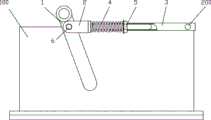
Fig. 1 is the structural representation of the utility model embodiment.
Fig. 2 is the STRUCTURE DECOMPOSITION figure of tappet, adjusting sleeve pipe etc. among the utility model embodiment.
The specific embodiment
Referring to Fig. 1, Fig. 2, a kind of gear steady arm of the present utility model is installed on the gear case 100, and it comprises, gear hand shank 1, and its top movable is connected on the gear case 100; Tappet 2, one ends connect with gear hand shank 1; Adjusting sleeve pipe 3, one ends are sheathed on tappet 2 other ends, and adjusting sleeve pipe 3 one end yokes are located on the anchor shaft 200 of gear case 100; Spring 4, one ends are sheathed on tappet 2 shafts, and the other end is sheathed on adjusting sleeve pipe 3, and adjust spring pressure by the adjusting nut 5 on the adjusting sleeve pipe 3.
Further, the end that described tappet 2 is connected with gear hand shank 1 is offered groove 21, and described gear hand shank 1 is embedded in this groove 21, and is flexibly connected by bolt 6 and tappet 2.
The utility model gear steady arm is adjusted tappet to the precompressed compression of handle by the sway of adjusting nut, and the small size vibration of gear can be absorbed by spring in the realization work, reaches the effect of protection.Need before using spring is adjusted, make it that certain thrust be arranged, but must not kill spring, make it can't absorb the small size vibration of gear.
Claims (2)
1. a gear steady arm is installed on the gear case, it is characterized in that, comprise,
Gear hand shank, its top movable is connected on the gear case;
Tappet, an end connects with gear hand shank;
Adjusting sleeve pipe, an end is sheathed on the tappet other end, and adjusting sleeve pipe one end yoke is located on the anchor shaft of gear case;
Spring, an end is sheathed on the tappet shaft, and the other end is sheathed on adjusting sleeve pipe, and by the adjusting nut adjustment on the adjusting sleeve pipe.
2. gear steady arm as claimed in claim 1 is characterized in that, the end that described tappet is connected with gear hand shank is offered groove, and described gear hand shank is embedded in this groove, and is flexibly connected by bolt and tappet.
Priority Applications (1)
| Application Number | Priority Date | Filing Date | Title |
|---|---|---|---|
| CN 201220452888 CN202808240U (en) | 2012-09-06 | 2012-09-06 | Gear locator |
Applications Claiming Priority (1)
| Application Number | Priority Date | Filing Date | Title |
|---|---|---|---|
| CN 201220452888 CN202808240U (en) | 2012-09-06 | 2012-09-06 | Gear locator |
Publications (1)
| Publication Number | Publication Date |
|---|---|
| CN202808240U true CN202808240U (en) | 2013-03-20 |
Family
ID=47867161
Family Applications (1)
| Application Number | Title | Priority Date | Filing Date |
|---|---|---|---|
| CN 201220452888 Expired - Fee Related CN202808240U (en) | 2012-09-06 | 2012-09-06 | Gear locator |
Country Status (1)
| Country | Link |
|---|---|
| CN (1) | CN202808240U (en) |
-
2012
- 2012-09-06 CN CN 201220452888 patent/CN202808240U/en not_active Expired - Fee Related
Similar Documents
| Publication | Publication Date | Title |
|---|---|---|
| GB201216458D0 (en) | Handling loads in offshore environments | |
| MY198330A (en) | Transportable Inline Heave Compensator | |
| CN102897545B (en) | Special motor-driven tube overturning machine for magnetic powder material tube | |
| CN203558749U (en) | Wet type mixing granulator stirring paddle lifting mechanism | |
| CN202321978U (en) | Combined lifting appliance for metallurgical environment | |
| CN202579879U (en) | Input wheel of worm-gear speed reducer with friction function | |
| CN202808240U (en) | Gear locator | |
| CN201367312Y (en) | Loading suspender of platform | |
| CN202497939U (en) | Through axle type magnetic separator roller | |
| CN204607375U (en) | A kind of stone tongs | |
| CN208758961U (en) | One kind pulling out shaft device | |
| CN202670990U (en) | Container spreader upper support | |
| CN204265331U (en) | A kind of fuel line hanger | |
| CN203936918U (en) | A kind of manipulator | |
| CN204265307U (en) | The structure that a kind of foreign material peculiar to vessel hang | |
| CN103991081A (en) | Mechanical arm | |
| CN203403875U (en) | Resistance-meeting display device of forty-arm caliper | |
| CN201687387U (en) | Rotary carrying device in top-driving well drilling device | |
| CN203602231U (en) | Hanging hook device and crane | |
| CN201545617U (en) | Anti-dropping locating device for trolley walking wheel of tower crane | |
| CN201685261U (en) | Portable loading and unloading machine | |
| CN204265222U (en) | Sintering pallet Novel hanging tool | |
| CN204505143U (en) | End cover of pressure container vertical elevator structure | |
| CN204265348U (en) | A kind of foreign material hang | |
| CN202492279U (en) | Positioning cable |
Legal Events
| Date | Code | Title | Description |
|---|---|---|---|
| C14 | Grant of patent or utility model | ||
| GR01 | Patent grant | ||
| CF01 | Termination of patent right due to non-payment of annual fee |
Granted publication date: 20130320 Termination date: 20150906 |
|
| EXPY | Termination of patent right or utility model |