CN203166350U - Cooling system of distribution box set - Google Patents
Cooling system of distribution box set Download PDFInfo
- Publication number
- CN203166350U CN203166350U CN 201320095825 CN201320095825U CN203166350U CN 203166350 U CN203166350 U CN 203166350U CN 201320095825 CN201320095825 CN 201320095825 CN 201320095825 U CN201320095825 U CN 201320095825U CN 203166350 U CN203166350 U CN 203166350U
- Authority
- CN
- China
- Prior art keywords
- distribution box
- pipeline
- cooling
- cooling system
- pipelines
- Prior art date
- Legal status (The legal status is an assumption and is not a legal conclusion. Google has not performed a legal analysis and makes no representation as to the accuracy of the status listed.)
- Expired - Fee Related
Links
Images


Landscapes
- Cooling Or The Like Of Electrical Apparatus (AREA)
Abstract
The utility model discloses a cooling system of a distribution box set. The cooling system comprises a plurality of distribution box bodies, and the plurality of distribution box bodies are provided with connected pipelines. The pipelines inside the distribution box bodies are provided with buckles, and the buckles are provided with through holes. The pipelines are connected with a water pump. A power distribution module is installed on the buckle, so heat generated by working of the power distribution module conducted to the pipeline. Cooling water in the pipelines is driven by the water pump, and heat of the pipelines is conducted to the cooling water. Hot cooling water is cooled down in a cooling tower and then is recycled to use. Using a buckle structure, the power distribution modules can be installed on different positions in different number according to requirements of different distribution boxes. Installation precision is improved, and processing and installation are convenient.
Description
Technical field
The utility model relates to the power distribution equipment in a kind of electric power system, especially relates to a kind of power distribution panel, particularly a kind of cooling system of distribution box group.
Background technology
In electric power system, for electric current distribution and the control of various partial powers, need in distribution box, carry out usually, it is equivalent to a small-sized power hub.Common, enter distribution box by many wires, after each Power entry module is partly realized the control of electric power and distributed, flow out distribution boxs by many wires again, partly realize control and the distribution of electric power at described Power entry module.
And the Power entry module work meeting of distribution box inside produces heat, in the inner complicated electric power system of distribution box, a large amount of Power entry modules is installed, therefore can produce a large amount of heats, the danger that more can burn because of the too high generation Power entry module of temperature each component life, the especially summer that a large amount of heats can influence Power entry module.
Thereby the sidewall of general distribution box all can be provided with ventilation hole, but ventilation hole only adopts the ventilation hole heat radiation for outside air temperature just under the very high situation in summer own, and radiating effect is very undesirable.Also have some manufacturing enterprises to add fan in distribution box, though fan is installed and is only adopted ventilation hole to compare can to improve radiating effect, fan itself will consume much electricity, produces a lot of heats, the cost height that therefore dispels the heat, and effect is also undesirable.
Summary of the invention
The utility model provides a kind of cooling system of distribution box group at the prior art deficiency, and the cooling system of this kind distribution box group can effectively improve radiating effect, and go for installing the different distribution box of Power entry module status requirement, and process easy for installation, with low cost, convenient management.
In order to solve the problems of the technologies described above, the utility model is solved by following technical proposals: a kind of cooling system of distribution box group, comprise some distribution box bodies, be provided with continuous pipeline in some described distribution box bodies, on the pipeline of described distribution box body interior buckle is set, described buckle is provided with through hole, and described pipeline is connected with water pump.Be provided with for the pipeline by cooling water in the described distribution box body, through hole on the described buckle is used for installing Power entry module, the heat that Power entry module produces can be transmitted on the described pipeline, heat on the described pipeline is transmitted in the cooling water, described water pump drives described ducted cooling water motion, take away the heat in the distribution box, thereby raising cooling effect, and as long as just can control a large amount of distribution box coolings by a water pump, can switch off the pump when distribution box does not need the cooling water heat radiation when low temperature cuts the waste.
In the technique scheme, preferred, described pipeline joins end to end, and also is connected with cooling tower on the described pipeline, and ducted cooling water is formed the loop and adopts cooling tower to reduce the temperature of the cooling water of heating, improves radiating effect with this.
In the technique scheme, for better heat radiation, also be provided with fin on described pipeline, fin helps to improve heat exchange area, makes that the heat exchange area between the air in pipeline and the distribution box becomes big, thereby improves the efficient of heat exchange, improves radiating effect.
In order to guarantee that described distribution box body and described pipeline have enough intensity and sealing effectiveness, described distribution box body and described pipeline adopt welding fixing.
The utility model compared with prior art, have following beneficial effect: the utility model is by being installed in Power entry module on the buckle, the heat that makes Power entry module work produce is transmitted on the pipeline, ducted cooling water adopts water pump to drive, heat on the pipeline is transmitted in the cooling water, after lowering the temperature in cooling tower, the cooling water of heat continues to recycle, adopt buckle structure to install according to Power entry module diverse location and quantity that different distribution box needs are installed, improve installation accuracy, and process easy for installation.
Description of drawings
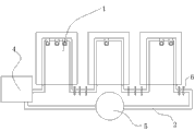
Fig. 1 is the schematic diagram of the utility model embodiment.
Fig. 2 is the front view of the utility model embodiment buckle.
Fig. 3 is the right view of buckle.
Embodiment
Below in conjunction with accompanying drawing and embodiment the utility model is described in further detail: referring to Fig. 1 to Fig. 3, a kind of cooling system of distribution box group, comprise some distribution box bodies 1, be provided with continuous pipeline 2 in some described distribution box bodies 1, on the pipeline 2 of described distribution box body 1 inside buckle 3 is set, described buckle 3 is provided with through hole 31, and described pipeline 2 is connected with water pump 4.Be provided with in the described distribution box body 1 for the pipeline 2 by cooling water, through hole 31 on the described buckle 3 is used for installing Power entry module, the heat that Power entry module produces can be transmitted on the described pipeline 2, heat on the described pipeline 2 is transmitted in the cooling water, described water pump 4 drives the cooling water motion in the described pipeline 2, take away the heat in the distribution box body 1, thereby raising cooling effect, and as long as just can control the cooling of a large amount of distribution box by a water pump 4, can switch off the pump when distribution box does not need cooling water to dispel the heat when low temperature 4 cuts the waste.The cooling system of this distribution box group is each local distribution box in the structure of inside employing cooling water pipeline 2 and buckle 3 can be applied to live, more can utilize the water that constantly flows in the water supply pipe 2 as cooling water, utilizing just needs the running water of operation to do cooling water originally, has realized not having substantially the heat radiation of energy consumption.
Described pipeline 2 joins end to end, and also is connected with cooling tower 5 on the described pipeline 2, the cooling water in the pipeline 2 is formed the loop and adopt cooling tower 5 to reduce the temperature of the cooling water of heating, improves radiating effect with this.This kind scheme is applicable to the factory that distribution box is relatively concentrated etc. more, and it is not enough that these local distribution boxs may be done water quench efficient with running water, therefore needs cooling tower 5 to lower the temperature.
For better heat radiation, on described pipeline 2, also be provided with fin 6, fin 6 helps to improve heat exchange area, makes that the heat exchange area between the air in pipeline 2 and the distribution box body 1 becomes big, thereby improves the efficient of heat exchange, improves radiating effect.
Described distribution box body 1 adopts welding fixing to guarantee that pipeline 2 and distribution box body 1 have enough intensity and sealing effectiveness with described pipeline 2.
Claims (4)
1. the cooling system of a distribution box group, it is characterized in that: comprise some distribution box bodies (1), be provided with continuous pipeline (2) in some described distribution box bodies (1), on the pipeline (2) of described distribution box body (1) inside buckle (3) is set, described buckle (3) is provided with through hole (31), and described pipeline is connected with water pump (4).
2. the cooling system of a kind of distribution box group as claimed in claim 1, it is characterized in that: described pipeline (2) joins end to end, and also is connected with cooling tower (5) on the described pipeline.
3. the cooling system of a kind of distribution box group as claimed in claim 1 is characterized in that: also be provided with fin (6) on the described pipeline (2).
4. the cooling system of a kind of distribution box group as claimed in claim 1 is characterized in that: described distribution box body (1) adopts welding fixing with described pipeline (2).
Priority Applications (1)
| Application Number | Priority Date | Filing Date | Title |
|---|---|---|---|
| CN 201320095825 CN203166350U (en) | 2013-03-04 | 2013-03-04 | Cooling system of distribution box set |
Applications Claiming Priority (1)
| Application Number | Priority Date | Filing Date | Title |
|---|---|---|---|
| CN 201320095825 CN203166350U (en) | 2013-03-04 | 2013-03-04 | Cooling system of distribution box set |
Publications (1)
| Publication Number | Publication Date |
|---|---|
| CN203166350U true CN203166350U (en) | 2013-08-28 |
Family
ID=49027510
Family Applications (1)
| Application Number | Title | Priority Date | Filing Date |
|---|---|---|---|
| CN 201320095825 Expired - Fee Related CN203166350U (en) | 2013-03-04 | 2013-03-04 | Cooling system of distribution box set |
Country Status (1)
| Country | Link |
|---|---|
| CN (1) | CN203166350U (en) |
Cited By (4)
| Publication number | Priority date | Publication date | Assignee | Title |
|---|---|---|---|---|
| CN105790134A (en) * | 2016-03-11 | 2016-07-20 | 江苏镇安电力设备有限公司 | Box-type substation structure protection method preventing corrosion, mould and high temperature |
| CN106025865A (en) * | 2016-07-18 | 2016-10-12 | 安徽得润电气技术有限公司 | Low-voltage distribution box with heat radiating system |
| CN107732720A (en) * | 2017-10-31 | 2018-02-23 | 普元电力发展有限公司 | A kind of communication type water-cooling type electrician's cabinet |
| CN108471060A (en) * | 2018-04-17 | 2018-08-31 | 江苏力沛电力工程技术服务有限公司 | A kind of power engineering equipment and application method |
-
2013
- 2013-03-04 CN CN 201320095825 patent/CN203166350U/en not_active Expired - Fee Related
Cited By (4)
| Publication number | Priority date | Publication date | Assignee | Title |
|---|---|---|---|---|
| CN105790134A (en) * | 2016-03-11 | 2016-07-20 | 江苏镇安电力设备有限公司 | Box-type substation structure protection method preventing corrosion, mould and high temperature |
| CN106025865A (en) * | 2016-07-18 | 2016-10-12 | 安徽得润电气技术有限公司 | Low-voltage distribution box with heat radiating system |
| CN107732720A (en) * | 2017-10-31 | 2018-02-23 | 普元电力发展有限公司 | A kind of communication type water-cooling type electrician's cabinet |
| CN108471060A (en) * | 2018-04-17 | 2018-08-31 | 江苏力沛电力工程技术服务有限公司 | A kind of power engineering equipment and application method |
Similar Documents
| Publication | Publication Date | Title |
|---|---|---|
| CN202978042U (en) | Water cooling heat radiation system of power distribution cabinet | |
| CN103855630A (en) | Power distribution cabinet heat-dissipation system | |
| CN204012340U (en) | Brass electroplating production line power distribution cabinet water cooling plant | |
| CN203574606U (en) | Air-cooling and water-cooling combined solar cell structure | |
| CN205001129U (en) | Directly drive empty cooling system of empty water of wind generating set generator | |
| CN103162202A (en) | High-efficiency heat dissipating street lamp | |
| CN203467361U (en) | Intelligent spray disinfection system of energy saving breeding room | |
| CN205230713U (en) | Solar energy transformer cooling device | |
| CN204408221U (en) | Automobile tail gas heat-energy recovering apparatus | |
| CN102889827A (en) | Water cooling system | |
| CN204461132U (en) | A kind of energy-saving power-boost generating cooling tower systems | |
| CN203072301U (en) | Heat radiation structure of mining electronic locomotive controller | |
| CN203119351U (en) | Distribution box with circulating cooling water | |
| CN117888659A (en) | A ventilation and heat exchange energy-saving photovoltaic curtain wall system | |
| CN211150270U (en) | Solar transformer cooling device | |
| CN204156806U (en) | Integral type solar photovoltaic cell panel temperature-controlling system | |
| CN202764082U (en) | Water-cooling device of hot-pressing mold of wind-power blade | |
| CN210444732U (en) | Cooling device of power supply | |
| CN203177689U (en) | Cooling tower without electric fan | |
| CN203796504U (en) | Energy-saving cooling system of wind turbine generating set frequency converter | |
| CN203293333U (en) | Constant-temperature house system operated by utilizing air compressor waste heat | |
| CN208820712U (en) | A kind of photovoltaic plant summer electricity lifting system | |
| CN203119353U (en) | Distribution box with adjusting function of circulating cooling water | |
| CN201583188U (en) | Novel automatic temperature control equipment of cooling tower | |
| CN203454379U (en) | Thermal energy converting device |
Legal Events
| Date | Code | Title | Description |
|---|---|---|---|
| C14 | Grant of patent or utility model | ||
| GR01 | Patent grant | ||
| CF01 | Termination of patent right due to non-payment of annual fee |
Granted publication date: 20130828 Termination date: 20140304 |