CN203237694U - Motorcycle accessory suspension line with orientation function - Google Patents
Motorcycle accessory suspension line with orientation function Download PDFInfo
- Publication number
- CN203237694U CN203237694U CN 201320241244 CN201320241244U CN203237694U CN 203237694 U CN203237694 U CN 203237694U CN 201320241244 CN201320241244 CN 201320241244 CN 201320241244 U CN201320241244 U CN 201320241244U CN 203237694 U CN203237694 U CN 203237694U
- Authority
- CN
- China
- Prior art keywords
- frame
- suspension chain
- arc
- suspension
- section
- Prior art date
- Legal status (The legal status is an assumption and is not a legal conclusion. Google has not performed a legal analysis and makes no representation as to the accuracy of the status listed.)
- Expired - Lifetime
Links
Images


Landscapes
- Devices For Conveying Motion By Means Of Endless Flexible Members (AREA)
Abstract
Description
技术领域 technical field
本实用新型涉及摩托车配菜悬挂线,具体指一种带导向功能的摩托车配菜悬挂线,属于流水生产线技术领域。 The utility model relates to a motorcycle side dish suspension line, specifically a motorcycle side dish suspension line with guiding function, which belongs to the technical field of assembly line.
背景技术 Background technique
在摩托车生产装配中,除了主要的用于装配的流水生产线外,往往还辅助配置了配菜线,配菜线用于给装配工人提供装配所需的零部件和配件。配菜线由支撑架、悬挂链和悬挂链导向框三大部分构成,支撑架安装在地面并位于流水线旁,悬挂链导向框为闭合的环状并水平安装在支撑架上端处于悬空状态,悬挂链安装在悬挂链导向框中并在动力驱动下可在悬挂链导向框内朝一个方向(逆时针或顺时针)转动,悬挂链上间隔一定距离设有配件框篮,配件框篮随悬挂链的不断转动而将所需的配件输送到不同的装配岗位。悬挂链导向框通常呈跑道形,同时鉴于悬挂链存在伸缩状况,因此有必要将悬挂链导向框设计为可与悬挂链伸缩相适应的伸缩结构,为此将悬挂链导向框分为四段--两平行的主体段和位于两主体段两端的弧形补偿段,每段弧形补偿段的两端对应插入两平行主体段中,通过插入深浅而调节悬挂链导向框整体周长。在支撑架两端分别设有一定滑轮,弧形补偿段上连接有一根拉绳,拉绳另一端通过定滑轮改变方向后垂直向下并在末端设有一配重块,配重块的重量与悬挂链的张紧力始终平衡,因此可以通过配重块来决定或改变悬挂链张紧力,当悬挂链收缩时,如果收缩力大于配重块的重力,配重块将被拉动上升一定高度,直到悬挂链的张紧力跟配重块的重量再次处于平衡,反之亦然,通过配重块的设置可自动调节悬挂链导向框整体长度。 In the production and assembly of motorcycles, in addition to the main assembly line, there is often an auxiliary dispensing line, which is used to provide assembly workers with parts and accessories required for assembly. The food distribution line is composed of three parts: a support frame, a suspension chain and a suspension chain guide frame. The support frame is installed on the ground and is located next to the assembly line. The chain is installed in the guide frame of the suspension chain and can rotate in one direction (counterclockwise or clockwise) in the guide frame of the suspension chain under power drive. There are accessory frame baskets on the suspension chain at a certain distance, and the accessory frame baskets follow the suspension chain The continuous rotation of the machine transports the required accessories to different assembly positions. The suspension chain guide frame is usually in the shape of a runway, and in view of the expansion and contraction of the suspension chain, it is necessary to design the suspension chain guide frame as a telescopic structure that can adapt to the expansion and contraction of the suspension chain. For this reason, the suspension chain guide frame is divided into four sections- - Two parallel main body sections and arc-shaped compensation sections located at both ends of the two main body sections, the two ends of each arc-shaped compensation section are correspondingly inserted into the two parallel main body sections, and the overall perimeter of the suspension chain guide frame is adjusted by the insertion depth. There are certain pulleys at both ends of the support frame, and a pull rope is connected to the arc compensation section. The other end of the pull rope changes direction through the fixed pulley and then goes vertically downwards and a counterweight is provided at the end. The weight of the counterweight is the same as The tension of the suspension chain is always balanced, so the tension of the suspension chain can be determined or changed through the counterweight. When the suspension chain shrinks, if the contraction force is greater than the gravity of the counterweight, the counterweight will be pulled up to a certain height , until the tension force of the suspension chain is in balance with the weight of the counterweight again, and vice versa, the overall length of the guide frame of the suspension chain can be automatically adjusted through the setting of the counterweight.
但上述配菜线在使用过程中,弧形补偿段常常卡死,影响配菜线的正常使用。究其原因在于,理论上,补偿架只是相对两平行的主体段如图1上下伸缩,但在实际使用过程中,悬挂链受载荷后在动力驱动下运动,转弯处的补偿架也随之受力,如图1所示,在悬挂链逆时针转动时,下方的补偿架就有一个向右的作用力,该作用力将使链条在需要运动方向上产生偏斜,造成不能正常伸缩补偿,从而出现卡死配菜线的状况。 However, during the use of the above-mentioned garnish line, the arc compensation section is often stuck, which affects the normal use of the garnish line. The reason is that, in theory, the compensation frame only expands and contracts up and down relative to the two parallel main sections as shown in Figure 1, but in actual use, the suspension chain moves under the power drive after being loaded, and the compensation frame at the turning is also affected accordingly. Force, as shown in Figure 1, when the suspension chain rotates counterclockwise, the compensation frame below has a rightward force, which will cause the chain to deflect in the direction of movement, resulting in abnormal expansion and compensation. Thereby the situation of stuck side dish line appears.
发明内容 Contents of the invention
针对现有技术存在的上述不足,本实用新型的目的在于提供一种可避免弧形补偿段卡死的摩托车配菜悬挂线。 In view of the above-mentioned deficiencies in the prior art, the purpose of this utility model is to provide a motorcycle side dish suspension line which can avoid the jamming of the arc compensation section.
为了实现上述目的,本实用新型采用的技术方案是这样的: In order to achieve the above object, the technical solution adopted by the utility model is as follows:
一种带导向功能的摩托车配菜悬挂线,包括支撑架、悬挂链和悬挂链导向框,悬挂链导向框水平安装在支撑架上端处于悬空状态,悬挂链安装在悬挂链导向框中,悬挂链导向框由两平行的主体段和位于两主体段两端的弧形补偿段构成,每段弧形补偿段的两端对应插入两平行主体段中;在支撑架两端分别设有一定滑轮,弧形补偿段与拉绳一端连接,拉绳另一端通过定滑轮改变方向后垂直向下并在末端设有一配重块,其特征在于:在悬挂链导向框弧形补偿段上设有防止弧形补偿段形变的支撑横梁,支撑横梁与悬挂链导向框主体段垂直,在支撑横梁上设有两对称的导向装置,导向装置由支持架和位于支持架上的滚动件构成,支持架安装在支撑横梁上,两导向装置的滚动件位于支撑架内侧以通过支撑架对滚动件的限位来阻止弧形补偿段偏摆。 A motorcycle side dish suspension line with guiding function, comprising a support frame, a suspension chain and a suspension chain guide frame, the suspension chain guide frame is horizontally installed on the upper end of the support frame in a suspended state, the suspension chain is installed in the suspension chain guide frame, and the suspension The chain guide frame is composed of two parallel main sections and arc-shaped compensation sections located at both ends of the two main sections. The two ends of each arc-shaped compensation section are correspondingly inserted into the two parallel main sections; The arc compensation section is connected with one end of the stay rope, and the other end of the stay rope changes direction through a fixed pulley and then goes down vertically and a counterweight is provided at the end. The supporting beam is a supporting beam for compensating the deformation of the section. The supporting beam is perpendicular to the main section of the guide frame of the suspension chain. Two symmetrical guiding devices are arranged on the supporting beam. The guiding device is composed of a supporting frame and rolling parts on the supporting frame. The supporting frame is installed on On the support beam, the rolling elements of the two guiding devices are located inside the support frame to prevent the deflection of the arc compensation section through the limit of the rolling elements by the support frame.
进一步地,所述支撑架包括支撑腿和位于支撑腿上的矩形框架,矩形框架由与悬挂链导向框主体段平行的纵向段和位于纵向段两端的横方构成,两导向装置的滚动件位于纵向段内侧并与纵向段内侧滚动接触。 Further, the support frame includes support legs and a rectangular frame located on the support legs, the rectangular frame is composed of a longitudinal section parallel to the main body section of the suspension chain guide frame and horizontal sides located at both ends of the longitudinal section, and the rolling elements of the two guide devices are located at The inner side of the longitudinal section is in rolling contact with the inner side of the longitudinal section.
所述滚动件为深沟球轴承,支持架上设有转销,深沟球轴承安装在转销上可绕转销转动。 The rolling element is a deep groove ball bearing, and the supporting frame is provided with a revolving pin, and the deep groove ball bearing is installed on the revolving pin and can rotate around the revolving pin.
本实用新型在悬挂链伸缩补偿架处设计了两个导向装置,导向装置主要由滚动件兼起导向和限位作用,当补偿架纵向伸缩时,滚动件与纵向段滚动摩擦,此时滚动件起导向作用,以利于伸缩顺畅。当补偿架有向右侧偏摆的趋势时,纵向段对右侧的滚动件进行限位,因为滚动件、导向装置、支撑横梁和弧形补偿段固定在一起,从而阻止弧形补偿段向右偏斜;当补偿架有向左侧偏摆的趋势时,左侧的滚动件起到同样的限位作用,从而使补偿架始终纵向伸缩,而不能左右偏摆,即不随链条受力而偏摆,从而避免了卡滞现象,使配菜线运转正常。 The utility model designs two guiding devices at the telescopic compensating frame of the suspension chain. The guiding device is mainly composed of rolling parts which also play the role of guiding and limiting. It acts as a guide to facilitate smooth expansion and contraction. When the compensation frame tends to yaw to the right, the longitudinal section will limit the rolling element on the right side, because the rolling element, guide device, support beam and arc compensation section are fixed together, thereby preventing the arc compensation section from moving to the right. Right deflection; when the compensation frame has a tendency to sway to the left, the rolling element on the left plays the same limiting role, so that the compensation frame is always stretched longitudinally, and cannot swing left and right, that is, it does not move with the force of the chain. Deflection, thus avoiding the stagnation phenomenon, so that the garnish line can run normally.
附图说明 Description of drawings
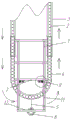
图1-本实用新型结构示意图。 Fig. 1 - structural representation of the utility model.
图2-本实用新型导向装置侧视图。 Fig. 2 - the side view of the guiding device of the present utility model.
图3-本实用新型导向装置俯视图。 Fig. 3 - the top view of the guiding device of the present utility model.
具体实施方式 Detailed ways
下面结合附图对本实用新型作进一步说明。 Below in conjunction with accompanying drawing, the utility model is further described.
参见图1,本实用新型带导向功能的摩托车配菜悬挂线,包括支撑架1、悬挂链2和悬挂链导向框,悬挂链导向框水平安装在支撑架上端处于悬空状态,悬挂链安装在悬挂链导向框中,在动力驱动下,悬挂链可在悬挂链导向框内运动。为了补偿悬挂链的伸缩,悬挂链导向框由两平行的主体段3和位于两主体段两端的弧形补偿段4构成,每段弧形补偿段4的两端对应插入两平行主体段3中。在支撑架1两端分别设有一定滑轮,弧形补偿段4与拉绳5一端连接,拉绳5另一端通过定滑轮改变方向后垂直向下并在末端设有一配重块6,由配重块对悬挂链导向框长度进行自动补偿。在悬挂链导向框弧形补偿段4上设有防止弧形补偿段形变的两支撑横梁7,两支撑横梁7与悬挂链导向框主体段3垂直,在靠近端头的支撑横梁7上设有两对称的导向装置8,导向装置8由支持架9和位于支持架上的滚动件10构成,支持架9固定安装在支撑横梁7上,两导向装置的滚动件10位于支撑架1内侧以通过支撑架对滚动件的限位来阻止弧形补偿段偏摆。导向装置参见图2和图3,滚动件兼起导向和限位作用。
Referring to Fig. 1, the motorcycle side dish suspension line with guide function of the utility model comprises a support frame 1, a suspension chain 2 and a suspension chain guide frame, the suspension chain guide frame is horizontally installed on the support frame upper end and is in a suspended state, and the suspension chain is installed on In the suspension chain guide frame, under power drive, the suspension chain can move in the suspension chain guide frame. In order to compensate for the expansion and contraction of the suspension chain, the suspension chain guide frame is composed of two parallel
进一步地,所述支撑架包括支撑腿和位于支撑腿上的矩形框架,悬挂链导向框由矩形框架进行支撑。矩形框架由与悬挂链导向框主体段平行的纵向段11和位于纵向段两端的横方12构成,定滑轮安装在横方上,两导向装置的滚动件10位于纵向段11内侧并与纵向段11内侧滚动接触。
Further, the supporting frame includes supporting legs and a rectangular frame on the supporting legs, and the suspension chain guide frame is supported by the rectangular frame. The rectangular frame is composed of a
为了安装方便和材料的选择,所述滚动件10为深沟球轴承,支持架上设有竖直向上的转销,深沟球轴承安装在转销上可绕转销转动。
For the convenience of installation and the selection of materials, the
本实用新型在每段悬挂链伸缩补偿架处设计了两个导向装置(两端共四个),导向装置主要由滚动件兼起导向和限位作用,当补偿架纵向伸缩时(这也是设计需要的),滚动件与纵向段滚动摩擦,此时滚动件起导向作用,以利于伸缩顺畅。当补偿架有向右侧偏摆的趋势时(这是运行需要避免的),纵向段对右侧的滚动件进行限位,因为滚动件、导向装置、支撑横梁和弧形补偿段固定在一起,从而由纵向段通过滚动件、导向装置、支撑横梁来阻止弧形补偿段向右偏斜;当补偿架有向左侧偏摆的趋势时,左侧的滚动件起到同样的限位作用,从而使补偿架始终纵向伸缩,而不能左右偏摆,即不随链条受力而偏摆,从而避免了卡滞现象,使配菜线运转正常。 The utility model designs two guiding devices (four ends in total) at each segment of the suspension chain telescopic compensating frame. required), the rolling elements rub against the longitudinal section, and at this time the rolling elements play a guiding role to facilitate smooth expansion and contraction. When the compensation frame has a tendency to yaw to the right (this is to be avoided in operation), the longitudinal section limits the rolling element on the right, because the rolling element, guide, support beam and arc compensation section are fixed together , so that the arc-shaped compensation section is prevented from deflecting to the right by the longitudinal section through the rolling element, the guide device, and the supporting beam; when the compensation frame has a tendency to sway to the left, the rolling element on the left plays the same limiting role , so that the compensation frame is always stretched longitudinally, instead of swinging left and right, that is, it does not swing with the force of the chain, thereby avoiding the stagnation phenomenon and making the distribution line run normally.
最后说明的是,以上实施例仅用以说明本实用新型的技术方案而非限制,尽管参照较佳实施例对本实用新型进行了详细说明,本领域的普通技术人员应当理解,可以对本实用新型的技术方案进行修改或者等同替换,而不脱离本实用新型技术方案的宗旨和范围,其均应涵盖在本实用新型的权利要求范围当中。 Finally, it is noted that the above embodiments are only used to illustrate the technical solutions of the present utility model without limitation. Although the utility model has been described in detail with reference to the preferred embodiments, those of ordinary skill in the art should understand that the utility model can be Modifications or equivalent replacements of the technical solutions without departing from the purpose and scope of the technical solutions of the utility model shall be covered by the claims of the utility model.
Claims (3)
Priority Applications (1)
| Application Number | Priority Date | Filing Date | Title |
|---|---|---|---|
| CN 201320241244 CN203237694U (en) | 2013-05-07 | 2013-05-07 | Motorcycle accessory suspension line with orientation function |
Applications Claiming Priority (1)
| Application Number | Priority Date | Filing Date | Title |
|---|---|---|---|
| CN 201320241244 CN203237694U (en) | 2013-05-07 | 2013-05-07 | Motorcycle accessory suspension line with orientation function |
Publications (1)
| Publication Number | Publication Date |
|---|---|
| CN203237694U true CN203237694U (en) | 2013-10-16 |
Family
ID=49315014
Family Applications (1)
| Application Number | Title | Priority Date | Filing Date |
|---|---|---|---|
| CN 201320241244 Expired - Lifetime CN203237694U (en) | 2013-05-07 | 2013-05-07 | Motorcycle accessory suspension line with orientation function |
Country Status (1)
| Country | Link |
|---|---|
| CN (1) | CN203237694U (en) |
Cited By (1)
| Publication number | Priority date | Publication date | Assignee | Title |
|---|---|---|---|---|
| CN103231893A (en) * | 2013-05-07 | 2013-08-07 | 力帆实业(集团)股份有限公司 | Motorcycle accessory suspension line with guide function |
-
2013
- 2013-05-07 CN CN 201320241244 patent/CN203237694U/en not_active Expired - Lifetime
Cited By (2)
| Publication number | Priority date | Publication date | Assignee | Title |
|---|---|---|---|---|
| CN103231893A (en) * | 2013-05-07 | 2013-08-07 | 力帆实业(集团)股份有限公司 | Motorcycle accessory suspension line with guide function |
| CN103231893B (en) * | 2013-05-07 | 2015-07-01 | 力帆实业(集团)股份有限公司 | Motorcycle accessory suspension line with guide function |
Similar Documents
| Publication | Publication Date | Title |
|---|---|---|
| ES2656704T3 (en) | Elevator installation | |
| CN102303821B (en) | Luffing tower crane with balanced type suspension arm based on traction luffing of steel rope | |
| CN204355754U (en) | Jumbo tire manipulator counter weight device | |
| FI20115289L (en) | Arrangement for dampening the swing of a loading device in a lifting crane | |
| CN203237694U (en) | Motorcycle accessory suspension line with orientation function | |
| CN104229602B (en) | A kind of balance cage | |
| CN106168431A (en) | A kind of height-adjustable shelf assembly and there is its refrigerator | |
| CN209817390U (en) | Hanging basket system for inward-inclined wall construction | |
| CN103231893B (en) | Motorcycle accessory suspension line with guide function | |
| CN201843939U (en) | Auxiliary support device for drag chain | |
| CN204265235U (en) | A kind of lifting hook pulley group | |
| CN209455953U (en) | A kind of synchronization lifting telescopic device for crane | |
| CN204979154U (en) | Telescopic transport arm arm structure | |
| CN204297793U (en) | A kind of high accuracy wire storage device | |
| CN204265070U (en) | Band steel deviation correcting device | |
| ITMI20101302A1 (en) | DEVICE FOR AUTOMATICALLY CHANGING THE CUTTING SYSTEM IN LUMINAIRE APPLIANCES, PARTICULARLY FOR TOWER CRANES. | |
| CN102969669A (en) | Wire releasing pulley for front and back wheels | |
| CN202744211U (en) | Pulley assembly and crane | |
| CN204531349U (en) | Anti-drop device and attachment guide rail anti-falling lifting scaffold | |
| CN205033004U (en) | Raceway is transported to over -and -under type pipe / stick | |
| CN205278754U (en) | A wire rope guiding mechanism of a gas cabinet leveling device | |
| CN102003494A (en) | Ancillary supporting device for drag chain | |
| CN207226667U (en) | Wire-drawing frame tension adjustment mechanism | |
| CN206592501U (en) | A kind of driving-chain strainer | |
| CN204777207U (en) | Flexible band conveyer's unsteady riding wheel structure |
Legal Events
| Date | Code | Title | Description |
|---|---|---|---|
| C14 | Grant of patent or utility model | ||
| GR01 | Patent grant | ||
| AV01 | Patent right actively abandoned |
Granted publication date: 20131016 Effective date of abandoning: 20150701 |
|
| AV01 | Patent right actively abandoned |
Granted publication date: 20131016 Effective date of abandoning: 20150701 |
|
| RGAV | Abandon patent right to avoid regrant |