CN203336070U - Bi-metal composite gas drainage pipeline with coating - Google Patents
Bi-metal composite gas drainage pipeline with coating Download PDFInfo
- Publication number
- CN203336070U CN203336070U CN2013203908620U CN201320390862U CN203336070U CN 203336070 U CN203336070 U CN 203336070U CN 2013203908620 U CN2013203908620 U CN 2013203908620U CN 201320390862 U CN201320390862 U CN 201320390862U CN 203336070 U CN203336070 U CN 203336070U
- Authority
- CN
- China
- Prior art keywords
- pipeline
- coating
- wall
- stainless steel
- steel
- Prior art date
- Legal status (The legal status is an assumption and is not a legal conclusion. Google has not performed a legal analysis and makes no representation as to the accuracy of the status listed.)
- Expired - Fee Related
Links
- 239000011248 coating agent Substances 0.000 title claims abstract description 26
- 238000000576 coating method Methods 0.000 title claims abstract description 26
- 239000002905 metal composite material Substances 0.000 title abstract 2
- 239000010935 stainless steel Substances 0.000 claims abstract description 24
- 229910001220 stainless steel Inorganic materials 0.000 claims abstract description 24
- 229910000831 Steel Inorganic materials 0.000 claims abstract description 19
- 239000010959 steel Substances 0.000 claims abstract description 19
- 229910000975 Carbon steel Inorganic materials 0.000 claims abstract description 17
- 239000010962 carbon steel Substances 0.000 claims abstract description 17
- 239000000463 material Substances 0.000 claims abstract description 15
- 238000003466 welding Methods 0.000 claims abstract description 15
- 238000004804 winding Methods 0.000 claims abstract description 8
- 230000003014 reinforcing effect Effects 0.000 claims abstract description 6
- 239000002131 composite material Substances 0.000 claims description 11
- 238000000605 extraction Methods 0.000 claims description 8
- 238000000034 method Methods 0.000 claims description 8
- 239000000843 powder Substances 0.000 claims description 8
- 239000004698 Polyethylene Substances 0.000 claims description 7
- 239000004593 Epoxy Substances 0.000 claims description 4
- 229920002430 Fibre-reinforced plastic Polymers 0.000 claims description 4
- 239000004721 Polyphenylene oxide Substances 0.000 claims description 4
- 229920002396 Polyurea Polymers 0.000 claims description 4
- 239000003365 glass fiber Substances 0.000 claims description 4
- 239000003973 paint Substances 0.000 claims description 4
- 229920000570 polyether Polymers 0.000 claims description 4
- -1 polyethylene Polymers 0.000 claims description 4
- 229920000573 polyethylene Polymers 0.000 claims description 4
- 238000004049 embossing Methods 0.000 claims description 3
- 230000000694 effects Effects 0.000 abstract description 6
- 239000003245 coal Substances 0.000 abstract description 5
- 239000002184 metal Substances 0.000 abstract 2
- 230000002035 prolonged effect Effects 0.000 abstract 1
- 238000007789 sealing Methods 0.000 abstract 1
- VNWKTOKETHGBQD-UHFFFAOYSA-N methane Chemical compound C VNWKTOKETHGBQD-UHFFFAOYSA-N 0.000 description 6
- 238000010586 diagram Methods 0.000 description 3
- 239000003063 flame retardant Substances 0.000 description 3
- 238000004519 manufacturing process Methods 0.000 description 3
- 238000006073 displacement reaction Methods 0.000 description 2
- 238000009434 installation Methods 0.000 description 2
- RNFJDJUURJAICM-UHFFFAOYSA-N 2,2,4,4,6,6-hexaphenoxy-1,3,5-triaza-2$l^{5},4$l^{5},6$l^{5}-triphosphacyclohexa-1,3,5-triene Chemical compound N=1P(OC=2C=CC=CC=2)(OC=2C=CC=CC=2)=NP(OC=2C=CC=CC=2)(OC=2C=CC=CC=2)=NP=1(OC=1C=CC=CC=1)OC1=CC=CC=C1 RNFJDJUURJAICM-UHFFFAOYSA-N 0.000 description 1
- 229910000746 Structural steel Inorganic materials 0.000 description 1
- 238000005253 cladding Methods 0.000 description 1
- 150000001875 compounds Chemical class 0.000 description 1
- 230000007797 corrosion Effects 0.000 description 1
- 238000005260 corrosion Methods 0.000 description 1
- 230000007812 deficiency Effects 0.000 description 1
- 239000012467 final product Substances 0.000 description 1
- 230000002045 lasting effect Effects 0.000 description 1
- 239000004033 plastic Substances 0.000 description 1
- 229920003023 plastic Polymers 0.000 description 1
- 229920000642 polymer Polymers 0.000 description 1
- 238000005488 sandblasting Methods 0.000 description 1
- 238000004062 sedimentation Methods 0.000 description 1
- 238000005507 spraying Methods 0.000 description 1
- 238000009423 ventilation Methods 0.000 description 1
- XLYOFNOQVPJJNP-UHFFFAOYSA-N water Substances O XLYOFNOQVPJJNP-UHFFFAOYSA-N 0.000 description 1
Images


Landscapes
- Application Of Or Painting With Fluid Materials (AREA)
Abstract
The utility model discloses a bi-metal composite gas drainage pipeline with a coating, and belongs to the technical field of coal mine pipeline transportation. The gas drainage pipeline is manufactured by winding, meshing with and welding bi-metal steel strips, the steel strips are composited by bi-metal of carbon steel and stainless steel, and a spiral reinforcing rib structure is arranged on the surface of the pipeline. The outer wall of the pipeline is embossed and coated by the coating after the steel strips are wound. Flange plates or quick connectors with special structural features are welded at the two ends of the pipeline. According to the special welding joint structure of the gas drainage pipeline, the sealing effect and the effect of reinforcing ribs are achieved, and the negative pressure resistance strength of the pipeline is improved; the inner wall of the pipeline is made of stainless steel material, the service life of the pipeline is prolonged, and the anti-static effect is achieved; the outer wall of the pipeline is of a carbon steel structure, compared with welding of stainless steel pipelines of the same type, material cost and welding cost are greatly reduced by introducing the carbon steel structure; and the coating on the outer wall of the pipeline has the anticorrosion, anti-flaming and anti-static performance.
Description
Technical field
The utility model belongs to colliery conveyance conduit technical field, relates in particular to a kind of bimetal composite gas extraction pipeline of coating.
Background technique
Ventilation system under coal mine, the system that draws out methane, spraying system, water drainage-supply system, need to use a large amount of conveyance conduits, and current conveyance conduit adopts Stainless Steel Tube, seamless steel pipe, PE pipe, pvc pipe or Glass Steel Tube mostly.Although Stainless Steel Tube, seamless steel pipe intensity are large, user cost is high, and during installation, labor intensity is large and, because the colliery subsurface environment is severe, the Stainless Steel Tube cost is high, common welded tube or seamless steel pipe easily be corroded and quality larger, installation cost is high.Although PE pipe, pvc pipe or Glass Steel Tube cost are low, anti-electrostatic fire retardant is poor and not lasting, and when fed sheet of a media, easy and pipe material inner wall friction generation spark, threaten to safety in production.
Summary of the invention
The purpose of this utility model is the deficiency existed in order to solve existing gas drainage pipe, proposes a kind of bimetal composite gas extraction pipeline of coating.Described gas drainage pipeline is selected bimetal composite steel band material, is respectively carbon steel and stainless steel, and caliber is 40~2000mm, and described pipe surface has the spiral reinforcing rod structure, is the overlap joint interlock position in adjacent two sections steel strip winding processes.The width of described stiffening rib is 4~36mm, and pipeline pitch is 137~600mm.Being wound around the interlock welding by ribbon spiral forms.The tube wall of described pipeline comprises three-decker, be respectively stainless steel lining, carbon steel layer, coating by inwall to outer wall, the thickness of described stainless steel lining and carbon steel layer and be 0.5~4mm, stainless steel lining thickness be less than described thickness and 5~40%, described coating thickness is 0.1~0.6mm.Described coating chosen material is paint, polyethylene powders, epoxy powder, polyether series, polyureas or glass fibre reinforced plastics etc.Be welded with prefabricated flange plate or the rapid pipe joint of unique texture feature at the two ends of described pipeline, for the connection between two pipelines.
The utility model has the advantage of:
(1) welding line structure that the gas drainage pipeline that the utility model provides has, play the effect of stiffening rib, improves the anti-negative pressure intensity of described pipeline, reduced the pipe production cost simultaneously.
(2) in forming process, unique occlusion structure (as accompanying drawing 2) adds single face (pipe outer wall) welded structure, make this pipeline in the coal mine gas course of conveying, because geology changes, the displacement or the stretching that produce, occlusion portion is by extending the length discharges 3%-6%, and the while guarantees that again methane gas do not reveal.
(3) described inner-walls of duct adopts stainless steel material, has improved pipeline life, has antistatic effect simultaneously;
(4) described pipeline outer wall has coating structure, and corrosion resistance is good, has the flame-retardant and anti-static characteristic simultaneously
(5) described pipeline outer wall first carried out embossing before coating, had increased the combination force of coating and outer wall;
(6) carbon steel is as the pipeline main material, and stainless steel is as the inner-walls of duct material, thereby, with respect to the welding of similar stainless steel pipeline, the introducing of carbon steel structure greatly reduces cost of material and welding cost.
(7) the prefabricated flange plate that the two ends of described pipeline are welded with unique external physical characteristic is shown in that Fig. 4 A and Fig. 4 B or rapid pipe joint are shown in Fig. 4 C and Fig. 4 D, for the connection between pipeline.Described rapid pipe joint or prefabricated flange plate inboard are provided with spiral chute, for coordinating with the stiffening rib of tube wall, guarantee combining closely of inboard and pipeline outer wall, so that weld closely knit.
(8) described pipeline has the combination properties such as anticorrosion, fire-retardant and antistatic, has improved the pipeline safety in utilization.
The accompanying drawing explanation
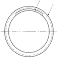
Fig. 1 is the pipeline configuration schematic diagram that the utility model provides;
Fig. 2 is the pipeline stiffening rib welding line structure schematic diagram that the utility model provides;
Fig. 3 is the material structure schematic diagram of the pipeline that provides of the utility model;
Fig. 4 A is the prefabricated flange side view of the pipeline that provides of the utility model;
Fig. 4 B is the prefabricated flange plan view of the pipeline that provides of the utility model;
Fig. 4 C is the rapid pipe joint side view of the pipeline that provides of the utility model;
Fig. 4 D is the rapid pipe joint plan view of the pipeline that provides of the utility model.
Embodiment
Below in conjunction with drawings and Examples, the utility model is described in further detail.
The utility model provides a kind of bimetal composite gas extraction pipeline of band coating, and caliber is 40~2000mm, and as shown in Figure 1, described pipe surface has spiral reinforcing rod 1 structure, is the overlapping part in adjacent two sections steel strip winding processes.The width of described stiffening rib 1 is 4~36mm, and pipeline pitch is 137~600mm.Described pipeline is formed by bimetal composite steel band spiral winding interlock welding.Pipeline material comprises three-decker, be respectively stainless steel lining A, carbon steel layer B and coating C by inwall to outer wall, as shown in Figure 3, the thickness of described stainless steel lining A and carbon steel layer B and be 0.5~4mm, stainless steel lining A thickness be less than described thickness and 5~40%, described coating C thickness is 0.1~0.6mm.Described coating C the selection of material is paint, polyethylene powders, epoxy powder, polyether series, polyureas or glass fibre reinforced plastics etc.Be welded with prefabricated flange plate at the two ends of described pipeline and see that Fig. 4 A, Fig. 4 B or rapid pipe joint is shown in Fig. 4 C, Fig. 4 D, for the connection between pipeline.
The pipeline that the utility model provides prepares by the following method:
The first step, choose the compound structural steel band of carbon steel and stainless steel, using described stainless steel as inner-walls of duct; Carbon steel is as outer wall.Stainless steel thickness is less than 5~40% of described thickness of strips.Described thickness of strips is 0.5~4mm.
Second step, ribbon spiral is wound around the interlock welding and forms pipeline.
Ribbon spiral is wound around the interlock welding and forms pipeline.In spiral winding interlock welding process, stainless steel lining is as inner wall layer, steel band edge carries out the flange processing, adjacent two sections steel bands are overlapped at the flange place, as shown in Figure 2, after steel band flange overlap joint, at pipeline outer wall 4, welded, inwall 5 does not weld, and weld seam is on the carbon steel material surface of adjacent two sections steel bands.The pipeline configuration formed like this, make this pipeline in the coal mine gas course of conveying, because geology changes, and the displacement of generation or stretching, occlusion portion is by extending the length that discharges 3%-6%, and the while guarantees that again methane gas do not reveal.This characteristic has the elongation property of high polymer plastic pipe simultaneously, is also that common steel tube is not available, and this feature is very important for Safety of Coal Mine Production.For example: the total length of a pipe-line system is 1000m, so its reply geology sedimentation and the variable that produces just has the length of 30m-60m to discharge.
The pitch of described spiral winding is 137~600mm.
The diameter of formed pipeline is 40~2000mm.
The width of described flange overlap joint is 4~36mm, and lap-joint forms the reinforcing rib structure with four stiffness layer thickness.This stiffening rib is realized the connection between adjacent steel band on the one hand, plays on the other hand the effect of supporting the steel band pipeline, also can make described pipeline have the performance of anti-negative pressure.
The 3rd step, carry out the derusting by sandblasting processing to pipeline outer wall 4; Then carry out embossing at described outer wall (comprising stiffening rib 1 surface that the flange weld seam forms), increase the roughness of pipeline outer wall.
The 4th step, weld respectively prefabricated flange plate or prefabricated rapid pipe joint at the body two ends of pipeline.
See accompanying drawing 4A~Fig. 4 D, described rapid pipe joint 3 or prefabricated flange plate 2 inwalls are provided with spiral chute 6, for coordinating with the stiffening rib 1 of tube wall 4, guarantee rapid pipe joint 3 or the inwall of prefabricated flange plate 2 and combining closely of pipeline outer wall, then in rapid pipe joint 3 or prefabricated flange plate 2, with 4 contacting points, the pipeline outside, carry out girth welding.
Described rapid pipe joint 3 can be Snap ring structure, and described Snap ring structure refers at the two ends of pipeline fixed groove 7 structural members, during connection, snap ring is stuck in groove 7, and fastening snap ring, realize the connection of two pipelines.
The 5th step, surperficial applying coating.
Described cladding material is paint, polyethylene powders, epoxy powder, polyether series, polyureas or glass fibre reinforced plastics etc.Adopt the form applied, final coating thickness is 0.1~0.6mm.Apply the PE temperature and be controlled at 160~200 degrees centigrade, apply EP and be controlled at 140~160 degrees centigrade of temperature, other get final product according to common process.
Claims (4)
1. the bimetal composite gas extraction pipeline of a coating, it is characterized in that: described gas drainage pipeline selects the interlock of bimetal composite steel band spiral winding to be welded, described bimetal is carbon steel and stainless steel, the caliber that forms pipeline is 40~2000mm, described pipe surface has the spiral reinforcing rod structure, is the overlapping part in adjacent two sections steel strip winding processes; The width of described stiffening rib is 4~36mm, and pipeline pitch is 137~600mm; The structural pipe wall of pipeline comprises three layers, be respectively stainless steel lining, carbon steel layer and coating by inwall to outer wall, the thickness of described stainless steel lining and carbon steel layer and be 0.5~4mm, stainless steel lining thickness be less than described thickness and 5~40%, described coating thickness is 0.1~0.6mm.
2. the bimetal composite gas extraction pipeline of a kind of coating according to claim 1, it is characterized in that: described coating chosen material is paint, polyethylene powders, epoxy powder, polyether series, polyureas or glass fibre reinforced plastics.
3. the bimetal composite gas extraction pipeline of a kind of coating according to claim 1, is characterized in that: at the two ends of described pipeline, be welded with prefabricated flange plate or rapid pipe joint; Inboard in described prefabricated flange plate and rapid pipe joint is provided with spiral chute, with the stiffening rib of pipeline outer wall, coordinates rear girth welding to be connected.
4. the bimetal composite gas extraction pipeline of a kind of coating according to claim 1, it is characterized in that: described pipeline outer wall carbon steel layer surface has embossing.
Priority Applications (1)
| Application Number | Priority Date | Filing Date | Title |
|---|---|---|---|
| CN2013203908620U CN203336070U (en) | 2013-07-02 | 2013-07-02 | Bi-metal composite gas drainage pipeline with coating |
Applications Claiming Priority (1)
| Application Number | Priority Date | Filing Date | Title |
|---|---|---|---|
| CN2013203908620U CN203336070U (en) | 2013-07-02 | 2013-07-02 | Bi-metal composite gas drainage pipeline with coating |
Publications (1)
| Publication Number | Publication Date |
|---|---|
| CN203336070U true CN203336070U (en) | 2013-12-11 |
Family
ID=49704746
Family Applications (1)
| Application Number | Title | Priority Date | Filing Date |
|---|---|---|---|
| CN2013203908620U Expired - Fee Related CN203336070U (en) | 2013-07-02 | 2013-07-02 | Bi-metal composite gas drainage pipeline with coating |
Country Status (1)
| Country | Link |
|---|---|
| CN (1) | CN203336070U (en) |
Cited By (3)
| Publication number | Priority date | Publication date | Assignee | Title |
|---|---|---|---|---|
| CN103343844A (en) * | 2013-07-02 | 2013-10-09 | 马明振 | Duplex-metal composite gas drainage pipeline with coating and manufacturing method thereof |
| CN103727318A (en) * | 2013-12-23 | 2014-04-16 | 山西中通管业有限公司 | Special stainless steel coal-mine gas drainage pipe with reinforcing rib |
| CN115171518A (en) * | 2022-03-29 | 2022-10-11 | 浙江广厦建设职业技术大学 | Art and craft fingerpost integrated with solar energy storage module |
-
2013
- 2013-07-02 CN CN2013203908620U patent/CN203336070U/en not_active Expired - Fee Related
Cited By (4)
| Publication number | Priority date | Publication date | Assignee | Title |
|---|---|---|---|---|
| CN103343844A (en) * | 2013-07-02 | 2013-10-09 | 马明振 | Duplex-metal composite gas drainage pipeline with coating and manufacturing method thereof |
| CN103343844B (en) * | 2013-07-02 | 2016-01-20 | 马明振 | A kind of bimetal composite gas extraction pipeline of coating and manufacture method thereof |
| CN103727318A (en) * | 2013-12-23 | 2014-04-16 | 山西中通管业有限公司 | Special stainless steel coal-mine gas drainage pipe with reinforcing rib |
| CN115171518A (en) * | 2022-03-29 | 2022-10-11 | 浙江广厦建设职业技术大学 | Art and craft fingerpost integrated with solar energy storage module |
Similar Documents
| Publication | Publication Date | Title |
|---|---|---|
| CN103343844B (en) | A kind of bimetal composite gas extraction pipeline of coating and manufacture method thereof | |
| CN103557381B (en) | Strengthened steel pipe with rib spirally wound as well as special equipment and method for manufacturing preparing strengthened steel pipe | |
| CN103574187B (en) | Flexible superhigh molecular polyethylene compound pipe and preparation method thereof and production system | |
| CN102359668A (en) | Flame retardant and antistatic steel mesh skeleton polyethylene composite pipe for mining and manufacturing method thereof | |
| CN101907206B (en) | Steel-belt occlusion welding plastic-coated composite pipe and preparation method thereof | |
| CN103195988B (en) | Mineral methane gas drainage pipe and production method thereof | |
| CN203336070U (en) | Bi-metal composite gas drainage pipeline with coating | |
| CN103672197B (en) | Multi-layer co-extruded mining conveying pipe of ultra-high molecular weight polyethylene and preparation method thereof | |
| CN205383351U (en) | Spiral winding muscle reinforcing tubular metal resonator structure | |
| CN208546625U (en) | A kind of Duel-channel steel-plastic complex pipe | |
| CN102927383A (en) | Tooth-shaped-section pressure-resisting armor layer for composite hoses | |
| CN203823259U (en) | Plastic-coated pressure-resistant pipe with reinforcing ribs | |
| CN203549167U (en) | Steel-belt-reinforced spiral corrugated pipe | |
| CN203585598U (en) | Mineral methane gas drainage pipe | |
| CN203571251U (en) | Spiral winding rib enhancing steel tube | |
| CN200975562Y (en) | Glass fibre reinforced plastic composite pipeline | |
| CN215172889U (en) | Steel fiber soaks moulds compound pipe of fire-retardant antistatic polyethylene of area reinforcing | |
| CN207406937U (en) | A kind of antistatic steel wire mesh frame polyethylene compound pipe of highly effective flame-retardant | |
| CN202532040U (en) | A connecting structure for steel reinforced spirally wound polyethylene pipes used in underground coal mines | |
| CN201672172U (en) | Steel belt occluding welding plastic coated composite tube | |
| CN204083555U (en) | Steel wire mesh frame polyethylene compound pipe | |
| CN103727318A (en) | Special stainless steel coal-mine gas drainage pipe with reinforcing rib | |
| CN202578753U (en) | Gas draining pipe for coal mining | |
| CN203442351U (en) | Spiral-rib reinforced stainless steel gas pipe | |
| CN217422447U (en) | Welding type steel skeleton structure polyolefin composite pipe for underground water supply and drainage of coal mine |
Legal Events
| Date | Code | Title | Description |
|---|---|---|---|
| C14 | Grant of patent or utility model | ||
| GR01 | Patent grant | ||
| CX01 | Expiry of patent term |
Granted publication date: 20131211 |
|
| CX01 | Expiry of patent term | ||
| CU01 | Correction of utility model |
Correction item: Termination upon expiration of patent Correct: Revocation of Patent Expiration and Termination False: Expiration and Termination of 39 Volume 2901 Patent on July 18, 2023 Number: 29-01 Volume: 39 |
|
| CU01 | Correction of utility model | ||
| CF01 | Termination of patent right due to non-payment of annual fee |
Granted publication date: 20131211 |
|
| CF01 | Termination of patent right due to non-payment of annual fee |