CN203553023U - Grounding switch structure of load switch - Google Patents
Grounding switch structure of load switch Download PDFInfo
- Publication number
- CN203553023U CN203553023U CN201320754597.XU CN201320754597U CN203553023U CN 203553023 U CN203553023 U CN 203553023U CN 201320754597 U CN201320754597 U CN 201320754597U CN 203553023 U CN203553023 U CN 203553023U
- Authority
- CN
- China
- Prior art keywords
- earthing
- catch
- grounding
- load switch
- conduction
- Prior art date
- Legal status (The legal status is an assumption and is not a legal conclusion. Google has not performed a legal analysis and makes no representation as to the accuracy of the status listed.)
- Expired - Fee Related
Links
- 239000002184 metal Substances 0.000 claims description 13
- 229910052751 metal Inorganic materials 0.000 claims description 13
- 230000007423 decrease Effects 0.000 claims description 3
- 230000000149 penetrating effect Effects 0.000 claims description 3
- 238000003466 welding Methods 0.000 claims description 3
- 230000000903 blocking effect Effects 0.000 abstract 5
- 230000000712 assembly Effects 0.000 abstract 1
- 238000000429 assembly Methods 0.000 abstract 1
- 150000002500 ions Chemical class 0.000 abstract 1
- RYGMFSIKBFXOCR-UHFFFAOYSA-N Copper Chemical compound [Cu] RYGMFSIKBFXOCR-UHFFFAOYSA-N 0.000 description 3
- 229910052802 copper Inorganic materials 0.000 description 3
- 239000010949 copper Substances 0.000 description 3
- 238000000034 method Methods 0.000 description 3
- 230000005540 biological transmission Effects 0.000 description 2
- 230000015572 biosynthetic process Effects 0.000 description 2
- 230000005611 electricity Effects 0.000 description 2
- 208000027418 Wounds and injury Diseases 0.000 description 1
- 230000006378 damage Effects 0.000 description 1
- 230000007812 deficiency Effects 0.000 description 1
- 230000000694 effects Effects 0.000 description 1
- 208000014674 injury Diseases 0.000 description 1
- 238000012423 maintenance Methods 0.000 description 1
- 238000012986 modification Methods 0.000 description 1
- 230000004048 modification Effects 0.000 description 1
- XLYOFNOQVPJJNP-UHFFFAOYSA-N water Substances O XLYOFNOQVPJJNP-UHFFFAOYSA-N 0.000 description 1
Images


Landscapes
- Switch Cases, Indication, And Locking (AREA)
Abstract
The utility model discloses a grounding switch structure of a load switch. The grounding switch comprises a grounding switch body and three conductive assemblies; each conductive assembly comprises a sensor fixed on the grounding switch body and a voltage-sharing cover mounted on the sensor; two ends of the grounding switch body are both provided with a conductive supporting plate; the grounding switch further comprises a grounding frame; one side of the grounding frame is provided with a plurality of blocking sheet pairs; each blocking sheet pair is matched with the voltage-sharing cover, such that the voltage-sharing cover can be embedded in the blocking sheet pair; and the grounding frame is hinged on the conductive supporting plates at the two ends of the grounding switch body, and therefore, the voltage-sharing covers can be connected with the grounding switch body. According to the grounding switch structure of the load switch of the utility model, the grounding frame is hinged with the grounding switch body, such that a structure that rotates with hinging points as fulcrums can be formed; when the grounding switch body rotates to the blocking sheet pairs, the voltage-sharing covers at corresponding positions are made to be clamped in the blocking sheet pairs, and therefore, grounding communication can be realized; residual electric ions of the voltage-sharing covers are led into the ground, and therefore, safety in use can be ensured; and a requirement for 36kV can be satisfied.
Description
Technical field
The utility model relates to the earthing structure on a kind of on-load switch, by International Patent Classification (IPC) (IPC), divides and belongs to electric elements technical field.
Background technology
Earthed switch is the electrical equipment that plays ground protection effect for switch cupboard; can effectively prevent the accident of getting an electric shock because of residual voltage or because of the maintenance process personal injury that incoming call occurs suddenly; be widely used in high-voltage switch gear cabinet equipment; only have in the market 12kV to follow 24kV's; also do not have to reach and meet 36kV's; this has hindered power industry and has further improved power transmission electric network voltage security grade, thereby has caused electric power safety problem in transmission of electricity process.And existing earthed switch can not be realized fastening clamping formation with grading shield, thereby reduce its serviceability, and then reduce the fail safe in use of whole equipment.
Thus, the inventor considers the earthing structure on existing on-load switch to improve, and this case produces thus.
Utility model content
For the deficiencies in the prior art, the utility model provides the structure of the earthing on a kind of on-load switch, this earthing structure is ground connection catch and grading shield good contact when grounding switch closes a floodgate, thereby the residual voltage in switch loop is introduced to the earth, thereby guarantee operating personnel's personal safety.
For achieving the above object, the utility model is achieved through the following technical solutions:
Earthing structure on a kind of on-load switch, this earthing structure is installed in switch cabinet and coordinates with on-load switch to realize electron ion is directed into the earth, this earthing comprises earthing body and three conduction groups, described each conduction group comprises and is fixed on the transducer on earthing body and is installed on the grading shield on transducer, and described earthing body two ends all have conduction support plate; Described earthing also comprises a grounding frame, described grounding frame one side has multiple catch pair, described each catch pair and grading shield coordinate that corresponding grading shield is embedded in to this catch is internal, this grounding frame is articulated with on the conduction support plate at earthing body two ends, and then realizes grading shield and be connected with earthing body.
Further, the right quantity of described multiple catch is three, and arranges respectively at three conduction groups are corresponding, and each catch is to all linking into an integrated entity by welding and grounding frame.
Further, described each catch is rectangular box-like to being that a metallic conduction sheet is bent to form its two ends to same direction, and the grading shield of correspondence position is held on to its inside, on the right bare terminal end of this catch, is provided with multiple clampings projections.
Further, described multiple clamping projection is arranged at catch to bare terminal end inner side, the protruding height of multiple clampings successively decreases and arranges to its inside bare terminal end along this catch, form stepped interface arrangment, the protruding quantity of described clamping is 3-5, each clamping protruding all with catch to the formula structure that links into an integrated entity.
Further, described grounding frame comprises the articulated section at integrated frame shape support and support two ends, and each articulated section is all tabular and described conduction support plate, is connected and realizes electron ion conducting.
Further, described transducer is the pole that is built-in with current sensor, and this transducer is that taper is tower-like, and the tip of each transducer is fixed with a grading shield.
Further, described grading shield is conductive tube penetrating Shang Xia.
Further, described conduction support plate is that the curved metal conducting strip on earthing body is fixed in one end.
Further, the tapered setting of described earthing body, it comprises the conductive metal sheet of two, and these two conductive metal sheet one end connect and mutually support the earthing conductive plate that forms integral type, and described each conduction group is all fixed on a conductive metal sheet.
The structure that the utility model utilizes grounding frame and the hinged formation of earthing body to rotate take interface point as fulcrum, wherein rotate to catch the grading shield of correspondence position is placed in to its inside, and then be grounded connection, residual electricity ion water conservancy diversion on grading shield is entered to the earth, and then guarantee the fail safe in use, and can reach the requirement that meets 36kV.
Accompanying drawing explanation
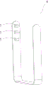
Fig. 1 is the utility model separating brake structural representation in an embodiment;
Fig. 2 is the utility model structural representation that closes a floodgate in an embodiment;
Fig. 3 be in the utility model catch to structural representation.
Embodiment
Below in conjunction with accompanying drawing, the utility model is described in further detail:
Embodiment: refer to shown in Fig. 1 to Fig. 3, earthing structure on a kind of on-load switch, this earthing structure is installed in switch cabinet and coordinates with on-load switch to realize electron ion is directed into the earth, this earthing comprises earthing body 1 and three conduction groups 2, described each conduction group 2 comprises the transducer 21 being fixed on earthing body 1 and is installed on the grading shield 22 on transducer 21, and described earthing body 1 two ends all have conduction support plate 11; Described earthing also comprises a grounding frame 3, described grounding frame 3 one sides have multiple catch to 4, described each catch coordinates corresponding grading shield 22 is embedded in to this catch in 4 with grading shield 22 4, this grounding frame 3 is articulated with on the conduction support plate 11 at earthing body 4 two ends, and then realizes grading shield 22 and be connected with earthing body 1.
Refer to shown in Fig. 1 to Fig. 3, described multiple catch are three to 4 quantity, and arrange respectively at three conduction groups 2 are corresponding, and each catch all links into an integrated entity by welding and grounding frame 3 to 4; It is rectangular box-like that described each catch is to 4 that a metallic conduction sheet is bent to form its two ends to same direction, and the grading shield of correspondence position is held on to its inside, on the right bare terminal end of this catch, is provided with multiple clampings projections 5; Described multiple clamping projection 5 is arranged at catch to 4 bare terminal end inner sides, the height of multiple clamping projections 5 successively decreases and arranges to its inside bare terminal end along this catch, form stepped interface arrangment, the projection of clamping described in the present embodiment 5 is three,, each clamping projection 5 all with catch to the 4 formula structures that link into an integrated entity.
Refer to shown in Fig. 1 to Fig. 3, described grounding frame 3 comprises the articulated section 32 at integrated frame shape support 31 and support two ends, and each articulated section 32 is all tabular and described conduction support plate 11, is connected and realizes electron ion conducting, and this grounding frame 31 is copper framework.
Refer to shown in Fig. 1 to Fig. 3, described transducer 21 is for being built-in with the pole of current sensor, and this transducer 21 is tower-like for taper, and the tip of each transducer 21 is fixed with a grading shield 22, described grading shield 22 is conductive tube penetrating Shang Xia, and this conductive tube is copper conductive tube.
Refer to shown in Fig. 1 to Fig. 3, described conduction support plate 11 is fixed on the curved metal conducting strip on earthing body 1 for one end, and curved metal conducting strip is copper sheet.
Refer to shown in Fig. 1 to Fig. 3, the tapered setting of described earthing body 1, it comprises the conductive metal sheet 13 of two, and these two conductive metal sheets, 13 one end connect and mutually support the earthing conductive plate that forms integral type, and described each conduction group 2 is all fixed on a conductive metal sheet 13.
The utility model cannot operational grounding switch when on-load switch closes a floodgate, only having in the time of on-load switch separating brake just can operational grounding switch, ground connection catch and grading shield good contact when grounding switch closes a floodgate, thereby the residual voltage in switch loop is introduced to the earth, thereby guarantee operating personnel's personal safety.
Above record, only, for utilizing the embodiment of this origination techniques content, modification, variation that any those skilled in the art use this creation to do, all belong to the scope of the claims that this creation is advocated, and be not limited to those disclosed embodiments.
Claims (9)
1. the earthing structure on an on-load switch, this earthing structure is installed in switch cabinet and coordinates with on-load switch to realize electron ion is directed into the earth, it is characterized in that: this earthing comprises earthing body and three conduction groups, described each conduction group comprises and is fixed on the transducer on earthing body and is installed on the grading shield on transducer, and described earthing body two ends all have conduction support plate; Described earthing also comprises a grounding frame, described grounding frame one side has multiple catch pair, described each catch pair and grading shield coordinate that corresponding grading shield is embedded in to this catch is internal, this grounding frame is articulated with on the conduction support plate at earthing body two ends, and then realizes grading shield and be connected with earthing body.
2. the earthing structure on a kind of on-load switch according to claim 1, is characterized in that: the right quantity of described multiple catch is three, and arranges respectively at three conduction groups are corresponding, and each catch is to all linking into an integrated entity by welding and grounding frame.
3. the earthing structure on a kind of on-load switch according to claim 2, it is characterized in that: described each catch is to being that a metallic conduction sheet is bent to form rectangular box-like by its two ends to same direction, the grading shield of correspondence position is held on to its inside, on the right bare terminal end of this catch, is provided with multiple clampings projections.
4. the earthing structure on a kind of on-load switch according to claim 3, it is characterized in that: described multiple clamping projections are arranged at catch to bare terminal end inner side, the protruding height of multiple clampings successively decreases and arranges to its inside bare terminal end along this catch, forms stepped interface arrangment.
5. the earthing structure on a kind of on-load switch according to claim 1 and 2, it is characterized in that: described grounding frame comprises the articulated section at integrated frame shape support and support two ends, and each articulated section is all tabular and described conduction support plate, is connected and realizes electron ion conducting.
6. the earthing structure on a kind of on-load switch according to claim 1, is characterized in that: described transducer is the pole that is built-in with current sensor, this transducer is that taper is tower-like, and the tip of each transducer is fixed with a grading shield.
7. according to the earthing structure on a kind of on-load switch described in claim 1 or 6, it is characterized in that: described grading shield is conductive tube penetrating Shang Xia.
8. the earthing structure on a kind of on-load switch according to claim 1, is characterized in that: described conduction support plate is that the curved metal conducting strip on earthing body is fixed in one end.
9. according to the earthing structure on a kind of on-load switch described in claim 1 or 8, it is characterized in that: the tapered setting of described earthing body, it comprises the conductive metal sheet of two, these two conductive metal sheet one end connect and mutually support the earthing conductive plate that forms integral type, and described each conduction group is all fixed on a conductive metal sheet.
Priority Applications (1)
| Application Number | Priority Date | Filing Date | Title |
|---|---|---|---|
| CN201320754597.XU CN203553023U (en) | 2013-11-26 | 2013-11-26 | Grounding switch structure of load switch |
Applications Claiming Priority (1)
| Application Number | Priority Date | Filing Date | Title |
|---|---|---|---|
| CN201320754597.XU CN203553023U (en) | 2013-11-26 | 2013-11-26 | Grounding switch structure of load switch |
Publications (1)
| Publication Number | Publication Date |
|---|---|
| CN203553023U true CN203553023U (en) | 2014-04-16 |
Family
ID=50471104
Family Applications (1)
| Application Number | Title | Priority Date | Filing Date |
|---|---|---|---|
| CN201320754597.XU Expired - Fee Related CN203553023U (en) | 2013-11-26 | 2013-11-26 | Grounding switch structure of load switch |
Country Status (1)
| Country | Link |
|---|---|
| CN (1) | CN203553023U (en) |
Cited By (1)
| Publication number | Priority date | Publication date | Assignee | Title |
|---|---|---|---|---|
| CN110838423A (en) * | 2018-08-16 | 2020-02-25 | 铁路电力系统股份有限公司 | Voltage limiting device |
-
2013
- 2013-11-26 CN CN201320754597.XU patent/CN203553023U/en not_active Expired - Fee Related
Cited By (2)
| Publication number | Priority date | Publication date | Assignee | Title |
|---|---|---|---|---|
| CN110838423A (en) * | 2018-08-16 | 2020-02-25 | 铁路电力系统股份有限公司 | Voltage limiting device |
| US11417488B2 (en) | 2018-08-16 | 2022-08-16 | Rail Power Systems Gmbh | Voltage limiting device |
Similar Documents
| Publication | Publication Date | Title |
|---|---|---|
| CN204885734U (en) | Box -type substation box body ground connection protection device | |
| CN202888523U (en) | Whole shielding metal armored cable connecting plug | |
| CN203553023U (en) | Grounding switch structure of load switch | |
| CN209658439U (en) | A kind of plug-in ground line with electrical verification warning function | |
| CN202772486U (en) | Solid insulation switch device and assembly thereof | |
| CN202068167U (en) | 1-in 2-out junction box for high voltage cable | |
| CN202710688U (en) | Probe device for detecting arc lights | |
| CN210296210U (en) | An outdoor high voltage isolation switch | |
| CN104707835A (en) | 800 kV enclosed-type assembled switch gear busbar device metal particle trapping and eliminating device | |
| CN212010618U (en) | Power electrical transformer with lightning protection function | |
| CN209641511U (en) | A kind of current transformer preventing suspended voltage | |
| CN216487566U (en) | A Filter Capacitor Reactor With Durable Compression Structure | |
| CN202712553U (en) | Shielded type switch cabinet upper outgoing bus connector | |
| CN202940459U (en) | Lightning arrester used in extra-high voltage alternating-current electric transmission line | |
| CN209448400U (en) | It is touch separation type power cable connecting piece used | |
| CN221080920U (en) | Grounding device of overvoltage protector | |
| CN103997867A (en) | Static discharge protection shell used for industrial Ethernet switch | |
| CN206673547U (en) | A kind of new 6 10 kilovolts of overhead lines double-rod structure for installing lightning arrester | |
| CN203851392U (en) | Electronic-static discharge protective shell for use in industrial Ethernet switch | |
| CN108808603A (en) | 35kV switchgear bus casings | |
| CN105261517A (en) | Seal pole for PT cabinet | |
| CN203243008U (en) | Hanging 35kV double-contact lightning arrester | |
| CN202549516U (en) | Suspension type line arrester for alternating current system | |
| CN219677578U (en) | Outdoor electric equipment grounding device with contact voltage protection function | |
| CN203859074U (en) | Shell structure of electric leakage circuit breaker |
Legal Events
| Date | Code | Title | Description |
|---|---|---|---|
| C14 | Grant of patent or utility model | ||
| GR01 | Patent grant | ||
| CF01 | Termination of patent right due to non-payment of annual fee | ||
| CF01 | Termination of patent right due to non-payment of annual fee |
Granted publication date: 20140416 Termination date: 20201126 |