CN2040877U - Bicycle with automatic stress applying device - Google Patents
Bicycle with automatic stress applying device Download PDFInfo
- Publication number
- CN2040877U CN2040877U CN88212625U CN88212625U CN2040877U CN 2040877 U CN2040877 U CN 2040877U CN 88212625 U CN88212625 U CN 88212625U CN 88212625 U CN88212625 U CN 88212625U CN 2040877 U CN2040877 U CN 2040877U
- Authority
- CN
- China
- Prior art keywords
- bicycle
- axle
- sprocket wheel
- design
- automatic driving
- Prior art date
- Legal status (The legal status is an assumption and is not a legal conclusion. Google has not performed a legal analysis and makes no representation as to the accuracy of the status listed.)
- Pending
Links
- 238000004146 energy storage Methods 0.000 abstract description 6
- 238000005096 rolling process Methods 0.000 abstract 1
- 238000000034 method Methods 0.000 description 2
- 208000019901 Anxiety disease Diseases 0.000 description 1
- 235000008331 Pinus X rigitaeda Nutrition 0.000 description 1
- 235000011613 Pinus brutia Nutrition 0.000 description 1
- 241000018646 Pinus brutia Species 0.000 description 1
- 230000001133 acceleration Effects 0.000 description 1
- 230000036506 anxiety Effects 0.000 description 1
- 230000005540 biological transmission Effects 0.000 description 1
- 230000001141 propulsive effect Effects 0.000 description 1
Images


Landscapes
- Arrangement Or Mounting Of Propulsion Units For Vehicles (AREA)
Abstract
The bicycle with an automatic stress applying device of the utility model belongs to a walking tool attached with an automatic stress applying device. The utility model can store the energy of the glide force by an energy storage mechanism when the bicycle goes downhill; the stored energy is released to increase the bicycle propulsion when the bicycle goes uphill or is ridden on the level road, so as to achieve the purpose of saving labor. An energy storage mechanism and an energy transfer system are arranged on the existing brake block type common bicycle, comprising a rear left flywheel (7), chain wheels (9) (12) and a reverse flywheel (8). The bicycle with an automatic stress applying device can use the residual energy in running, and can generally adapt to rolling area and mountain area.
Description
The utility model relates to a kind of bicycle with the automatic driving-force adding device.
At present, popular bicycle has spark ignition engine bicycle, storage battery bicycle, common bicycle or the like on the market.Though preceding two kinds faster than common car, need expend gasoline, battery etc., except that the raw MAT'L anxiety, refuel, charging, both required great effort trouble again, and cost is higher; And ordinary bicycle is unpowered, extremely requires great effort during upward slope.
The purpose of this utility model is to design a kind of assistor of human-saving to ordinary bicycle, for people provide a kind of bicycle with the automatic driving-force adding device, can make the automatic energy storage of bicycle, again can the automatic release energy, promote the strength that bicycle advances to increase.
Technical solution of the present utility model is: design a stored energy mechanism, the sliding force during with the bicycle descending stores, and when upward slope or level road walking, will store on demand and can come out by automatic release, advances to promote bicycle, reaches the labour-saving purpose.This bicycle is on the basis of existing brake shoe formula brake bicycle, designs a stored energy mechanism (2), with support (3) stored energy mechanism is fixed on the cycle frame (1); In the design of the left side of backshaft skin flywheel (7) is arranged again, at the left side of axis design one reverse flywheel (8), link up with the sprocket wheel (9) of chain, link up with the sprocket wheel (12) and the reverse flywheel (8) of chain again stored energy mechanism with flywheel (7) and stored energy mechanism.Mix cable brake (4) again, just can realize automatic energy storage and automatic release energy, with reach bicycle advance in the purpose of automatic driving-force adding.Accompanying drawing has been described an embodiment of this case, is further described in detail below in conjunction with accompanying drawing.As shown in Figure 3, stored energy mechanism (2) comprises axle (10), belt disc spring (being clockwork spring) (13), sprocket wheel (12) and end face clutch (11), this power-transfer clutch is made up of last item (15), surface bearing (16), zygote (14), spring (22) and sprocket wheel (9).Sprocket wheel (12) is designed to boxlike, interior dress belt disc spring (being clockwork spring) (13), and an end of disc spring and axle (10) are connected and fixed, and the inner casing of the other end and boxlike sprocket wheel (12) is connected and fixed (see figure 4), and sprocket wheel (12) is a bearing fit with axle; Sprocket wheel (9) and zygote (14) form tooth embedding clutch, and it is bearing fit with axle that middle design has spring (22), sprocket wheel (9), and zygote (14) is that spline links with axle; Last item (15) forms flush fit with an end of surface bearing.Whole stored energy mechanism is supported on the centre of support (3) by axle.Oppositely the inner hole thread of flywheel (8) is designed to minus thread, and the direction of the ratchet of its overcoat and two ratchets is opposite with freewheel.
The energy storage of this automatic driving-force adding device and to release exergic process as follows: when level road is walked, bicycle rear drives flywheel (7) rotation, flywheel (7) drives sprocket wheel (9) idle running by chain, (see figure 3) hand operation brake cable (4) during descending, affect last item (15), by surface bearing (16), make zygote (14) overcome the elastic force of spring (22) and move to right, mesh with sprocket wheel (9).At this moment, axle (10) rotation (see figure 4), the heart portion that drives belt disc spring (13) rotates, and promptly tightens disc spring (13), reaches the energy storage purpose.At this moment, as previously mentioned, both feet control pedal keeps original position motionless, tightens otherwise influence disc spring.After disc spring all tightened, zygote (14) skidded automatically, unclamps rim brake immediately, and it is motionless that both feet still keep, and it is motionless promptly to control sprocket wheel (12).During upward slope, the pine both feet discharge the accumulator energy slightly.Sprocket wheel this moment (12) optionally rotates, drive reverse flywheel (8), power is passed to floral disc (5), the driving trailing wheel advances, and when the gradient was especially big, both feet simultaneously to pedal, making manpower and storing the power that discharges is applied on the drive wheel simultaneously, advance with accelerating vehicle, when axle (10) is rotated, drive ratchet (17) and rotate (see figure 5).Ratchet (17) is braked by ratchet (20).Ratchet (20) is controlled by leaf spring (21).This overlaps ratchet device, has guaranteed that under the situation that zygote (14) is thrown off, axle (10) can not reversed yet after expiring on the disc spring.Axle (10) is controlled its axial motion with spring collar (19) by elastic force trim ring (18) by axle.
The utility model is on probation through advanced development, illustrated bicycle in the process of moving can be reasonably stored energy automatically, automatic release energy as required again is to increase propulsive effort, the speed of advance of acceleration bicycle.This bicycle that has the automatic driving-force adding device is particularly suitable for hills area and mountain area and uses.
Description of drawings:
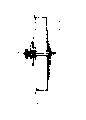
Fig. 1 has the transmission scheme drawing of the bicycle of automatic driving-force adding device.
The birds-eye view of Fig. 2: Fig. 1
Fig. 3: stored energy mechanism scheme drawing (Fig. 1 amplifies relatively)
The A-A of Fig. 4: Fig. 3 is to view
Fig. 5, the B of Fig. 3 is to (part) view
Claims (5)
1, a kind of bicycle that has the automatic driving-force adding device,
Feature of the present utility model is that design has a stored energy mechanism (2), this mechanism is bearing on the support (3) by an axle (10), and support (3) is fixed on the cycle frame (1), and design has flywheel (7) on the left of backshaft skin, the design of axis left end has reverse flywheel (8), stored energy mechanism (2) is gone up design sprocket wheel (12), and the left end of axle (10) designs end face clutch (11), and the cable brake (4) of control clutch is arranged.
2, by the described bicycle that has the automatic driving-force adding device of claim 1, it is characterized in that stored energy mechanism (2) comprises axle (10), belt disc spring (13), sprocket wheel (12), one end and the axle of its disc spring are connected and fixed, the inner casing of the other end and boxlike sprocket wheel (12) is connected and fixed, and sprocket wheel (12) is a bearing fit with axle.
3, by the described bicycle that has the automatic driving-force adding device of claim 1, it is characterized in that end face clutch (11) is made up of last item (15), surface bearing (16), zygote (14), spring (22) and sprocket wheel (9), sprocket wheel (9) and zygote form tooth embedding clutch, middle design has spring (22), sprocket wheel (9) is a bearing fit with axle, zygote (14) is that spline links with axle, and last item (15) forms flush fit with surface bearing one end.
4, by the described a kind of bicycle that has the automatic driving-force adding device of claim 1, it is characterized in that the bore design of reverse flywheel (8) becomes minus thread, the direction of the handle ratchet wheel of its overcoat and two ratchets is opposite with freewheel.
5,, it is characterized in that the ratchet device that the design of axle right-hand member has a cover to be made up of ratchet (17), ratchet (20) and leaf spring (21) by claim 1 or 2 described a kind of bicycles that have the automatic driving-force adding device.
Priority Applications (1)
| Application Number | Priority Date | Filing Date | Title |
|---|---|---|---|
| CN88212625U CN2040877U (en) | 1988-05-22 | 1988-05-22 | Bicycle with automatic stress applying device |
Applications Claiming Priority (1)
| Application Number | Priority Date | Filing Date | Title |
|---|---|---|---|
| CN88212625U CN2040877U (en) | 1988-05-22 | 1988-05-22 | Bicycle with automatic stress applying device |
Publications (1)
| Publication Number | Publication Date |
|---|---|
| CN2040877U true CN2040877U (en) | 1989-07-12 |
Family
ID=4845908
Family Applications (1)
| Application Number | Title | Priority Date | Filing Date |
|---|---|---|---|
| CN88212625U Pending CN2040877U (en) | 1988-05-22 | 1988-05-22 | Bicycle with automatic stress applying device |
Country Status (1)
| Country | Link |
|---|---|
| CN (1) | CN2040877U (en) |
Cited By (3)
| Publication number | Priority date | Publication date | Assignee | Title |
|---|---|---|---|---|
| CN1093484C (en) * | 1998-09-05 | 2002-10-30 | 李世球 | Mechanical energy alternative conversion type intermittent power-assisting mechanism for bicycle |
| CN104176189A (en) * | 2013-05-27 | 2014-12-03 | 陈勇 | Novel spring flywheel double-energy-storing balancing bicycle |
| CN108909929A (en) * | 2018-05-29 | 2018-11-30 | 沈江 | A kind of Exercycle |
-
1988
- 1988-05-22 CN CN88212625U patent/CN2040877U/en active Pending
Cited By (4)
| Publication number | Priority date | Publication date | Assignee | Title |
|---|---|---|---|---|
| CN1093484C (en) * | 1998-09-05 | 2002-10-30 | 李世球 | Mechanical energy alternative conversion type intermittent power-assisting mechanism for bicycle |
| CN104176189A (en) * | 2013-05-27 | 2014-12-03 | 陈勇 | Novel spring flywheel double-energy-storing balancing bicycle |
| CN104176189B (en) * | 2013-05-27 | 2017-10-17 | 陈勇 | Novel spring flywheel double-energy storage balance-bicycle |
| CN108909929A (en) * | 2018-05-29 | 2018-11-30 | 沈江 | A kind of Exercycle |
Similar Documents
| Publication | Publication Date | Title |
|---|---|---|
| CN109131700A (en) | A kind of novel energy-storing multi-speed bicycle system | |
| CN101492081A (en) | Remote energy-saving electric bicycle | |
| US20030159869A1 (en) | Motorization of a bicycle with a simple replacement of the bottom bracket | |
| CN2040877U (en) | Bicycle with automatic stress applying device | |
| CN2169593Y (en) | Two speed flying wheel | |
| CN103935450A (en) | Power-assisting bicycle and power assisting method | |
| CN2061548U (en) | Foot-driven inertial force-storing device | |
| CN2205801Y (en) | High-efficient bicycle without spoke | |
| CN2117322U (en) | Bicycle energy accumulating strengthener | |
| CN2305360Y (en) | Mechanical energy storage enforcing device for bicycle | |
| CN2590844Y (en) | Inertial booster bicycle | |
| CN2156124Y (en) | Count-direction pedal driving automatic speed-changing bicycle | |
| CN2063106U (en) | Bicycle with motor-booster for direct driving rear wheel axle | |
| CN2522310Y (en) | Agricultural single-wheel motor vehicle | |
| JPH04108089A (en) | Energy accumulating and releasing bicycle | |
| CN2158839Y (en) | Transmitting device for manual cycle | |
| CN2469239Y (en) | Energy-saving fly wheel for motor cycle | |
| CN2320518Y (en) | Bicycle | |
| CN2261984Y (en) | Spiral power spring bicycle | |
| KR0134993B1 (en) | Rotary power generator | |
| CN2228050Y (en) | Elastic vehicle | |
| JPH0653391U (en) | Electric tricycle using rechargeable storage battery and electric drive | |
| CN2138618Y (en) | Bicycle rear wheel booster | |
| CN2166275Y (en) | Single-sprocket driving double-shaft flywheel | |
| CN2149344Y (en) | Power-saving fast bicycle |
Legal Events
| Date | Code | Title | Description |
|---|---|---|---|
| C06 | Publication | ||
| PB01 | Publication | ||
| C20 | Patent right or utility model deemed to be abandoned or is abandoned | ||
| WD01 | Invention patent application deemed withdrawn after publication |