CN210028811U - Horizontal storage and transfer system - Google Patents
Horizontal storage and transfer system Download PDFInfo
- Publication number
- CN210028811U CN210028811U CN201920584436.8U CN201920584436U CN210028811U CN 210028811 U CN210028811 U CN 210028811U CN 201920584436 U CN201920584436 U CN 201920584436U CN 210028811 U CN210028811 U CN 210028811U
- Authority
- CN
- China
- Prior art keywords
- plates
- goods
- transfer system
- goods shelves
- guide rail
- Prior art date
- Legal status (The legal status is an assumption and is not a legal conclusion. Google has not performed a legal analysis and makes no representation as to the accuracy of the status listed.)
- Active
Links
Images




Landscapes
- Warehouses Or Storage Devices (AREA)
Abstract
The utility model discloses a horizontal storage and transfer system, which comprises a goods shelf, wherein two sides of the goods shelf are correspondingly provided with a left supporting seat and a right supporting seat; goods shelves divide into the multilayer branch goods shelves from top to bottom, be provided with loose pulley assembly in the middle of the inner wall at every layer of both ends that divides goods shelves, every layer of bottom surface that divides goods shelves is provided with loose pulley assembly by one end to the other end also interval, locking Assembly has been arranged along the width direction in the middle of every layer of bottom surface that divides goods shelves, gliding lift platform about being provided with between the supporting seat, lift platform includes that the level is provided with load-bearing platform, load-bearing platform both ends symmetry sets up the lift platen, the interval is provided with the biserial telescoping device on the. The utility model discloses structural style is simple, is applicable to the great packing box of specification and transports, and unmanned intervention, control cost is low, and adaptable rocking, abominable operational environment such as vibrations, and transport the passageway significantly reduce, get goods actuating mechanism significantly reduced, and warehouse storage capacity improves greatly, transports that efficiency is considerable, and system reliability improves greatly.
Description
Technical Field
The utility model relates to a warehouse transit system, concretely relates to horizontal storage transit system.
Background
Present society, warehouse movement system develops fastly, the demand of each trade enlarges day by day, domestic and abroad research to warehouse movement system is more and more ripe, it is also more and more intelligent, but present most warehouse movement system is used for factory building product storage more, this kind of warehouse movement system intelligent degree is higher, it is less to the specification, the goods of light more, work environment is friendly, no vibrations, no wind-load, the space is surplus, the goods storage is mostly the coordinate formula storage, correspond one to one or two storage station in certain floor storage area and get goods actuating mechanism, it is many to get goods actuating mechanism, transfer passage is many. However, under the working conditions of limited space, severe environment, shaking, vibration and the like, such as ships, the warehouse transfer system is not suitable any more.
Disclosure of Invention
An object of the utility model is to overcome prior art not enough, provide a horizontal storage transfer system.
In order to achieve the purpose, the utility model designs a horizontal storage and transportation system, which comprises a goods shelf, wherein two sides of the goods shelf are correspondingly provided with a left supporting seat and a right supporting seat; the goods shelf is divided into multiple layers of goods shelves from top to bottom, a plurality of integral containers are sequentially arranged in each layer of goods shelves from one side to the other side, pulley assemblies are arranged in the middles of the inner walls of the two ends of each layer of goods shelves, the pulley assemblies are also arranged at intervals from one end to the other end of the bottom surface of each layer of goods shelves, the pulley assemblies are all arranged along the width direction of the goods shelves, locking assemblies are arranged in the middles of the bottom surfaces of each layer of goods shelves along the width direction, and each locking assembly comprises locking devices symmetrically arranged on the two sides of each goods shelf;
the lifting platform is arranged between the supporting seats and can slide up and down, the lifting platform comprises a bearing platform which is horizontally arranged, lifting tables are symmetrically arranged at two ends of the bearing platform and can slide back and forth on the supporting seats, and double-row telescopic devices are arranged on the bearing platform at intervals.
Further, the supporting seat comprises a base, right trapezoid plates are symmetrically arranged on the base, guide rail grooves are vertically formed in right-angle edges of the right trapezoid plates and are higher than the right trapezoid plates, guide rails are arranged in the guide rail grooves, vertical plates are arranged between the right trapezoid plates, a plurality of horizontal reinforcing rib plates are arranged between the right trapezoid plates and the vertical plates at intervals from top to bottom, and a motor plate is arranged between the tops of the vertical plates and the wall of each guide rail groove; and a screw rod is arranged on the vertical plate at one end or two ends of the lifting platform and penetrates through the motor plate and the servo motor.
Still further, the bearing platform is provided with a plurality of partition rods, the partition rods divide the bearing platform into a plurality of mounting areas equally, and a motor port is formed in the center of each mounting area.
Still further, the double-row telescopic device comprises mounting seats arranged on two sides of the motor port, slide rails are arranged on the mounting seats, and double-row telescopic arms are arranged on the upper surfaces of the slide rails; the slide rail lateral wall is fixed with flexible motor, flexible motor embedding motor is intraoral.
And the lifting bedplate comprises guide rail sliding plates at two ends and a lead screw sliding plate with a convex middle part, guide rail sliding blocks sliding on the guide rails are symmetrically arranged on the plate surface of the guide rail sliding plate from top to bottom, and a lead screw mounting seat sliding in a matching manner with a nut on the lead screw is arranged on the plate surface of the lead screw sliding plate.
Still further, the guide rail top and the lower part are provided with the dog respectively.
And furthermore, the edges at two ends of the bearing platform and the partition rods are respectively provided with a limiting block, and reinforcing oblique ribs are symmetrically arranged between the bearing platform and the two guide rail sliding plates.
Furthermore, the locking device comprises an installation bottom plate, a connecting plate is arranged in the middle of the installation bottom plate, lock tongues are arranged at two ends of the installation bottom plate, two connecting rods are symmetrically arranged on two side walls of the connecting plate, and the two connecting rods penetrate through the vertically arranged installation supporting seat and are connected with two sides of each lock tongue; the bolt is provided with the connecting rod, the connecting rod is provided with the spring bolt, the cooperation of spring bolt and connecting rod junction one side is provided with the rack bar below, the rack bar is connected with the electric jar of fixing on the erection bracing seat. The locking device is arranged on each layer of goods shelf and is positioned at the position right below the goods boxes at two ends, a certain distance is kept between the pulley block and the telescopic arm in the horizontal direction, the electric cylinder drives the rack to move back and forth to drive the gear to rotate, and the bolt extends or retracts to lock or unlock the locking device with the locking position at the bottom of the goods box.
Furthermore, the length of the pulley assembly is the same as the width of the goods shelf, and the supporting seat is fixed on two sides of the goods shelf through a mounting base at the bottom; and a communication module is arranged on the outer wall of one end of the container.
The utility model also provides a based on above-mentioned horizontal storage transfer system, including following step:
1) the double-row telescopic arm at one side is inserted into the bottom of the container at the layer and is locked with the container through the locking device, meanwhile, the double-row telescopic arm at the other side moves to the waist of the container, the pair of locking devices is unlocked, the double-row telescopic arm at the other side pushes the whole row of containers to one side, and meanwhile, the double-row telescopic arm at one side drags the container to move;
2) when the communication module detects that the next container reaches the position of the previous container, the locking device is used for locking other containers on the layer;
3) when the container continues to move laterally under the action of the double-row telescopic arms until the container is limited right above the lifting platform, the lifting platform drives the container to lift to a target position to wait for taking goods;
4) after the goods are taken, the empty goods box is prepared to return to the warehouse; the lifting platform drives the empty container to lift to a storage returning position, the double-row telescopic arm on one side drives the empty container to be tightly attached to the lower-layer container, the double-row telescopic arm on the other side is inserted into the bottom of other containers on the other side of the lower layer and locked, then the locking position is unlocked, and the double-row telescopic arm on one side drives the empty container to push the other containers on the other side; meanwhile, the double-row telescopic arm at the other side drives other containers to move to the side, after the communication module detects that the whole row of containers moves by one station, the locking device locks the other containers at the layer, and then the empty containers are returned to the warehouse;
5) a container on the other side of the lower layer continuously moves leftwards under the action of the double-row telescopic arms on the other side, and waits for lifting action right above the lifting platform; and the container is lifted to the upper layer under the action of the lifting platform, then the double-row telescopic arm at the other side pushes the container to move right to be tightly attached to the container at the upper layer, the container is locked, and the system is delivered out of the warehouse and put in the warehouse for one cycle.
The utility model has the advantages that:
the utility model discloses structural style is simple, is applicable to the great packing box of specification and transports, and the packing box export is single relatively, and unmanned intervention, control cost is low, and adaptable rocking, abominable operational environment such as vibrations, and the transfer passage significantly reduces, gets goods actuating mechanism significantly reduces, and warehouse storage capacity improves greatly, and transport efficiency is considerable, and system reliability improves greatly.
Drawings
Fig. 1 is a perspective view of the horizontal storage and transfer system of the present invention;
FIG. 2 is a perspective view of the horizontal storage transfer system with no cargo box installed;
FIG. 3 is a front view of the horizontal storage transfer system;
FIG. 4 is a front view of the horizontal storage transfer system with no containers installed;
FIG. 5 is a top view of the horizontal storage and transfer system;
FIG. 6 is a detail view of the locking device;
FIG. 7 is a perspective view of the horizontal lift device;
FIG. 8 is a front view of the horizontal lift apparatus;
FIG. 9 is a top perspective view of the horizontal lift device;
FIG. 10 is a perspective view of a support base with a servo motor mounted thereon;
FIG. 11 is a perspective view of the support base;
FIG. 12 is a right side view of FIG. 4;
FIG. 13 is a view A-A of FIG. 12;
FIG. 14 is a detailed view of the double row telescoping device;
FIG. 15 is a schematic illustration of a transfer method of the horizontal storage transfer system;
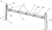
in the figure, a support base 1, a base 1.1, a right-angle trapezoidal plate 1.2, a guide rail groove 1.3, a guide rail 1.4, a stop block 1.41, a vertical plate 1.5, a reinforcing rib plate 1.6, a motor plate 1.7, a lifting platform 2, a bearing platform 2.1, a partition rod 2.11, an installation area 2.12, a motor port 2.13, a limit block 2.14, a reinforcing diagonal rib 2.15, a lifting bedplate 2.2, a guide rail sliding plate 2.21, a lead screw sliding plate 2.22, a double-row telescopic device 3, an installation base 3.1, a slide rail 3.2, a double-row telescopic arm 3.3, a telescopic motor 3.4, a lead screw 4, a servo motor 5, a guide rail sliding block 6, a lead screw installation base 7, a goods shelf 8.1, an installation base 9, a goods shelf 10, a communication module 10.1, a pulley assembly 11, a locking assembly 12, a locking device 13, an installation bottom plate 13.1, an installation bottom plate 13.2, a bolt 13.3, a connecting rod 13.4, a connecting rod 13.5, a gear installation support.
Detailed Description
The invention is described in further detail below with reference to the figures and specific embodiments for the understanding of those skilled in the art.
The horizontal storage and transfer system shown in fig. 1-14 comprises a shelf 8, wherein a support seat 1 is fixed on two sides of the shelf 8 through a mounting base 9 at the bottom; the supporting seat 1 comprises a base 1.1, right-angle trapezoidal plates 1.2 are symmetrically arranged on the base 1.1, guide rail grooves 1.3 are vertically arranged on the right-angle edges of the right-angle trapezoidal plates 1.2, the guide rail grooves 1.3 are higher than the right-angle trapezoidal plates 1.2, guide rails 1.4 are arranged in the guide rail grooves 1.3, and the top ends and the lower parts of the guide rails 1.4 are respectively provided with a stop block 1.41;
vertical plates 1.5 are arranged between the right-angle trapezoidal plates 1.2, a plurality of horizontal reinforcing rib plates 1.6 are arranged between the right-angle trapezoidal plates 1.2 and the vertical plates 1.5 at intervals from top to bottom, and a motor plate 1.7 is arranged between the top of each vertical plate 1.5 and the wall of each guide rail groove 1.3;
a lifting platform 2 which slides up and down is arranged between the supporting seats 1, a screw rod 4 is arranged on a vertical plate 1.5 at one end or two ends of the lifting platform 2, and the screw rod 4 penetrates through a motor plate 1.7 and a servo motor 5;
the lifting platform 2 comprises a bearing platform 2.1 which is horizontally arranged, the bearing platform 2.1 is provided with a plurality of partition rods 2.11, the bearing platform 2.1 is equally divided into a plurality of mounting areas 2.12 by the partition rods 2.11, and the centers of the mounting areas 2.12 are provided with motor ports 2.13; the two ends of the bearing platform 2.1 are symmetrically provided with the lifting bedplate 2.2, the lifting bedplate 2.2 slides back and forth on the supporting seat 1,
the lifting bedplate 2.2 comprises guide rail sliding plates 2.21 at two ends and a screw rod sliding plate 2.22 protruding in the middle, guide rail sliding blocks 6 sliding on the guide rails 1.4 are symmetrically arranged on the plate surface of the guide rail sliding plate 2.21 up and down, and a screw rod mounting seat 7 sliding in cooperation with a nut on the screw rod 4 is arranged on the plate surface of the screw rod sliding plate 2.22.
The edges at the two ends of the bearing platform 2.1 and the partition rod 2.11 are respectively provided with a limiting block 2.14, and reinforcing inclined ribs 2.15 are symmetrically arranged between the bearing platform 2.1 and the two guide rail sliding plates 2.21.
5 groups of double-row telescopic devices 3 are arranged on the bearing platform 2.1 at intervals; the double-row telescopic device 3 comprises mounting seats 3.1 arranged at two sides of a motor port 2.13, a slide rail 3.2 is arranged on the mounting seat 3.1, and double-row telescopic arms 3.3 are arranged on the upper surface of the slide rail 3.2; the side wall of the sliding rail 3.2 is fixed with a telescopic motor 3.4, and the telescopic motor 3.4 is embedded into the motor port 2.13.
The goods shelf 8 is divided into a plurality of layers of goods shelves 8.1 from top to bottom, a plurality of integral containers 10 are sequentially arranged in each layer of goods shelves 8.1 from one side to the other side, and a communication module 10.1 is arranged on the outer wall of one end of each container 10;
the middle of the bottom surface of each layer of the goods dividing rack 8.1 is provided with a locking component 12 along the width direction, and the locking components 12 comprise locking devices 13 which are symmetrically arranged at two sides of the goods dividing rack 8.1; the locking device 13 comprises a mounting base plate 13.1, a connecting plate 13.2 is arranged in the middle of the mounting base plate 13.1, the two ends of the mounting base plate 13.1 are respectively provided with a bolt 13.3, two side walls of the connecting plate 13.2 are respectively symmetrically provided with two connecting rods 13.4, and the two connecting rods 13.4 penetrate through a vertically arranged mounting support base 13.5 and are connected with the two sides of the bolt 13.3; a gear 13.6 is arranged on one side of the joint of the bolt 13.3 and the connecting rod 13.4, a rack bar 13.7 is arranged below the gear 13.6 in a matching way, and the rack bar 13.7 is connected with an electric cylinder 13.8 fixed on the mounting and supporting seat 13.5.
The transferring method based on the horizontal storage transferring system as shown in fig. 15 comprises the following steps:
1) the right double-row telescopic arm 3.3 is inserted into the bottom of the container 10 and is locked with the container 10 through the locking device 13, meanwhile, the left double-row telescopic arm 3.3 moves to the waist of the F container 10, the four stations are unlocked, the left double-row telescopic arm 3.3 pushes the whole row of containers 10 to the right, meanwhile, the right double-row telescopic arm 3.3 drags the A container 10 to move to the right, and when the communication module 10.1 detects that the B container 10 reaches the position of the original A container 10, the F, C, B container 10 at the moment is locked through the locking device 13;
2) the container 10 continuously moves to the right under the action of the double-row telescopic arms 3.3, and the lifting platform 2 drives the container 10 to lift to a target position right above the lifting platform 2 (namely, a position of a limit block) to wait for taking goods; after the goods are taken, the empty container 10 is ready to be returned to the warehouse;
3) the lifting platform 2 drives the empty container 10A to lift to a warehouse returning position (namely, a position right below the outlet of the container 10 at the warehouse outlet layer);
4) the returning of the A empty container 10 to the warehouse is similar to the discharging of the A empty container, the right double-row telescopic arm 3.3 drives the A empty container 10 to be tightly attached to the L container 10, meanwhile, the left double-row telescopic arm 3.3 is inserted into the bottom of the G container 10 and locked, then the four locking positions are unlocked, and the right double-row telescopic arm 3.3 drives the A empty container 10 to push the left container 10; meanwhile, the G container 10 is driven by the left double-row telescopic arm 3.3 to move leftwards, after the communication module 10.1 detects that the whole row of containers 10 moves one station, the containers 10 are locked at four locking positions, and the empty container 10A is returned to the warehouse;
5) g, the container 10 continuously moves to the left under the action of the left double-row telescopic arm 3.3 to a position right above the lifting platform 2 (namely the position of the limit block) to wait for lifting action;
6) the G container 10 is lifted to the upper layer (namely, a delivery layer) under the action of the lifting platform 2, then the left double-row telescopic arm 3.3 pushes the G container 10 to move right to be tightly attached to the F container 10, and the G container 10 is locked, so that the delivery and storage of the system are completed in one cycle; the container 10 at the delivery level B is ready for delivery and the flow of action is consistent with the delivery of container 10 at a.
Other parts not described in detail are prior art. Although the above embodiments have been described in detail, it is only a part of the embodiments of the present invention, rather than all embodiments, and other embodiments can be obtained without inventive step according to the present embodiments.
Claims (9)
1. A horizontal storage transfer system, it includes goods shelves (8), its characterized in that: a left supporting seat and a right supporting seat (1) are correspondingly arranged on two sides of the goods shelf (8); the goods shelf (8) is divided into a plurality of layers of goods shelves (8.1) from top to bottom, a plurality of integral containers (10) are sequentially arranged in each layer of goods shelves (8.1) from one side to the other side, pulley assemblies (11) are arranged in the middles of the inner walls of the two ends of each layer of goods shelves, the pulley assemblies (11) are also arranged on the bottom surface of each layer of goods shelves (8.1) from one end to the other end at intervals, the pulley assemblies (11) are all arranged along the width direction of the goods shelves (8.1), locking assemblies (12) are arranged in the middles of the bottom surfaces of each layer of goods shelves (8.1) along the width direction, and the locking assemblies (12) comprise locking devices (13) symmetrically arranged on the two sides of the goods shelves;
the lifting platform is characterized in that a lifting platform (2) which can slide up and down is arranged between the supporting seats (1), the lifting platform (2) is provided with a bearing platform (2.1) horizontally, lifting table plates (2.2) are symmetrically arranged at two ends of the bearing platform (2.1), the lifting table plates (2.2) slide back and forth on the supporting seats (1), and double-row telescopic devices (3) are arranged on the bearing platform (2.1) at intervals.
2. The horizontal storage transfer system of claim 1, wherein: the supporting seat (1) comprises a base (1.1), right-angle trapezoidal plates (1.2) are symmetrically arranged on the base (1.1), guide rail grooves (1.3) are vertically arranged on right-angle edges of the right-angle trapezoidal plates (1.2), the guide rail grooves (1.3) are higher than the right-angle trapezoidal plates (1.2), guide rails (1.4) are arranged in the guide rail grooves (1.3), vertical plates (1.5) are arranged between the right-angle trapezoidal plates (1.2), a plurality of horizontal reinforcing rib plates (1.6) are arranged between the right-angle trapezoidal plates (1.2) and the vertical plates (1.5) at intervals from top to bottom, and motor plates (1.7) are arranged between the tops of the vertical plates (1.5) and the groove walls of the guide rail grooves (1.3); and a screw rod (4) is arranged on the vertical plate (1.5) at one end or two ends of the lifting platform (2), and the screw rod (4) penetrates through the motor plate (1.7) and the servo motor (5).
3. The horizontal storage transfer system of claim 1 or 2, wherein: bearing platform (2.1) is provided with many subregion poles (2.11), subregion pole (2.11) are with bearing platform (2.1) etc. divide into a plurality of installing zones (2.12), motor mouth (2.13) have been seted up to installing zone (2.12) central authorities.
4. The horizontal storage transfer system of claim 3, wherein: the double-row telescopic device (3) comprises mounting seats (3.1) arranged on two sides of a motor port (2.13), a slide rail (3.2) is arranged on each mounting seat (3.1), and double-row telescopic arms (3.3) are arranged on the upper surfaces of the slide rails (3.2); the side wall of the sliding rail (3.2) is fixed with a telescopic motor (3.4), and the telescopic motor (3.4) is embedded into a motor port (2.13).
5. The horizontal storage transfer system of claim 3, wherein: the lifting bedplate (2.2) comprises guide rail sliding plates (2.21) at two ends and a lead screw sliding plate (2.22) protruding in the middle, guide rail sliding blocks (6) sliding on the guide rails (1.4) are symmetrically arranged on the plate surface of the guide rail sliding plate (2.21) up and down, and a lead screw mounting seat (7) sliding in a matched manner with a nut on the lead screw (4) is arranged on the plate surface of the lead screw sliding plate (2.22).
6. The horizontal storage transfer system of claim 2, wherein: the top end and the lower part of the guide rail (1.4) are respectively provided with a stop block (1.41).
7. The horizontal storage transfer system of claim 3, wherein: the bearing platform is characterized in that limiting blocks (2.14) are respectively arranged on the edges of the two ends of the bearing platform (2.1) and the partition rods (2.11), and reinforcing oblique ribs (2.15) are symmetrically arranged between the bearing platform (2.1) and the two guide rail sliding plates (2.21).
8. The horizontal storage transfer system of claim 1, wherein: the locking device (13) comprises an installation bottom plate (13.1), a connecting plate (13.2) is arranged in the middle of the installation bottom plate (13.1), lock tongues (13.3) are arranged at two ends of the installation bottom plate (13.1), two connecting rods (13.4) are symmetrically arranged on two side walls of the connecting plate (13.2), and the two connecting rods (13.4) penetrate through a vertically arranged installation supporting seat (13.5) and are connected with two sides of each lock tongue (13.3); spring bolt (13.3) and connecting rod (13.4) junction one side is provided with gear (13.6), gear (13.6) below cooperation is provided with rack bar (13.7), rack bar (13.7) are connected with electric jar (13.8) of fixing on erection bracing seat (13.5).
9. The horizontal storage transfer system of claim 1, wherein: the length of the pulley component (11) is the same as the width of the goods shelf (8), and the supporting seat (1) is fixed on two sides of the goods shelf (8) through a mounting base (9) at the bottom; the outer wall of one end of the container (10) is provided with a communication module (10.1).
Priority Applications (1)
| Application Number | Priority Date | Filing Date | Title |
|---|---|---|---|
| CN201920584436.8U CN210028811U (en) | 2019-04-24 | 2019-04-24 | Horizontal storage and transfer system |
Applications Claiming Priority (1)
| Application Number | Priority Date | Filing Date | Title |
|---|---|---|---|
| CN201920584436.8U CN210028811U (en) | 2019-04-24 | 2019-04-24 | Horizontal storage and transfer system |
Publications (1)
| Publication Number | Publication Date |
|---|---|
| CN210028811U true CN210028811U (en) | 2020-02-07 |
Family
ID=69361849
Family Applications (1)
| Application Number | Title | Priority Date | Filing Date |
|---|---|---|---|
| CN201920584436.8U Active CN210028811U (en) | 2019-04-24 | 2019-04-24 | Horizontal storage and transfer system |
Country Status (1)
| Country | Link |
|---|---|
| CN (1) | CN210028811U (en) |
Cited By (3)
| Publication number | Priority date | Publication date | Assignee | Title |
|---|---|---|---|---|
| CN112499073A (en) * | 2020-10-13 | 2021-03-16 | 海南科技职业大学 | Electronic tag goods shelf with distance adjustable function based on Internet of things |
| CN114751143A (en) * | 2022-04-21 | 2022-07-15 | 中国船舶重工集团公司第七一三研究所 | Modularization heavy load packing box handling device |
| CN114955339A (en) * | 2022-05-30 | 2022-08-30 | 浙江盛达铁塔有限公司 | Knapsack type stereoscopic warehouse |
-
2019
- 2019-04-24 CN CN201920584436.8U patent/CN210028811U/en active Active
Cited By (5)
| Publication number | Priority date | Publication date | Assignee | Title |
|---|---|---|---|---|
| CN112499073A (en) * | 2020-10-13 | 2021-03-16 | 海南科技职业大学 | Electronic tag goods shelf with distance adjustable function based on Internet of things |
| CN114751143A (en) * | 2022-04-21 | 2022-07-15 | 中国船舶重工集团公司第七一三研究所 | Modularization heavy load packing box handling device |
| CN114751143B (en) * | 2022-04-21 | 2024-05-28 | 中国船舶重工集团公司第七一三研究所 | Modularized heavy-load cargo box carrying device |
| CN114955339A (en) * | 2022-05-30 | 2022-08-30 | 浙江盛达铁塔有限公司 | Knapsack type stereoscopic warehouse |
| CN114955339B (en) * | 2022-05-30 | 2023-02-14 | 浙江盛达铁塔有限公司 | Knapsack type stereoscopic warehouse |
Similar Documents
| Publication | Publication Date | Title |
|---|---|---|
| CN112407718B (en) | Electronic container for storing electronic devices | |
| WO2021051806A1 (en) | Storage system | |
| JP2023519893A (en) | Autosave tower with multiple rows | |
| CN105438707A (en) | Method and device for automatically storing and taking goods in intensive storehouse | |
| CN108086755A (en) | Multilayer is without avoiding-type three-dimensional garage parking | |
| CN210762508U (en) | Warehouse logistics system | |
| WO2019238639A1 (en) | System for storing and transporting storage containers | |
| AU2015318768B2 (en) | Modular base for forming installations and method for storage by means of stacking and movement of cases | |
| CN110125891B (en) | Clamp switching and storage system | |
| KR101588567B1 (en) | Removable container type auto warehouse | |
| CN112897382A (en) | Intelligent warehousing equipment for logistics management | |
| EP3807175B1 (en) | System for storing and transporting storage containers | |
| KR102938431B1 (en) | Container storage and retrieval system | |
| CN110789893A (en) | Large-batch cargo storage and transportation equipment and transportation method | |
| CN212981731U (en) | Box multilayer pile up neatly device | |
| CN112849877A (en) | Automatic stereoscopic warehouse of circumference arrangement formula | |
| CN110304392B (en) | Combined automatic three-dimensional goods shelf | |
| CN112830141A (en) | Automatic stereoscopic warehouse | |
| EP3336025B1 (en) | A dynamic storage system | |
| CN215286568U (en) | Automatic stereoscopic warehouse for plates | |
| CN215400995U (en) | Automatic stereoscopic warehouse | |
| CN212374146U (en) | Movable automatic stereoscopic warehouse | |
| CN111942710B (en) | Transition equipment integrating temporary book storage and reversing transfer and control method thereof | |
| CN102561759B (en) | Three-dimensional garage for aeronautic dining trolleys | |
| CN120156803B (en) | Automatic stereoscopic warehouse based on logistics storage |
Legal Events
| Date | Code | Title | Description |
|---|---|---|---|
| GR01 | Patent grant | ||
| GR01 | Patent grant |