CN210077963U - prone face support - Google Patents
prone face support Download PDFInfo
- Publication number
- CN210077963U CN210077963U CN201821289285.5U CN201821289285U CN210077963U CN 210077963 U CN210077963 U CN 210077963U CN 201821289285 U CN201821289285 U CN 201821289285U CN 210077963 U CN210077963 U CN 210077963U
- Authority
- CN
- China
- Prior art keywords
- base
- prone face
- support
- prone
- face support
- Prior art date
- Legal status (The legal status is an assumption and is not a legal conclusion. Google has not performed a legal analysis and makes no representation as to the accuracy of the status listed.)
- Expired - Fee Related
Links
Images



Landscapes
- Accommodation For Nursing Or Treatment Tables (AREA)
Abstract
本实用新型公开了一种俯卧脸托。所述俯卧脸托包括底座(1)、卡槽底座块(3)、额头垫(5)、脸颊垫(6)和支撑杆(7);所述卡槽底座块(3)设置在所述底座(1)上且其上侧设置有多个凹型卡槽(4);所述支撑杆(7)的底部适于插入所述卡槽(4)内;所述额头垫(5)和所述脸颊垫(6)连接在所述支撑杆(7)的顶部处。本实用新型的俯卧脸托能够根据需要设置额头垫和脸颊垫的位置,从而可以保证俯卧脸托可以适应不同类型的脸型。本实用新型的俯卧脸托不仅可以让被护理人员体验舒适,还能达到结构简单、容易操作、辅助量低、省成本的效果。
The utility model discloses a prone face support. The prone face support comprises a base (1), a slotted base block (3), a forehead pad (5), a cheek pad (6) and a support rod (7); the slotted base block (3) is arranged on the A plurality of concave card slots (4) are arranged on and on the upper side of the base (1); the bottom of the support rod (7) is adapted to be inserted into the card slots (4); the forehead pad (5) and the The cheek pad (6) is connected at the top of the support rod (7). The prone face support of the utility model can set the positions of the forehead pad and the cheek pad according to the needs, thereby ensuring that the prone face support can be adapted to different types of faces. The prone face support of the utility model can not only make the nursing staff feel comfortable, but also achieve the effects of simple structure, easy operation, low auxiliary amount and cost saving.
Description
所属技术领域Technical field
本实用新型涉及医疗器械领域,尤其涉及一种俯卧脸托。The utility model relates to the field of medical equipment, in particular to a prone face support.
背景技术Background technique
目前,检测仪器越来越多,针对人体脸部的护理仪器也越来越多,传统的脸部护理没有脸托,或者说脸托仅仅是一个整块的棉垫,那么就会存在以下问题:At present, there are more and more testing instruments, and there are more and more nursing instruments for the human face. Traditional facial care has no face support, or the face support is just a whole piece of cotton pad, then there will be the following problems :
1)棉垫起的作用仅仅是在额头和脸颊部分凸起,以保护眼睛和鼻子,针对脸型差别较大的被护理人员,容易挤压到眼睛或者鼻子,甚至堵住口腔。1) The function of the cotton pad is to bulge on the forehead and cheeks to protect the eyes and nose. For the care recipients with different face shapes, it is easy to squeeze the eyes or nose, or even block the mouth.
2)当需要观察被护理人员脸部时,需要辅助人员将被护理人员脸部抬起,手持镜子,反射出被护理人员脸部,光线不足时,还需要另一辅助人员使用手电筒在旁边协助。从而造成人力物力的浪费,导致护理过程复杂和增加人力成本。2) When it is necessary to observe the face of the care recipient, an assistant is required to lift the face of the care recipient, hold a mirror, and reflect the face of the care recipient. When the light is insufficient, another assistant is required to use a flashlight to assist. . As a result, human and material resources are wasted, resulting in complicated nursing process and increased labor costs.
为此,针对现有的脸托,有必要提出一种让人舒适、简单且省成本的俯卧脸托。Therefore, for the existing face support, it is necessary to propose a comfortable, simple and cost-saving prone face support.
实用新型内容Utility model content
本实用新型的目的是提供一种让人舒适、简单且省成本的俯卧脸托。The purpose of the utility model is to provide a comfortable, simple and cost-saving prone face support.
本实用新型的一些实施例所要解决的技术问题是提供一种俯卧脸托,以根据患者的具体情况来调整脸托。The technical problem to be solved by some embodiments of the present invention is to provide a prone face support, so as to adjust the face support according to the specific conditions of the patient.
为此,本实用新型提供一种俯卧脸托,所述俯卧脸托包括底座、卡槽底座块、额头垫、脸颊垫和支撑杆;To this end, the utility model provides a prone face support, which comprises a base, a slotted base block, a forehead pad, a cheek pad and a support rod;
所述卡槽底座块设置在所述底座上,其上侧设置有至少一个凹型卡槽;The card slot base block is arranged on the base, and at least one concave card slot is arranged on its upper side;
所述支撑杆的底部适于插入所述卡槽内;The bottom of the support rod is suitable for being inserted into the card slot;
所述额头垫和所述脸颊垫连接在所述支撑杆的顶部处。The forehead pad and the cheek pad are attached at the top of the support rod.
优选地,所述卡槽底座块的数量为多个,且以可拆卸的方式设置在所述底座上,每个卡槽底座块上设置有至少一个凹型卡槽,所述底座的中部处设置有凹部,所述卡槽底座块设置在所述凹部内,所述底座的外周上表面设置有镜面。优选地,所述镜面由镀在底座整个上表面或上表面局部区域上的覆层形成。Preferably, the number of the card slot base blocks is multiple, and they are detachably arranged on the base, each card slot base block is provided with at least one concave card slot, and the middle of the base is provided with There is a concave part, the slot base block is arranged in the concave part, and the outer peripheral upper surface of the base is provided with a mirror surface. Preferably, the mirror surface is formed by a coating layer plated on the entire upper surface of the base or a partial area of the upper surface.
优选地,所述镜面包括多个子镜面,且至少部分子镜面以旋转可调的方式设置在所述底座的上部处。Preferably, the mirror surface includes a plurality of sub-mirror surfaces, and at least part of the sub-mirror surfaces are arranged at the upper portion of the base in a rotationally adjustable manner.
优选地,在所述底座的侧面和/或上表面处设置有LED光源,所述LED光源包括一个或更多个LED灯。Preferably, an LED light source is provided at the side and/or upper surface of the base, and the LED light source includes one or more LED lights.
优选地,所述支撑杆包括用于伸缩支撑杆的竖直伸缩关节,所述竖直伸缩关节用于伸长或者缩短支撑杆的高度。Preferably, the support rod includes a vertical telescopic joint for extending and retracting the support rod, and the vertical telescopic joint is used for extending or shortening the height of the support rod.
优选地,所述脸颊垫包括左脸颊垫和右脸颊垫,所述左脸颊垫、右脸颊垫和额头垫各自独立地以可拆卸的方式安装在相应支撑杆的顶部,且所述额头垫及所述左脸颊垫、右脸颊垫能够相对相应支撑杆水平转动。Preferably, the cheek pads include left cheek pads and right cheek pads, the left cheek pads, the right cheek pads and the forehead pads are each independently mounted on top of the corresponding support rods in a detachable manner, and the forehead pads and The left cheek pad and the right cheek pad can rotate horizontally relative to the corresponding support rod.
优选地,所述卡槽设置为开口尺寸小,内部尺寸大的卡扣凹槽。Preferably, the snap groove is configured as a snap groove with a small opening size and a large internal size.
优选地,所述底座在所述凹部的底部处设置有多个限位凹孔,在所述卡槽底座块的底部处设置有与所述限位凹孔相对应的限位凸起。Preferably, the base is provided with a plurality of limiting concave holes at the bottom of the recess, and a limiting protrusion corresponding to the limiting concave holes is provided at the bottom of the slot base block.
通过分设额头垫和脸颊垫,本实用新型的俯卧脸托具有舒适、简单且省成本的优点。进一步地,本实用新型一些实施例所解决的技术问题是提供一种俯卧脸托,以根据患者的具体情况来调整脸托。本实用新型一些实施例的俯卧脸托能够根据需要设置额头垫和脸颊垫的位置,从而可以保证俯卧脸托可以适应不同类型的脸型;此外,本实用新型一些实施例的俯卧脸托不仅可以让被护理人员体验舒适,还能达到结构简单、容易操作、辅助量低、省成本的效果。By separately arranging the forehead pad and the cheek pad, the prone face support of the present invention has the advantages of comfort, simplicity and cost saving. Further, the technical problem solved by some embodiments of the present invention is to provide a prone face support, so as to adjust the face support according to the specific conditions of the patient. The prone face support of some embodiments of the present invention can set the position of the forehead pad and the cheek pad as required, so as to ensure that the prone face support can be adapted to different types of faces; in addition, the prone face support of some embodiments of the present invention can not only make The nursing staff has a comfortable experience, and can also achieve the effects of simple structure, easy operation, low auxiliary amount and cost saving.
附图说明Description of drawings
下面结合附图和实施例对本实用新型进一步说明。The present utility model will be further described below in conjunction with the accompanying drawings and embodiments.
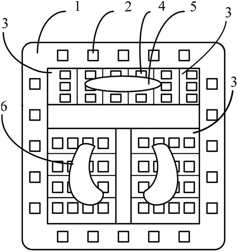
图1是本实用新型的一实施例的俯卧脸托的示意性俯视图。FIG. 1 is a schematic top view of a prone face support according to an embodiment of the present invention.
图2是图1所示俯卧脸托的示意性侧视图。FIG. 2 is a schematic side view of the prone face support shown in FIG. 1 .
图3是另一种俯卧脸托的示意性侧视图。Figure 3 is a schematic side view of another prone face support.
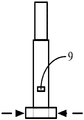
图4是支撑杆的示意性结构图。FIG. 4 is a schematic structural diagram of a support rod.
图5是本实用新型的另一实施例的俯卧脸托的示意性俯视图。5 is a schematic top view of a prone face support according to another embodiment of the present invention.
图6是图5所示俯卧脸托的示意性侧视图。FIG. 6 is a schematic side view of the prone face support shown in FIG. 5 .
图中,1--底座 2--LED灯 3--卡槽底座块 4--卡槽 5--额头垫 6--脸颊垫 7--支撑杆 8--竖直伸缩关节 9--支撑杆水平伸缩按钮 11—限位凹孔 31—限位凸起In the figure, 1--
具体实施方式Detailed ways
为了使实用新型的目的、技术方案及优点更加清楚明白,以下结合附图及实施例,对本实用新型进行进一步详细说明。应当理解,此处所描述的具体实施例仅仅用以解释本实用新型,并不用于限定本实用新型。In order to make the purpose, technical solutions and advantages of the utility model more clearly understood, the present utility model will be further described in detail below with reference to the accompanying drawings and embodiments. It should be understood that the specific embodiments described herein are only used to explain the present invention, and are not intended to limit the present invention.
如图1,展示的是俯卧脸托的示意性俯视图。该俯卧脸托包括底座1、LED 光源2、多个卡槽底座块3、卡槽4、额头垫5、脸颊垫6、支撑杆7。Figure 1 shows a schematic top view of the prone face support. The prone face support includes a
底座1采用正方形结构,并作为整个俯卧脸托的基础,底座1的上表层为镜子,所述的镜面由镀在底座整个上表面或上表面局部区域上的覆层形成。所述的镜面还可以包括多个子镜面,且至少部分子镜面以旋转可调的方式设置在所述底座的上部处。护理人通过调节子镜面的角度,可以更好地观察被护理人的脸部。The
底座1的中部处设置有凹部,所述卡槽底座块3设置在所述凹部内。换句话说,卡槽底座块3容置在所述凹部内。有利的是,所述底座1在所述凹部的底部处设置有多个限位凹孔11,在所述卡槽底座块3的底部处设置有与所述限位凹孔相对应的限位凸起31。限位凹孔11有利地采用圆形孔,以便于加工。The middle of the
可以理解的是,镜面设置在所述底座1的外周上表面处。也就是说,镜面是设置在凹部的径向外侧。It can be understood that the mirror surface is arranged on the upper surface of the outer circumference of the
在图示的实施例中,卡槽底座块3为矩形,其上设置有3个或4个卡槽4。需要指出的是,卡槽底座块3也能够采用正方形结构,且每个卡槽底座块3上仅仅设置一个卡槽4。或者,卡槽底座块3采用正方形结构,且每个卡槽底座块3上均匀设置4个卡槽4,也就是说,在每个角部处设置一个卡槽4。In the illustrated embodiment, the card
在底座的边缘处,也就是在底座的外周上表面处,也就是并未被卡槽底座块覆盖的区域边缘处,依次均匀地设置若干个LED灯,若干个LED灯组成一个 LED光源,LED光源与底座的镜子配合,可以保证给予脸托处充足的光源,以使护理人员能够清晰地看到被护理人员的脸部。可以理解的是,还可以仅仅在底座的侧面处设置LED灯,或者在底座上表面和侧面处都设置所述LED灯。LED灯的功率、数量和设置间距或设置位置,可以根据需要来调整。有利的是,LED灯设置为隐藏式的,也就是说LED灯不突出于底座的表面。At the edge of the base, that is, at the upper surface of the outer circumference of the base, that is, at the edge of the area not covered by the slot base block, several LED lights are evenly arranged in sequence, and several LED lights form an LED light source. The light source cooperates with the mirror on the base to ensure sufficient light source for the face support, so that the nursing staff can clearly see the face of the person being nursed. It can be understood that the LED lights can also be provided only on the side of the base, or the LED lights can be provided on both the upper surface and the side of the base. The power, quantity and setting spacing or setting position of LED lights can be adjusted as needed. Advantageously, the LED lights are provided hidden, that is to say the LED lights do not protrude from the surface of the base.
卡槽底座块设置在底座的中央位置,卡槽底座块表面均匀设置有尺寸相同的凹型卡槽,底座上的凹部可分为三个区域,分别是:额头区域、左脸颊区域、右脸颊区域。The card slot base block is set at the center of the base, and the surface of the card slot base block is evenly provided with concave card slots of the same size. The recess on the base can be divided into three areas: the forehead area, the left cheek area, and the right cheek area. .
其中,额头区域和脸颊区域之间设置一部分空白区域,该空白区域正好可对应人脸的眼睛部分,该空白区域的范围可选为2cm-3cn;左脸颊区域与右脸颊区域之间设置也设置一部分空白区域,该空白区域的范围可选1cm-2cm;设置空白区域的目的在于提高被护理人员的体验,也能使护理人员根据空白区域,调整额头垫和脸颊垫,使被护理人员的脸部位于脸托的中央位置。Among them, a part of the blank area is set between the forehead area and the cheek area, the blank area just corresponds to the eye part of the human face, and the range of the blank area can be selected as 2cm-3cn; the setting between the left cheek area and the right cheek area is also set A part of the blank area, the range of the blank area can be selected from 1cm-2cm; the purpose of setting the blank area is to improve the experience of the care recipient, and also enable the caregiver to adjust the forehead pad and cheek pad according to the blank area, so that the face of the care recipient can be adjusted. The part is located in the center of the face rest.
其中,卡槽为方形结构,卡槽均匀地分布在额头区域和脸颊区域处。Among them, the card slot is a square structure, and the card slot is evenly distributed at the forehead area and the cheek area.
如图2,展示的是俯卧脸托的侧视图,其中,卡槽内可以插入支撑杆,支撑杆的底部结构设置为可插入卡槽的方形结构;护理人员根据被护理人员的脸型大小和脸部结构特征,可以通过将支撑杆插入不同的卡槽内,使被护理人员的脸部达到最佳的位置。Figure 2 shows the side view of the prone face support, in which a support rod can be inserted into the card slot, and the bottom structure of the support rod is set to a square structure that can be inserted into the card slot; the nursing staff is based on the face size and face of the nursing staff. Due to the structural features, the face of the care recipient can reach the best position by inserting the support rod into different card slots.
其中,支撑杆分为上下两截,上截和下截通过竖直伸缩关节连接,护理人员可以调整竖直伸缩关节,调整被护理人员脸部上下位置,使被护理人员能够达到最舒适的状态。Among them, the support rod is divided into upper and lower sections. The upper section and the lower section are connected by a vertical telescopic joint. The nursing staff can adjust the vertical telescopic joint and adjust the upper and lower positions of the face of the nursing staff, so that the nursing staff can reach the most comfortable state. .
其中,支撑杆的顶部,设置有可拆卸安装的额头垫和脸颊垫,额头垫和脸颊垫为可活动结构,其能够相对支撑杆做水平转动,护理人员可通过转动额头垫和脸颊垫,使被护理人员的脸部达到最舒适的位置。Among them, the top of the support rod is provided with detachably installed forehead pads and cheek pads. The forehead pads and cheek pads are movable structures that can be rotated horizontally relative to the support rod. Nursing staff can rotate the forehead pad and cheek pad to make the The face of the person being cared for is in the most comfortable position.
如图3,展示的是支撑杆与卡槽的另一个插入方式,通过将支撑杆插入卡槽后,能够使支撑杆的底部卡住卡槽的内部,使支撑杆更加巩固。As shown in Figure 3, another insertion method of the support rod and the card slot is shown. After the support rod is inserted into the card slot, the bottom of the support rod can be stuck inside the card slot, so that the support rod is more solid.
图5与图6示出本实用新型的另一实施例的俯卧脸托。在图5、图6所示的俯卧脸托中,卡槽底座块3上设置有卡槽阵列。且卡槽底座块3的数量仅仅为三个。可以理解的是,还可以仅仅设置一个卡槽底座块,并在所述卡槽底座块上侧整个区域设置卡槽阵列。FIG. 5 and FIG. 6 show a prone face support according to another embodiment of the present invention. In the prone face support shown in FIG. 5 and FIG. 6 , a card groove array is provided on the card
此外,在图5与图6示出的俯卧脸托中,卡槽底座块3焊接、螺纹连接或以其它方式固定在底座1上。底座上并没有设置凹部来容置卡槽底座块3。In addition, in the prone face support shown in FIG. 5 and FIG. 6 , the
最后需要指出的是:以上实施例仅用以说明本实用新型的技术方案,而非对其限制。本领域的普通技术人员应当理解:可以对前述各实施例所记载的技术方案进行修改,或者对其中部分技术特征进行等同替换;这些修改或者替换,并不使相应技术方案的本质脱离本实用新型各实施例技术方案的精神和范围。Finally, it should be pointed out that the above embodiments are only used to illustrate the technical solutions of the present invention, but not to limit them. It should be understood by those of ordinary skill in the art that the technical solutions described in the foregoing embodiments may be modified, or some of the technical features thereof may be equivalently replaced; these modifications or replacements do not make the essence of the corresponding technical solutions depart from the present invention The spirit and scope of the technical solutions of the various embodiments.
Claims (9)
Priority Applications (1)
| Application Number | Priority Date | Filing Date | Title |
|---|---|---|---|
| CN201821289285.5U CN210077963U (en) | 2018-08-10 | 2018-08-10 | prone face support |
Applications Claiming Priority (1)
| Application Number | Priority Date | Filing Date | Title |
|---|---|---|---|
| CN201821289285.5U CN210077963U (en) | 2018-08-10 | 2018-08-10 | prone face support |
Publications (1)
| Publication Number | Publication Date |
|---|---|
| CN210077963U true CN210077963U (en) | 2020-02-18 |
Family
ID=69469417
Family Applications (1)
| Application Number | Title | Priority Date | Filing Date |
|---|---|---|---|
| CN201821289285.5U Expired - Fee Related CN210077963U (en) | 2018-08-10 | 2018-08-10 | prone face support |
Country Status (1)
| Country | Link |
|---|---|
| CN (1) | CN210077963U (en) |
Cited By (1)
| Publication number | Priority date | Publication date | Assignee | Title |
|---|---|---|---|---|
| CN113018045A (en) * | 2021-04-23 | 2021-06-25 | 四川大学华西医院 | Prone ventilation head supporting device |
-
2018
- 2018-08-10 CN CN201821289285.5U patent/CN210077963U/en not_active Expired - Fee Related
Cited By (1)
| Publication number | Priority date | Publication date | Assignee | Title |
|---|---|---|---|---|
| CN113018045A (en) * | 2021-04-23 | 2021-06-25 | 四川大学华西医院 | Prone ventilation head supporting device |
Similar Documents
| Publication | Publication Date | Title |
|---|---|---|
| CN217040616U (en) | Prone fixing frame for chest treatment | |
| CN206852453U (en) | The pillow of adjustable-angle | |
| CN211049973U (en) | Supporting frame for postoperative patient with eye fundus disease | |
| CN110236818A (en) | A kind of Secondary Control Stryker frame | |
| CN206508178U (en) | A kind of nursing in neurology frame with adjustment function | |
| CN204245782U (en) | Two butterfly neck-protecting pillow | |
| CN208064912U (en) | A kind of back-supported adjusting bed | |
| CN204698772U (en) | The postoperative support of retina shedding patient | |
| CN204654888U (en) | A kind of department of otorhinolaryngology multifunctional examining device | |
| CN218247715U (en) | airway opening device | |
| CN203468958U (en) | Head support capable of being adjusted at prone position | |
| CN207590758U (en) | An adjustment device for head fixation in thyroid surgery | |
| CN104799988B (en) | Diabetic foot care chair | |
| CN209575187U (en) | A kind of ophthalmology profession inspection chair | |
| CN208081428U (en) | A kind of liftable nursing holder | |
| CN211835123U (en) | Height-adjustable brain patient nursing pillow | |
| CN203802717U (en) | Prone position head rest | |
| KR101246439B1 (en) | Ear stand for eyeglass temples | |
| CN210750083U (en) | Head fixing device for ear-nose-throat department | |
| CN210748298U (en) | Can adjust beauty bed of gradient by a wide margin | |
| CN214803938U (en) | Neonate's head form adjusting device | |
| CN210932477U (en) | Neurosurgery nursing bracket | |
| CN220213254U (en) | Wheelchair with dining table | |
| CN205041044U (en) | Sitting posture correcting chair | |
| CN204106319U (en) | An ophthalmic surgery frame |
Legal Events
| Date | Code | Title | Description |
|---|---|---|---|
| GR01 | Patent grant | ||
| GR01 | Patent grant | ||
| CF01 | Termination of patent right due to non-payment of annual fee |
Granted publication date: 20200218 |
|
| CF01 | Termination of patent right due to non-payment of annual fee |