CN210120175U - Electric tool and main machine thereof - Google Patents
Electric tool and main machine thereof Download PDFInfo
- Publication number
- CN210120175U CN210120175U CN201921320391.XU CN201921320391U CN210120175U CN 210120175 U CN210120175 U CN 210120175U CN 201921320391 U CN201921320391 U CN 201921320391U CN 210120175 U CN210120175 U CN 210120175U
- Authority
- CN
- China
- Prior art keywords
- battery pack
- housing
- locking mechanism
- power tool
- casing
- Prior art date
- Legal status (The legal status is an assumption and is not a legal conclusion. Google has not performed a legal analysis and makes no representation as to the accuracy of the status listed.)
- Active
Links
Images


Classifications
-
- A—HUMAN NECESSITIES
- A01—AGRICULTURE; FORESTRY; ANIMAL HUSBANDRY; HUNTING; TRAPPING; FISHING
- A01G—HORTICULTURE; CULTIVATION OF VEGETABLES, FLOWERS, RICE, FRUIT, VINES, HOPS OR SEAWEED; FORESTRY; WATERING
- A01G3/00—Cutting implements specially adapted for horticultural purposes; Delimbing standing trees
- A01G3/04—Apparatus for trimming hedges, e.g. hedge shears
- A01G3/047—Apparatus for trimming hedges, e.g. hedge shears portable
- A01G3/053—Apparatus for trimming hedges, e.g. hedge shears portable motor-driven
-
- Y—GENERAL TAGGING OF NEW TECHNOLOGICAL DEVELOPMENTS; GENERAL TAGGING OF CROSS-SECTIONAL TECHNOLOGIES SPANNING OVER SEVERAL SECTIONS OF THE IPC; TECHNICAL SUBJECTS COVERED BY FORMER USPC CROSS-REFERENCE ART COLLECTIONS [XRACs] AND DIGESTS
- Y02—TECHNOLOGIES OR APPLICATIONS FOR MITIGATION OR ADAPTATION AGAINST CLIMATE CHANGE
- Y02E—REDUCTION OF GREENHOUSE GAS [GHG] EMISSIONS, RELATED TO ENERGY GENERATION, TRANSMISSION OR DISTRIBUTION
- Y02E60/00—Enabling technologies; Technologies with a potential or indirect contribution to GHG emissions mitigation
- Y02E60/10—Energy storage using batteries
Landscapes
- Life Sciences & Earth Sciences (AREA)
- Biodiversity & Conservation Biology (AREA)
- Ecology (AREA)
- Forests & Forestry (AREA)
- Environmental Sciences (AREA)
- Battery Mounting, Suspending (AREA)
Abstract
本实用新型公开了一种电动工具,包括:电机,驱动用于作业的工作组件;电池包,用于为电机供电;壳体,电池包可拆卸连接至壳体;锁定机构,用于连接壳体和电池包,锁定机构安装至壳体或者电池包;锁定机构具有锁定电池包与壳体使两者构成固定连接的锁定状态和释放电池包使其可相对于壳体沿第一直线方向滑动的解锁状态;弹出机构,与电池包配接且对电池包施加一个沿第一直线方向的驱动力;弹出机构包括:作用元件,与电池包配接;推力组件,连接壳体和作用元件。本实用新型能够提供一种电动工具及其主机,其电池包弹出结构更加简洁高效且安装更加方便。
The utility model discloses an electric tool, comprising: a motor, which drives a working component used for operation; a battery pack, which is used for supplying power to the motor; a casing, where the battery pack is detachably connected to the casing; a locking mechanism is used for connecting the casing body and battery pack, the locking mechanism is mounted to the casing or the battery pack; the locking mechanism has a locked state that locks the battery pack and the casing to form a fixed connection and releases the battery pack so that it can be relative to the casing in a first linear direction The sliding unlocked state; the ejection mechanism, which is matched with the battery pack and applies a driving force along the first linear direction to the battery pack; the ejection mechanism includes: an action element, which is matched with the battery pack; a thrust component, which is connected to the housing and the action element. The utility model can provide an electric tool and its main unit, the battery pack ejection structure is more concise and efficient, and the installation is more convenient.
Description
技术领域technical field
本实用新型涉及一种电动工具。The utility model relates to an electric tool.
背景技术Background technique
常用的电动工具包括用来供电的电池包,电池包一般安装在电动工具的壳体上。随身电池包容量以及重量的增大,电池包的拆卸以及安装结构需要随着优化。目前市面存在具有电池包弹出结构的电动工具,用于更加方便地拆卸电池包。但是大多数电池包弹出结构具有可靠性低,传动效率低以及电池包安装不稳等缺陷。Commonly used power tools include a battery pack for power supply, and the battery pack is generally installed on the housing of the power tool. As the capacity and weight of the portable battery pack increase, the disassembly and installation structure of the battery pack needs to be optimized accordingly. At present, there are electric tools with a battery pack ejection structure on the market, which are used to disassemble the battery pack more conveniently. However, most battery pack ejection structures have defects such as low reliability, low transmission efficiency, and unstable battery pack installation.
例如,图1所示的公告号为CN102729224A 的专利揭示了辅助电池包弹出结构,其中,弹出电池包的驱动力作用方向与电池包第一直线方向不在同一直线上,而是采用了异形杠杆进行传动实现电池包弹出,由于杠杆力臂的存在导致弹出结构与锁定电池包的锁定机构存在高度差,这使得电池包容易发生侧倾,安装不稳,同时该弹出结构设计较为复杂,杠杆结构设计不合理时电池包弹出效率低。又如,图2所示的公告号为CN100540190C 的专利揭示了一种用于电池组的弹射机构,其中,弹出结构与锁定电池包的锁定机构基本位于同一平面上,但是弹簧直接连接至壳体内表面且直接作用于电池包,这导致弹簧和电池包的安装不便,弹簧作用至电池包的推力不均等问题。For example, the patent with the publication number CN102729224A shown in FIG. 1 discloses an auxiliary battery pack ejection structure, wherein the action direction of the driving force for ejecting the battery pack is not on the same straight line as the first linear direction of the battery pack, but a special-shaped lever is used. The battery pack is ejected by transmission. Due to the existence of the lever arm, there is a height difference between the ejection structure and the locking mechanism for locking the battery pack, which makes the battery pack prone to roll and unstable installation. When the design is unreasonable, the ejection efficiency of the battery pack is low. For another example, the patent with the publication number CN100540190C shown in FIG. 2 discloses an ejection mechanism for a battery pack, wherein the ejection structure and the locking mechanism for locking the battery pack are basically located on the same plane, but the spring is directly connected to the casing The surface directly acts on the battery pack, which leads to inconvenience in the installation of the spring and the battery pack, and the problem of uneven thrust applied by the spring to the battery pack.
实用新型内容Utility model content
为解决现有技术的不足,本实用新型的目的在于提供一种电动工具及其主机,其电池包弹出结构更加简洁高效且安装更加方便。In order to solve the deficiencies of the prior art, the purpose of the present invention is to provide an electric tool and its main unit, whose battery pack ejection structure is more concise and efficient, and the installation is more convenient.
为了实现上述目标,本实用新型采用如下的技术方案:In order to achieve the above-mentioned goals, the utility model adopts the following technical scheme:
一种电动工具,包括:电机,驱动用于作业的工作组件;电池包,用于为电机供电;壳体,电池包可拆卸连接至壳体;锁定机构,用于连接壳体和电池包,锁定机构安装至壳体或者电池包;锁定机构具有锁定电池包与壳体使两者构成固定连接的锁定状态和释放电池包使其可相对于壳体沿第一直线方向滑动的解锁状态;弹出机构,与电池包配接且对电池包施加一个沿第一直线方向的驱动力;弹出机构包括:作用元件,与电池包配接;推力组件,连接壳体和作用元件;当锁定机构处于解锁状态时,推力组件对作用元件施加沿第一直线方向的推力使得作用元件相对于壳体沿第一直线方向移动。A power tool, comprising: a motor for driving a working component for operation; a battery pack for supplying power to the motor; a housing, the battery pack being detachably connected to the housing; a locking mechanism for connecting the housing and the battery pack, The locking mechanism is mounted to the casing or the battery pack; the locking mechanism has a locked state in which the battery pack and the casing are locked to form a fixed connection and an unlocked state in which the battery pack is released so that it can slide relative to the casing in a first linear direction; The ejection mechanism is matched with the battery pack and applies a driving force along the first linear direction to the battery pack; the ejection mechanism includes: an action element, mated with the battery pack; a thrust assembly, connected to the housing and the action element; when the locking mechanism When in the unlocked state, the thrust assembly exerts a thrust along the first linear direction on the acting element, so that the acting element moves relative to the housing along the first linear direction.
进一步地,壳体连接或形成有用于安装电池包的电池包座,电池包座上设置有两组以上弹出机构。Further, the casing is connected to or formed with a battery pack seat for installing the battery pack, and more than two sets of ejection mechanisms are provided on the battery pack seat.
进一步地,两组弹出机构在垂直于第一直线的方向对称设置。Further, the two groups of ejection mechanisms are symmetrically arranged in a direction perpendicular to the first straight line.
进一步地,电池包包括与作用元件配接的配接部;作用元件至少部分外露于壳体;作用元件与电池包构成面接触。Further, the battery pack includes a fitting portion that is matched with the action element; the action element is at least partially exposed to the casing; the action element is in surface contact with the battery pack.
进一步地,至少部分作用元件设置于壳体内部,电池包包括向外凸出的凸出部,壳体开设有允许凸出部通过的孔。Further, at least part of the acting element is disposed inside the casing, the battery pack includes a protruding portion protruding outward, and the casing is provided with a hole allowing the protruding portion to pass through.
进一步地,电池包座形成有用于安装电池包的安装面,安装面基本平行于第一直线,锁定机构安装至安装面;弹出机构安装至基本与安装面垂直的侧端面;锁定机构与弹出机构基本位于同一平面内。Further, the battery pack seat is formed with a mounting surface for mounting the battery pack, the mounting surface is substantially parallel to the first straight line, the locking mechanism is mounted to the mounting surface; the ejection mechanism is mounted to the side end surface substantially perpendicular to the mounting surface; The institutions are basically located in the same plane.
进一步地,锁定机构包括限位部,电池包包括与限位部配合的接收部;电池包座形成有用于安装电池包的安装面,安装面基本平行于第一直线,限位部安装至安装面,作用元件安装至基本与安装面垂直的侧端面;限位部与作用元件基本位于同一平面内。Further, the locking mechanism includes a limiting portion, and the battery pack includes a receiving portion that cooperates with the limiting portion; the battery pack seat is formed with a mounting surface for installing the battery pack, the mounting surface is substantially parallel to the first straight line, and the limiting portion is mounted to On the mounting surface, the acting element is mounted on the side end surface substantially perpendicular to the mounting surface; the limiting part and the acting element are basically located in the same plane.
进一步地,弹出机构还包括用于安装推力组件的底座;底座安装至壳体内部或者与壳体一体成型;底座和作用元件上均设置有用于安装推力组件的安装部。Further, the ejection mechanism further includes a base for installing the thrust assembly; the base is installed inside the casing or integrally formed with the casing; both the base and the acting element are provided with a mounting portion for installing the thrust assembly.
进一步地,推力组件能够沿第一直线方向发生弹性形变;安装部为固定连接或者一体成型于底座或者作用元件的棱柱,推力组件套装至安装部。Further, the thrust assembly can be elastically deformed along the first linear direction; the mounting portion is a prism that is fixedly connected or integrally formed on the base or the acting element, and the thrust assembly is sleeved on the mounting portion.
进一步地,弹出机构还包括在垂直于第一直线的方向对推力组件进行限位的阻挡部,阻挡部连接或一体成型于底座或者壳体。Further, the ejecting mechanism further includes a blocking portion for limiting the thrust assembly in a direction perpendicular to the first straight line, and the blocking portion is connected to or integrally formed with the base or the housing.
进一步地,作用元件的外轮廓呈长方体形,作用元件的表面与安装面基本贴合。Further, the outer contour of the acting element is in the shape of a rectangular parallelepiped, and the surface of the acting element is substantially fitted with the mounting surface.
一种电动工具的主机,主机用于安装电池包,主机包括:电机,由电池包供电;壳体,电池包可拆卸连接至壳体;锁定机构,用于连接壳体和电池包,锁定机构安装至壳体或者电池包;锁定机构具有锁定电池包与壳体使两者构成固定连接的锁定状态和释放电池包使其可相对于壳体沿第一直线方向滑动的解锁状态;弹出机构,与电池包配接且对电池包施加一个沿第一直线方向的驱动力;弹出机构包括:作用元件,与电池包配接;推力组件,连接壳体和作用元件,推力组件可对作用元件产生沿第一直线方向的推力,作用元件与推力组件沿第一直线方向构成联动。A main unit of an electric tool, the main unit is used to install a battery pack, and the main unit includes: a motor, which is powered by the battery pack; a casing, the battery pack is detachably connected to the casing; a locking mechanism, used for connecting the casing and the battery pack, the locking mechanism Installed to the casing or the battery pack; the locking mechanism has a locked state that locks the battery pack and the casing to form a fixed connection and an unlocked state that releases the battery pack so that it can slide relative to the casing along the first linear direction; the ejection mechanism , mating with the battery pack and applying a driving force along the first linear direction to the battery pack; the ejection mechanism includes: an action element, which is mated with the battery pack; a thrust assembly, which connects the housing and the action element, and the thrust assembly can act on the The element generates a thrust along the first linear direction, and the acting element and the thrust component form a linkage along the first linear direction.
本实用新型的有益之处在于:本实用新型的电动工及其主机具通过对电动工具的电池包弹出结构进行优化,从而使得该弹出结构更加简洁高效且安装更加方便。The advantages of the utility model are that the electric power tool and its main tool of the utility model optimize the ejection structure of the battery pack of the electric tool, so that the ejection structure is more concise and efficient, and the installation is more convenient.
附图说明Description of drawings
图1是一现有技术的结构示意图;Fig. 1 is the structural representation of a prior art;
图2是另一现有技术的结构剖视图;Fig. 2 is a structural cross-sectional view of another prior art;
图3是本实用新型的第一实施例的电动工具的示意图;Fig. 3 is the schematic diagram of the electric tool of the first embodiment of the present invention;
图4是图3中的电动工具的部分结构的立体图;4 is a perspective view of a partial structure of the power tool in FIG. 3;
图5是图3中的电动工具的电池包的立体图;FIG. 5 is a perspective view of the battery pack of the power tool in FIG. 3;
图6是图5中的电池包的另一个角度的立体图;FIG. 6 is a perspective view of the battery pack of FIG. 5 from another angle;
图7是图3中的电动工具的部分结构的立体图;7 is a perspective view of a partial structure of the power tool in FIG. 3;
图8是图3中的电动工具的用来适配电池包的结构的示意图,包括弹出机构与锁定机构;8 is a schematic diagram of the structure of the power tool in FIG. 3 for adapting to the battery pack, including an ejection mechanism and a locking mechanism;
图9是本实用新型的第一实施例的电动工具的电池包安装至壳体时的示意图;FIG. 9 is a schematic diagram of the battery pack of the power tool according to the first embodiment of the present invention when it is installed on the housing;
图10是图8中的一组弹出机构的平面图;Figure 10 is a plan view of a set of ejection mechanisms in Figure 8;
图11是图10中的弹出机构的爆炸图;Figure 11 is an exploded view of the ejection mechanism in Figure 10;
图12是图3中的电动工具的部分结构的剖视图,包括弹出机构;Figure 12 is a cross-sectional view of a portion of the structure of the power tool in Figure 3, including an ejection mechanism;
图13是图3中的电动工具的部分结构的平面示意图;13 is a schematic plan view of a partial structure of the power tool in FIG. 3;
图14是图3中的电动工具的部分结构的俯视图;Figure 14 is a top view of the partial structure of the power tool in Figure 3;
图15是图3中的电动工具的电机、风扇以及传动装置的平面图;Figure 15 is a plan view of the motor, fan and transmission of the power tool in Figure 3;
图16是图15中的电动工具的电机以及传动装置的部分结构的剖视图;Fig. 16 is a sectional view of a part of the structure of the motor and the transmission device of the power tool in Fig. 15;
图17是本实用新型的第二实施例的电动工具的主机的示意图。17 is a schematic diagram of the main body of the power tool according to the second embodiment of the present invention.
具体实施方式Detailed ways
图1所示为本实用新型的第一实施例的电动工具100。本实用新型的电动工具100具体以修枝机为例,当然,电动工具100也可以是链锯、吹风机、打草机、螺丝批、砂光机等其他手持式电动工具,也可以是手推式割草机、手推式扫雪机等其他手推式电动工具,也可以是骑乘式割草机、扫雪机、洒水机等骑乘式电动工具,总之,只要是本实用新型所限定的技术方案所能适用的电动工具均属于本实用新型的保护范围。FIG. 1 shows a
如图3至图6所示,电动工具100包括工作组件11、主机12、电池包13。主机12包括电机121,电池包13为电机121供电以使电机121能够驱动工作组件11运动以实现电动工具100的功能,本实施中工作组件11为用于切割植被的刀片组件,具体为修枝剪;主机12还包括壳体122,壳体122围绕形成有容纳电机121的容纳空间,电池包13与壳体122构成可拆卸连接。As shown in FIGS. 3 to 6 , the
电动工具100还包括锁定机构14和弹出机构15。锁定机构14用于连接壳体122和电池包13,在电池包13安装至壳体122后将电池包13锁定至壳体122,锁定机构14安装至壳体122或者电池包13,本实施例中锁定机构14安装至壳体122;锁定机构14具有锁定电池包13与壳体122使两者不发生相对运动的锁定状态和电池包13可相对于壳体122滑动的解锁状态。当电池包13安装至壳体122时弹出机构15与电池包13配接,弹出机构15对电池包13施加一个沿第一直线101方向的驱动力,在该驱动力的作用下,锁定机构14处于解锁状态时弹出机构15使电池包13相对于壳体122弹出。具体的,在锁定机构14处于解锁状态时弹出机构15能够在无外力作用下能够使电池包13相对于壳体122沿弹出,第一直线101方向如图4中箭头所示。需要说明的是,电池包13相对于壳体122沿弹出指的是电池包13和电机13断开电联接,电池包13不一定完全与壳体122脱离。The
壳体122连接或形成有用于安装电池包13的电池包座131;本实施例中电池包座131由壳体122自身形成,也即是说与壳体122一体成型。电池包座131与电池包13构成可拆卸的滑动连接;具体地,电池包座131上设置有供电电池包13滑动的滑轨,电池包13上设置有与滑轨配合的滑槽;作为一种可选择的实施方式,电池包座131上设置供电池包13滑动的滑槽,电池包13上设置有与滑槽配合的滑轨。The
电池包座131上设置有两组以上弹出机构15;本实施例中,电池包座131上沿垂直于第一直线101方向的方向对称设置有两组弹出机构15,使得电池包13受到均衡作用的驱动力。本实施例中,电池包座131上沿垂直于电池包13第一直线101方向的方向对称设置有两组弹出机构15,如此位置设计能够使得电池包13的安装更加稳固,不会产生宽度方向的偏斜。更具体地,两组弹出机构15分别设置于电池包座131长度方向的一端、电池包座131宽度方向的边缘。这样的位置设计能够充分利用电池包13安装至电池包座131时电池包13与弹出机构15的互相作用,也即是使得弹出机构15对电池包13中心的力矩更大,使得电池包13在弹出结构的作用下安装更加稳定。当然,可以理解的,弹出机构15也可以设置于电池包座131的其他位置,在此不作限制。Two or more sets of
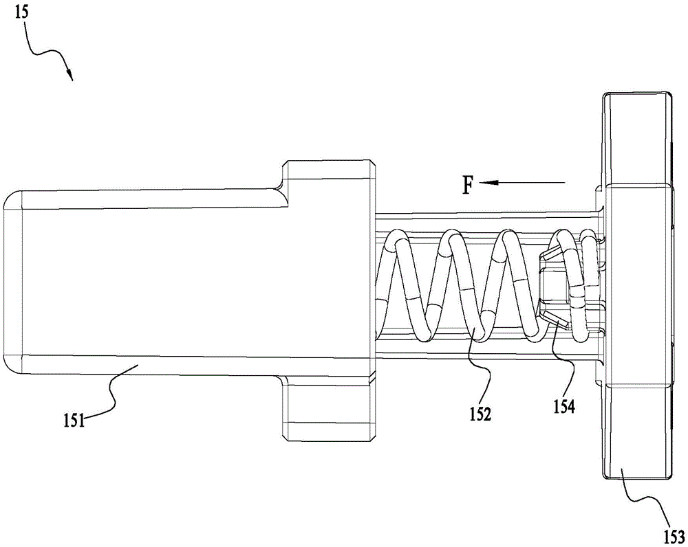
如图4至图8所示,弹出机构15包括作用元件151和第二推力组件152。作用元件151安装至壳体122,与电池包13配接;电池包13包括与作用元件151配接的配接部132。第二推力组件152连接壳体122与作用元件151,第二推力组件152优选弹性件且可沿电池包13第一直线101方向缩短或伸长;作用元件151在第二推力组件152或者外力作用下可相对于壳体122沿第一直线101方向移动,具体地,作用元件151在第二推力组件152沿第一直线101方向的推力作用下能够相对于壳体122沿第一直线101方向移动。当锁定机构14处于锁定状态时,电池包13在锁定机构14的作用下被固定至壳体122,此时第二推力组件152处于压缩状态,作用元件151对电池包13施加有一个沿第一直线101方向的推力;当锁定机构14处于解锁状态时,锁定机构14不再对电池包13施加使其固定至壳体122的作用力,此时在第二推力组件152的推力作用下电池包13相对于电池包座131弹出,第二推力组件152对作用元件151施加沿第一直线方向101的推力使得作用元件151相对于壳体122沿第一直线方向101移动。As shown in FIGS. 4 to 8 , the
作用元件151至少部分外露于壳体122,配接部132为电池包13向内凹陷的凹陷部,该凹陷部与与外露于壳体122的作用元件151相配接从而实现作用元件151对电池包13的弹出作用。作为一种可选的实施方式,至少部分作用元件151设置于壳体122内部,电池包13包括向外凸出的凸出部,壳体122开设有允许凸出部通过的孔;当电池包13安装至壳体122时,凸出部伸入壳体122内部与作用元件151配接。The
作用元件151与电池包13作用而非第二推力组件152直接作用于电池包使得第二推力组件152对电池包13施加的推力更加均匀,使得电池包13的安装和弹出都更加稳定,进一步的,作用元件151与配接部132为面接触。具体地,作用元件151的外轮廓呈长方体形,更具体地,作用元件151为一侧面镂空的长方体,配接部132包括一内凹的端面,作用元件151的另一侧面抵触至电池包13的端面从而使得电池包13受力弹出。The
第二推力组件152推力作用的方向与电池包13第一直线方向101一致,这使得第二推力组件152驱动电池包13弹出的传动过程更加简捷高效。电池包座131还包括多个电连接至电机121的极片,电池包13包括多个与极片构成电连接的连接端子。The direction in which the thrust of the
如图7至图9所示,由于电池包13安装至电池包座131时实际上受到锁定机构14与弹出机构15两者的作用力,当锁定机构14与弹出机构15不在同一平面上,也即是存在一定的高度差时,电池包13容易发生侧倾,导致安装不稳。因此,本实用新型中,锁定机构14与弹出机构15基本设置于同一平面上,具体实现结构如下:电池包座131形成有用于安装电池包13的安装面131a,安装面131a基本平行于第一直线101,锁定机构14安装至安装面131a,弹出机构15安装至与安装面131a垂直的侧端面且靠近安装面131a。As shown in FIGS. 7 to 9 , since the
具体地,在本实施例中,锁定机构14包括限位部141,电池包13包括与限位部141配合的接收部133;电池包座131形成有用于安装电池包13的安装面131a,安装面131a基本平行于第一直线101,限位部141安装至安装面131a,作用元件151安装至与安装面131a垂直的侧端面且靠近安装面131a;限位部141与作用元件151基本位于同一平面内,作用元件151的表面与安装面131a基本贴合。可以理解的,由于与电池包13实际发生配接的是锁定机构14的限位部141和弹出机构15的作用元件151,因此,若限位部141与作用元件151基本位于同一平面内,电池包13也基本不会发生侧倾。作为一种可选择的实施方式,电池包13上设置有限位部141,锁定机构14包括与限位部141配合的接收部133。更具体地,限位部141为卡扣,接收部133为与卡扣配合的卡槽。当然,限位部141和接收部133的结构还可以是其他结构,例如磁性相反的两个磁铁,在此不作限制。Specifically, in this embodiment, the locking mechanism 14 includes a limiting
锁定机构14还包括供用户操作以锁定或解锁电池包13的操作部142,操作部142与限位部141构成连接或者一体成型。本实施例中,限位部141和操作部142一体成型且两者之间安装有一转轴143,使得操作部142和限位部141能够绕该转轴143转动。锁定机构14还包括第一推力组件144,第一推力组件144安装至限位部141或者操作部142,使得在无外力作用时将限位部141保持在能够锁定电池包13的锁定位置。第一推力组件144优选能够发生弹性形变的弹性组件和包括磁铁和磁性组件,本实施例中第一推力组件144优选弹簧。The locking mechanism 14 further includes an operating
如图10至12所示,弹出机构15还包括用于安装第二推力组件152的底座153,底座153与壳体122构成可拆卸连接;底座153安装至壳体122内部;底座153和作用元件151上均设置有用于安装第二推力组件152的安装部154,具体地,底座153的底面153a在第二推力组件152的作用下抵触至壳体122内表面,安装部154设置于作用元件151的内端面以及底座153的外表面。弹出机构15的安装顺序为:将弹出机构15组装好以后再将其作为一个整体安装至壳体122,具体地,将第二推力组件152的一端安装至作用元件151的安装部154,再将底座153安装至第二推力组件152的另一端,然后将弹出机构15的作用元件151从壳体122后端通过壳体122上开设的孔穿过壳体122并抵触至壳体122,接着对底座153施加一个压力压缩第二推力组件152同时将底座153推入壳体122。作为一种可选择的实施方式,底座153与壳体122一体成型,安装部154设置于作用元件151的内端面以及壳体122的外表面,弹出机构15的安装顺序为:将将第二推力组件152的一端安装至壳体122的安装部154,再将作用元件151安装至第二推力组件152的另一端。As shown in FIGS. 10 to 12 , the
优选的,安装部154引导第二推力组件152发生弹性形变的方向,安装部154为固定连接或者一体成型于底座153和作用元件151的棱柱,棱柱的延伸方向平行于第一直线101。第二推力组件152具体为弹簧,第二推力组件152套装至安装部154表面。第二推力组件152优选能够发生弹性形变的弹性组件和包括磁铁和磁性组件,本实施例中第二推力组件152优选弹簧。Preferably, the mounting
弹出机构15还包括在垂直于第一直线方向101对第二推力组件152进行限位的阻挡部155,阻挡部155连接或一体成型于底座153或者壳体122。具体地,阻挡部155包括沿第二推力组件152的长度方向延伸的一个阻挡面155a,阻挡第二推力组件152发生偏移或者歪斜;另外,阻挡部155上连接有垂直于阻挡面155a的加强筋156,加强筋156也垂直于底座153。在垂直于第一直线方向101相对设置的两组弹出机构15的底座153互相接触或者抵触,用于进一步地对弹出机构15在垂直于第一直线方向101的方向进行限位,避免其安装不稳。The
如图13至图16所示,电动工具100(如图3所示)还包括传动传动装置123,传动装置123设置于电机121和工作组件11之间实现电机121和工作组件11之间的动力传递。电机121包括转子轴121a、转子套筒121b以及定子铁芯121c,其中,转子轴121a绕第一轴线101a转动;转子套筒121b与转子轴121a连接;定子铁芯121c设置于转子套筒121b内。优选的,电机121为外转子电机121,转子轴121a设置于转子套筒121b内部。传动装置123包括减速组件和箱体123a,减速组件接收电机121输出的动力;箱体123a容纳减速组件;其中,箱体123a设置于壳体122内;转子轴121a伸入至箱体123a内;转子套筒121b在一个垂直于第一轴线101a的平面内的正投影位于箱体123a在该平面内的正投影内。或者说,电机121在垂直于第一轴线101a的平面内的正投影位于箱体123a在该平面内的正投影内。也即是说,本发明的中的电机121相比传动装置123在垂直于第一轴线101a方向上具有更小的尺寸,从而使得电动工具100的体积更小,重量更轻。作为一种可选择的实施方式,转子轴121a可以不伸入箱体123a内,减速组件包括伸入箱体123a外的与转子轴121a构成连接的连接轴,转子轴121a的轴线与连接轴的轴线重合或者平行。As shown in FIG. 13 to FIG. 16 , the power tool 100 (as shown in FIG. 3 ) further includes a
电机121沿平行于第一轴线101a方向,电机121设置于电池包13和工作组件11的上方,这使得用户在纵向切割时,整机的重量分布较为均匀,以防止电动工具100发生大幅度的歪斜。电动工具100包括供用户握持的主把手124a和副把手124b,主把手124a和副把手124b安装至壳体122或者由壳体122围绕形成,主把手124a沿前后方向延伸,副把手124b至少部分沿垂直于前后和上下方向的左右方向延伸。沿前后方向,主把手124a相对于副把手124b更加靠近电池包13,副把手124b相对于主把手124a更加靠近工作组件11。沿前后方向,电机121和电池包13设置于副把手124b的一侧,工作组件11设置于副把手124b的另一侧,这使得用户在握持电动工具100时沿前后方向重量分布更加均匀。具体的,沿前后方向,电机121设置于电池包13和副把手124b之间,电机121设置于主把手124a和副把手124b之间。The
如图4和图14所示,本发明中,壳体122具有一个中分面A,壳体122关于中分面A沿左右方向基本对称,也即是说,壳体122由左壳体122a和右壳体122b两部分安装而成。电机121基本关于中分面A对称;事实上,整个电动工具100基本关于中分面A对称,这使得电动工具100(如图3所示)的重心分布更加合理,更加符合人机工程学的设计要求。As shown in FIG. 4 and FIG. 14 , in the present invention, the
如图15和图16所示,转子套筒121b的直径D与定子铁芯121c的叠长L的比值大于等于1.5且小于等于3;进一步地,转子套筒121b的直径D与定子铁芯121c的叠长L的比值大于等于1.7小于等于2.5;优选的,转子套筒121b的直径D与定子铁芯121c的叠长L的比值约为2.3或者1.75,转子套筒121b的直径D小于等于35毫米,定子铁芯121c的叠长L优选15毫米或者20毫米。As shown in FIGS. 15 and 16 , the ratio of the diameter D of the rotor sleeve 121b to the stack length L of the
箱体123a包括围绕部123b和顶盖123c,围绕部123b用于围绕至少部分减速组件;顶盖123c连接至围绕部123b的上侧;顶盖123c支撑电机121。具体地,围绕部123b形成有沿第一轴线101a周向密封的容纳空间,至少部分减速组件设置于该容纳空间内部。顶盖123c从第一轴线101a方向上方覆盖围绕部123b形成的容纳空间。The
减速组件的传动方式优选行星齿轮传动或者直齿轮传动,本实施例中,采用两级行星齿轮传动系统,减速组件具体包括太阳轮123d、内齿圈123e和行星轮123f;太阳轮123d与电机轴连接,本实施例中,太阳轮123d与转子轴121a连接。内齿圈123e围绕太阳轮123d;行星轮123f分别于内齿圈123e和太阳轮123d啮合。其中,转子套筒121b的直径D与内齿圈123e的外直径D1的差值大于等于0且小于等于6毫米,进一步地,转子套筒121b的直径D与内齿圈123e的外直径D1的差值大于等于1且小于等于4毫米,本实施例中,转子套筒121b的直径D与内齿圈123e的外直径D1的差值约为2毫米,需要说明的是,两级行星齿轮传动系统的内齿圈123e的外直径基本相等。减速组件包括用于输出动力的输出轴123g;转子轴121a的转速与输出轴123g的转速的比值为减速组件的减速比R;转子套筒121b的直径D与减速比R的比值大于等于2.3毫米且小于等于3毫米,进一步地,转子套筒121b的直径D与减速比R的比值大于等于2.5毫米且小于等于2.8毫米。优选的,两级行星齿轮传动系统包括高速级传动和低速级传动,两级行星齿轮传动系统的总传动比R约为12.053,高速级传动比约为3.375,低速级传动比约为3.571。作为另一种可选的实施方式,两级行星齿轮传动系统的总传动比R约为13.3,其中,高速级传动比约为3.714,低速级传动比约为3.571。The transmission mode of the deceleration assembly is preferably planetary gear transmission or spur gear transmission. In this embodiment, a two-stage planetary gear transmission system is adopted. The deceleration assembly specifically includes a
电机121的重量大于等于100 g且小于等于155 g,进一步地,电机121的重量大于等于120 g且小于等于150 g。电机121的最大输出功率P与转子套筒121b的直径D的比值大于等于10瓦每毫米且小于等于13瓦每毫米。本发明中,电机121转子套筒121b直径较小且电机121的最大输出功率足够大,使得电动工具100在满足工作性能要求时具有较小的体积和较轻的重量。The weight of the
电动工具还包括风扇124,风扇124安装至转子轴121a;本实施例中,风扇124安装至电机121的一端,且基本覆盖住电机121的端面,从而使得电机121得到充分的散热。风扇124的直径大于等于30毫米且小于等于40毫米,进一步的,风扇124的直径大于等于33毫米且小于等于38毫米,优选的,风扇124的直径约等于转子套筒121b的直径D。作为一种可选实施方式,风扇124间接安装至转子轴121a。作为另一种可选择的实施方式,风扇124安装至电机121的非转子轴121a部分,例如,套装至转子套筒121b表面。The power tool further includes a
本实用新型的第二实施例为电动工具的主机200,如图17所示,相比本实用新型的第一实施例的电动工具100(如图3)该电动工具的主机200缺少了工作组件、电池包以及作业挡板,其余结构均相同,当然也包括与第一实施例中的电动工具100相同的锁定机构24以及弹出机构25,在此不作过多赘述。The second embodiment of the present invention is a
以上显示和描述了本实用新型的基本原理、主要特征和优点。本行业的技术人员应该了解,上述实施例不以任何形式限制本实用新型,凡采用等同替换或等效变换的方式所获得的技术方案,均落在本实用新型的保护范围内。The basic principles, main features and advantages of the present invention have been shown and described above. Those skilled in the art should understand that the above-mentioned embodiments do not limit the present invention in any form, and all technical solutions obtained by means of equivalent replacement or equivalent transformation all fall within the protection scope of the present invention.
Claims (11)
Applications Claiming Priority (2)
| Application Number | Priority Date | Filing Date | Title |
|---|---|---|---|
| CN2018221962058 | 2018-12-25 | ||
| CN201822196205 | 2018-12-25 |
Publications (1)
| Publication Number | Publication Date |
|---|---|
| CN210120175U true CN210120175U (en) | 2020-02-28 |
Family
ID=69617220
Family Applications (2)
| Application Number | Title | Priority Date | Filing Date |
|---|---|---|---|
| CN201921320391.XU Active CN210120175U (en) | 2018-12-25 | 2019-08-14 | Electric tool and main machine thereof |
| CN201921321394.5U Active CN211020135U (en) | 2018-12-25 | 2019-08-14 | Pruners |
Family Applications After (1)
| Application Number | Title | Priority Date | Filing Date |
|---|---|---|---|
| CN201921321394.5U Active CN211020135U (en) | 2018-12-25 | 2019-08-14 | Pruners |
Country Status (1)
| Country | Link |
|---|---|
| CN (2) | CN210120175U (en) |
Cited By (8)
| Publication number | Priority date | Publication date | Assignee | Title |
|---|---|---|---|---|
| CN112310536A (en) * | 2020-11-25 | 2021-02-02 | 格力博(江苏)股份有限公司 | Battery package launches structure and garden instrument |
| CN114073201A (en) * | 2020-08-14 | 2022-02-22 | 南京德朔实业有限公司 | Long-rod chain saw |
| CN114303679A (en) * | 2021-12-30 | 2022-04-12 | 格力博(江苏)股份有限公司 | Hand-held electric tool |
| CN114512761A (en) * | 2022-03-10 | 2022-05-17 | 浙江齐享科技有限公司 | A power supply component of an electric tool and a car washing machine having the same |
| CN115347311A (en) * | 2021-05-14 | 2022-11-15 | 浙江齐享科技有限公司 | Electric tool |
| CN115608663A (en) * | 2021-07-12 | 2023-01-17 | 南京泉峰科技有限公司 | Deicing machine |
| CN116096227A (en) * | 2021-05-20 | 2023-05-09 | 格力博(江苏)股份有限公司 | Power device and electric tool |
| WO2025082535A1 (en) * | 2023-10-19 | 2025-04-24 | 苏州宝时得电动工具有限公司 | Electric tool and unlocking method for battery pack fitted with electric tool |
-
2019
- 2019-08-14 CN CN201921320391.XU patent/CN210120175U/en active Active
- 2019-08-14 CN CN201921321394.5U patent/CN211020135U/en active Active
Cited By (9)
| Publication number | Priority date | Publication date | Assignee | Title |
|---|---|---|---|---|
| CN114073201A (en) * | 2020-08-14 | 2022-02-22 | 南京德朔实业有限公司 | Long-rod chain saw |
| CN112310536A (en) * | 2020-11-25 | 2021-02-02 | 格力博(江苏)股份有限公司 | Battery package launches structure and garden instrument |
| CN115347311A (en) * | 2021-05-14 | 2022-11-15 | 浙江齐享科技有限公司 | Electric tool |
| CN115347311B (en) * | 2021-05-14 | 2025-08-01 | 浙江齐享科技有限公司 | Electric tool |
| CN116096227A (en) * | 2021-05-20 | 2023-05-09 | 格力博(江苏)股份有限公司 | Power device and electric tool |
| CN115608663A (en) * | 2021-07-12 | 2023-01-17 | 南京泉峰科技有限公司 | Deicing machine |
| CN114303679A (en) * | 2021-12-30 | 2022-04-12 | 格力博(江苏)股份有限公司 | Hand-held electric tool |
| CN114512761A (en) * | 2022-03-10 | 2022-05-17 | 浙江齐享科技有限公司 | A power supply component of an electric tool and a car washing machine having the same |
| WO2025082535A1 (en) * | 2023-10-19 | 2025-04-24 | 苏州宝时得电动工具有限公司 | Electric tool and unlocking method for battery pack fitted with electric tool |
Also Published As
| Publication number | Publication date |
|---|---|
| CN211020135U (en) | 2020-07-17 |
Similar Documents
| Publication | Publication Date | Title |
|---|---|---|
| CN211020135U (en) | Pruners | |
| US12090617B2 (en) | Power tool | |
| US10792780B2 (en) | Sander | |
| EP1279362B1 (en) | Multi-operational battery powered vacuum cleaner | |
| US9561569B2 (en) | Wobble drive for an oscillating tool | |
| EP3388177B1 (en) | Hand-held cutting tool | |
| CN102729224B (en) | There is the electric tool of auxiliary bouncing out battery packet function | |
| AU2002325903A1 (en) | Multi-operational battery powered vacuum cleaner | |
| JP2019030946A (en) | Rechargeable polisher | |
| CN113991235A (en) | Handheld tool | |
| US11503778B2 (en) | Blowing-suction machine | |
| CN217722068U (en) | Hand-push type power tool | |
| WO2020064005A1 (en) | Hand-held power tool | |
| CN219500035U (en) | Hand-held chain saw | |
| JP7763129B2 (en) | Dust box and belt sander | |
| CN214490688U (en) | Convenient to use's hair-sucking haircut ware | |
| CN214520345U (en) | Hair suction type hair clipper | |
| CN217453809U (en) | Electric tool | |
| US20250046938A1 (en) | Power assembly and household appliance | |
| CN221379582U (en) | Battery-powered small household appliance | |
| JP7759286B2 (en) | Belt sandals | |
| CN216930939U (en) | Grass trimmer | |
| CN222831751U (en) | Multifunctional electric tool | |
| CN223884562U (en) | Battery pack structure | |
| CN223600423U (en) | Multipurpose gardening scissors device |
Legal Events
| Date | Code | Title | Description |
|---|---|---|---|
| GR01 | Patent grant | ||
| GR01 | Patent grant | ||
| CP03 | Change of name, title or address | ||
| CP03 | Change of name, title or address |
Address after: 211106 No. 529, 159, Jiangjun Avenue, Jiangning District, Nanjing, Jiangsu Province Patentee after: Nanjing Quanfeng Technology Co.,Ltd. Address before: No. 529, Jiangjun Avenue, Jiangning Economic and Technological Development Zone, Nanjing, Jiangsu Province Patentee before: NANJING CHERVON INDUSTRY Co.,Ltd. |