CN210152995U - Conveniently-disassembled magnetic drive pump - Google Patents
Conveniently-disassembled magnetic drive pump Download PDFInfo
- Publication number
- CN210152995U CN210152995U CN201920935085.0U CN201920935085U CN210152995U CN 210152995 U CN210152995 U CN 210152995U CN 201920935085 U CN201920935085 U CN 201920935085U CN 210152995 U CN210152995 U CN 210152995U
- Authority
- CN
- China
- Prior art keywords
- support
- plate
- bottom plate
- magnetic drive
- drive pump
- Prior art date
- Legal status (The legal status is an assumption and is not a legal conclusion. Google has not performed a legal analysis and makes no representation as to the accuracy of the status listed.)
- Expired - Fee Related
Links
- 230000007774 longterm Effects 0.000 abstract description 5
- 230000000694 effects Effects 0.000 description 2
- 238000007789 sealing Methods 0.000 description 2
- 230000005540 biological transmission Effects 0.000 description 1
- 230000009351 contact transmission Effects 0.000 description 1
- 238000004043 dyeing Methods 0.000 description 1
- 238000009713 electroplating Methods 0.000 description 1
- 230000000149 penetrating effect Effects 0.000 description 1
- 239000003208 petroleum Substances 0.000 description 1
- 238000005381 potential energy Methods 0.000 description 1
- 239000000126 substance Substances 0.000 description 1
- 238000003466 welding Methods 0.000 description 1
Images

Landscapes
- Reciprocating Pumps (AREA)
Abstract
The utility model discloses a conveniently-disassembled magnetic driving pump, which belongs to the field of magnetic driving pumps and aims at solving the problem that the vibration generated during the operation of the prior conveniently-disassembled magnetic driving pump is large, so that the internal parts of the conveniently-disassembled magnetic driving pump are easy to be damaged due to long-term large-amplitude vibration and the service life is influenced, the scheme is provided, which comprises a bottom plate and a support plate, wherein the support plate is arranged right above the bottom plate, the two sides of the top wall of the bottom plate are both welded with vertically-arranged support columns, the support plate is movably sleeved on the outer rings of the two support columns, two vertically-arranged second springs are connected between the bottom wall of the support plate and the top wall of the bottom plate, the two second springs are respectively sleeved on the outer rings of the two support columns, the middle position of the top wall of the bottom plate is hinged with two connecting rods which are arranged in a V shape, the vibration generated during the, the service life is longer.
Description
Technical Field
The utility model relates to a magnetic drive pump technical field especially relates to a just, tear formula magnetic drive pump open.
Background
The magnetic force driving pump is a new type non-sealing pump which can implement non-contact transmission of torque by using permanent-magnet transmission technical principle. The magnetic pump is mainly used in the occasions requiring the pump to leak only slightly or even not and the occasions of high vacuum which are difficult to be qualified by mechanical sealing. In recent years, the pump is widely applied in petroleum, chemical industry, electroplating, pharmacy, food, paper selection, printing and dyeing and other industries abroad. In order to conveniently overhaul the magnetic drive pump, the shell of the existing magnetic drive pump is generally convenient to disassemble. However, the existing easy-to-detach magnetic drive pump generates large vibration during operation, so that internal parts of the easy-to-detach magnetic drive pump are easily damaged due to long-term large vibration, and the service life of the easy-to-detach magnetic drive pump is influenced.
SUMMERY OF THE UTILITY MODEL
The utility model provides a pair of just, tear formula magnetic drive pump open has solved the vibrations that produce when current just, tear formula magnetic drive pump open move great, leads to just, tear formula magnetic drive pump open's internals to damage because of long-term vibrations by a wide margin easily, influences life's problem.
In order to achieve the above purpose, the utility model adopts the following technical scheme:
the utility model provides a just, tear formula magnetic drive pump open, includes bottom plate and backup pad, the backup pad is installed directly over the bottom plate, the support column of perpendicular setting is all welded to the both sides of the roof of bottom plate, the backup pad activity cup joints the outer lane at two support columns, the diapire of backup pad with be connected with two second springs of perpendicular setting between the roof of bottom plate, two the second spring overlaps respectively to be established at two the outer lane of support column, the intermediate position of the roof of bottom plate articulates there are two connecting rods that are the V type setting, sliding connection has the movable block of two rectangles that is the symmetry setting on the diapire of backup pad, two the top of connecting rod articulates respectively in the bottom of two the movable block, two be connected with the first spring that the level set up between the movable block.
Preferably, the top wall of the supporting plate is sequentially fixed with a first support and a second support through bolts from left to right, a first shell is welded at the top end of the first support, a second shell is welded at the top end of the second support, and the first shell and the second shell are connected through bolts.
Preferably, two sliding grooves are symmetrically formed in the bottom wall of the supporting plate, sliding blocks are arranged in the sliding grooves in a sliding mode, and the two moving blocks are respectively fixed to the bottom ends of the two sliding blocks.
Preferably, two circular mounting holes are symmetrically formed in the bottom plate, and the two support columns are located between the two mounting holes.
Preferably, the top of support column extends to the top of backup pad and has welded the limiting plate.
The utility model has the advantages that: through the cooperation of bottom plate, support column, first spring, backup pad, connecting rod, movable block and second spring, can effectually reduce the vibrations that produce during just, tear formula magnetic drive pump open in operation, can prevent that just, tear formula magnetic drive pump open's internals from damaging because of long-term vibrations by a wide margin, can prolong just, tear formula magnetic drive pump open's life.
The utility model discloses the vibrations that produce during the operation are less, and internals is difficult to damage because of vibrations, and life is longer.
Drawings
Fig. 1 is a schematic structural view of a detachable magnetic force driven pump according to the present invention.
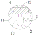
Fig. 2 is a partially enlarged view of a portion a in fig. 1.
Reference numbers in the figures: the device comprises a base plate 1, a connecting rod 2, a first spring 3, a supporting plate 4, a first support 5, a first shell 6, a second shell 7, a second support 8, a supporting column 9, a second spring 10, a sliding groove 11, a sliding block 12 and a moving block 13.
Detailed Description
The technical solutions in the embodiments of the present invention will be described clearly and completely with reference to the accompanying drawings in the embodiments of the present invention, and it is obvious that the described embodiments are only some embodiments of the present invention, not all embodiments.
Referring to fig. 1-2, a formula magnetic force actuation pump just tears open, including bottom plate 1 and backup pad 4, backup pad 4 is installed directly over bottom plate 1, the support column 9 of perpendicular setting is all welded to the both sides of the roof of bottom plate 1, backup pad 4 activity cup joints the outer lane at two support columns 9, be connected with two second springs 10 of perpendicular setting between the diapire of backup pad 4 and the roof of bottom plate 1, two second springs 10 are established respectively in the outer lane of two support columns 9, the intermediate position of the roof of bottom plate 1 articulates there are two connecting rods 2 that are the setting of V type, sliding connection has the movable block 13 that is two rectangles of symmetry setting on the diapire of backup pad 4, the top of two connecting rods 2 articulates respectively in the bottom of two movable blocks 13, be connected with the first spring 3 of level setting between two movable blocks 13.
In this embodiment, it has first support 5 and second support 8 to loop through the bolt fastening from left to right on the roof of backup pad 4, first casing 6 is welded on the top of first support 5, second casing 7 is welded on the top of second support 8, first casing 6 and second casing 7 pass through bolted connection, two spouts 11 have been seted up to the symmetry on the diapire of backup pad 4, it is provided with slider 12 to slide in spout 11, the bottom at two sliders 12 is fixed respectively to two movable blocks 13, two circular shape mounting holes have been seted up to the symmetry on bottom plate 1, two support columns 9 all are located between two mounting holes, the top of support column 9 extends to the top of backup pad 4 and the welding has the limiting plate.
Example (b): through the limiting function of the limiting plate, the supporting plate 4 can be prevented from being separated from the supporting column 9, the first shell 6 and the second shell 7 of the conveniently-disassembled magnetic driving pump main body are connected through bolts, and the first support 5 and the second support 8 are both fixed on the supporting plate 4 through bolts, so that the bolts used for fixing the first support 5 and the second support 8 are firstly taken down, and then the bolts used for connecting the first shell 6 and the second shell 7 are taken down, so that the disassembly of the shell of the conveniently-disassembled magnetic driving pump main body can be completed, the bottom plate 1 can be fixed on the ground through the bolts penetrating through the mounting holes, when the conveniently-disassembled magnetic driving pump main body runs, larger vibration can be generated, namely the lifting plate 4 can be continuously lifted, namely the second spring 10 can be continuously stretched, through the elastic potential energy action of the second spring 10, namely the supporting plate 4 can be rapidly returned, so that the vibration generated when the conveniently-disassembled magnetic driving pump main body runs can be preliminarily reduced, when backup pad 4 constantly goes up and down, can make two movable blocks 13 constantly go up and down, can make the top of two connecting rods 2 constantly be close to each other promptly, keep away from each other, can make two movable blocks 13 constantly be close to each other promptly, keep away from each other promptly, can make first spring 3 constantly flexible promptly, can make first spring 3 return rapidly, can make movable block 13 return rapidly promptly, can make backup pad 4 return rapidly promptly, thereby further reduce just the vibrations that produce when tearing open formula magnetic drive pump main part, through the vibrations that produce when effectual reduction just tears open formula magnetic drive pump main part, can prevent that just the internals of tearing open formula magnetic drive pump main part from damaging because of long-term vibrations by a wide margin, the utility model discloses the vibrations that produce during the operation are less, the internals is difficult to damage because of vibrations, and life is longer.
In the description of the present invention, it is to be understood that the terms "center", "longitudinal", "lateral", "length", "width", "thickness", "upper", "lower", "front", "rear", "left", "right", "vertical", "horizontal", "top", "bottom", "inner", "outer", "clockwise", "counterclockwise", and the like indicate orientations or positional relationships based on the orientations or positional relationships shown in the drawings, and are only for convenience of description and to simplify the description, but do not indicate or imply that the device or element referred to must have a particular orientation, be constructed and operated in a particular orientation, and therefore should not be construed as limiting the present invention.
Furthermore, the terms "first", "second" and "first" are used for descriptive purposes only and are not to be construed as indicating or implying relative importance or implicitly indicating the number of technical features indicated. Thus, a feature defined as "first" or "second" may explicitly or implicitly include one or more of that feature. In the description of the present invention, "a plurality" means two or more unless specifically limited otherwise.
The above, only be the concrete implementation of the preferred embodiment of the present invention, but the protection scope of the present invention is not limited thereto, and any person skilled in the art is in the technical scope of the present invention, according to the technical solution of the present invention and the utility model, the concept of which is equivalent to replace or change, should be covered within the protection scope of the present invention.
Claims (5)
1. The conveniently-disassembled magnetic drive pump comprises a bottom plate (1) and a support plate (4), and is characterized in that the support plate (4) is installed right above the bottom plate (1), support columns (9) which are vertically arranged are welded on two sides of the top wall of the bottom plate (1), the support plate (4) is movably sleeved on outer rings of the two support columns (9), two second springs (10) which are vertically arranged are connected between the bottom wall of the support plate (4) and the top wall of the bottom plate (1), the two second springs (10) are respectively sleeved on the outer rings of the two support columns (9), two connecting rods (2) which are V-shaped are hinged at the middle position of the top wall of the bottom plate (1), two rectangular moving blocks (13) which are symmetrically arranged are connected on the bottom wall of the support plate (4) in a sliding manner, and the top ends of the two connecting rods (2) are respectively hinged at the bottom ends of the two moving blocks (13), a first spring (3) which is horizontally arranged is connected between the two moving blocks (13).
2. The magnetic force driven pump convenient to detach is characterized in that a first support (5) and a second support (8) are fixed to the top wall of the supporting plate (4) sequentially from left to right through bolts, a first shell (6) is welded to the top end of the first support (5), a second shell (7) is welded to the top end of the second support (8), and the first shell (6) is connected with the second shell (7) through bolts.
3. The magnetic drive pump of claim 1, wherein the bottom wall of the support plate (4) is symmetrically provided with two sliding grooves (11), the sliding grooves (11) are provided with sliding blocks (12) in a sliding manner, and the two moving blocks (13) are respectively fixed at the bottom ends of the two sliding blocks (12).
4. The magnetic drive pump of claim 1, wherein the bottom plate (1) is symmetrically provided with two circular mounting holes, and the two support columns (9) are located between the two mounting holes.
5. A magnetic drive pump of the detachable type according to claim 1, wherein the top end of the supporting column (9) extends to the upper side of the supporting plate (4) and is welded with a limiting plate.
Priority Applications (1)
| Application Number | Priority Date | Filing Date | Title |
|---|---|---|---|
| CN201920935085.0U CN210152995U (en) | 2019-06-20 | 2019-06-20 | Conveniently-disassembled magnetic drive pump |
Applications Claiming Priority (1)
| Application Number | Priority Date | Filing Date | Title |
|---|---|---|---|
| CN201920935085.0U CN210152995U (en) | 2019-06-20 | 2019-06-20 | Conveniently-disassembled magnetic drive pump |
Publications (1)
| Publication Number | Publication Date |
|---|---|
| CN210152995U true CN210152995U (en) | 2020-03-17 |
Family
ID=69763597
Family Applications (1)
| Application Number | Title | Priority Date | Filing Date |
|---|---|---|---|
| CN201920935085.0U Expired - Fee Related CN210152995U (en) | 2019-06-20 | 2019-06-20 | Conveniently-disassembled magnetic drive pump |
Country Status (1)
| Country | Link |
|---|---|
| CN (1) | CN210152995U (en) |
-
2019
- 2019-06-20 CN CN201920935085.0U patent/CN210152995U/en not_active Expired - Fee Related
Similar Documents
| Publication | Publication Date | Title |
|---|---|---|
| CN109941710A (en) | A kind of rotating clamping device and operating method of engine cylinder body bayonet test | |
| CN210152995U (en) | Conveniently-disassembled magnetic drive pump | |
| CN219408920U (en) | Butt joint device for water pipeline | |
| CN220100021U (en) | An attachment quick-changing mechanism, working device and loader | |
| CN212927754U (en) | Hydraulic tong running gear in minor workover treatment equipment | |
| CN204739415U (en) | Segmentation high pressure rubber membrane canned type gas holder sealing device | |
| CN207596323U (en) | A kind of electric hydraulic pressure orange-peel bucket central cylinder | |
| CN211945809U (en) | A combined elevator guide rail | |
| CN207243386U (en) | Intelligent machine arm configuration | |
| CN207111403U (en) | A kind of outer casing stand of feed pump | |
| CN215254706U (en) | Adjustable lifting appliance for constructional engineering construction | |
| CN212076140U (en) | Organism hoisting frame convenient to fix hanger arm | |
| CN210621550U (en) | Lifting column not easy to be damaged by collision | |
| CN217203674U (en) | Box culvert pipeline installation structure penetrating through flood discharge tunnel | |
| CN212175463U (en) | A kind of bridge pier support steel structure reinforcement device | |
| CN204384827U (en) | Suspension type jacking transferring device | |
| CN222066661U (en) | Detachable carriage body bracket of drilling machine | |
| CN223507657U (en) | Flexible anti-rotation mechanism of bottle blowing machine | |
| CN216920504U (en) | Bottom silt dredging device for river channel treatment engineering | |
| CN222494071U (en) | Walking wheel replacement tool applied to bucket wheel machine | |
| CN212824971U (en) | Special clamping device for fragile object | |
| CN209985390U (en) | Clindamycin hydrochloride reaction unit with safety protection function | |
| CN211731477U (en) | Transfer device of barrel plating machine | |
| CN205874949U (en) | Landing stage device based on from walking | |
| CN2670449Y (en) | Big and small arms of small digging machine |
Legal Events
| Date | Code | Title | Description |
|---|---|---|---|
| GR01 | Patent grant | ||
| GR01 | Patent grant | ||
| CF01 | Termination of patent right due to non-payment of annual fee | ||
| CF01 | Termination of patent right due to non-payment of annual fee |
Granted publication date: 20200317 |