SUMMERY OF THE UTILITY MODEL
A primary object of the utility model is to provide a remote control is controlling means and switch module disconnected a little to solve the power among the prior art and open the problem that the maloperation probability is big, the potential safety hazard is high.
In order to achieve the above object, according to an aspect of the present invention, there is provided a remote control micro-break control device, comprising: a housing; the opening and closing push rod is movably arranged on the shell and is provided with a handle accommodating part for accommodating an air opening handle; the electric driving assembly is arranged in the shell and comprises a driving part, a belt wheel assembly and a reset detection/connection part, the belt wheel assembly is in driving connection with the driving part, the reset detection/connection part is arranged on the belt wheel assembly, and the reset detection/connection part rotates along with the belt wheel assembly to enable the belt wheel assembly to reset or be in driving connection with the opening and closing push rod; and the driving part drives the belt wheel assembly to reset after being triggered by the control assembly, then drives the reset detection/connection part to drive the opening and closing push rod to move, and at the moment, the remote control micro-breaking control device is in a remote control mode.
Further, the driving part includes a driving motor; the pulley assembly includes: the device comprises a driving belt wheel, a synchronous belt and a driven belt wheel, wherein the driving belt wheel is sleeved on an output shaft of a driving motor, the driving belt wheel and the driven belt wheel are arranged at two ends of a motion trail of a split-joint push rod in a coplanar mode, the synchronous belt is respectively meshed with the driving belt wheel and the driven belt wheel, and the reset detection/connection part is fixed on the synchronous belt.
Furthermore, the remote control micro-breaking control device also comprises a manual mode; the control assembly includes: the mode switching module is used for switching the remote control micro-break control device between the remote control mode or the manual mode.
Further, the mode switching module comprises a switch for triggering the control component, a yielding hole is formed in the shell, and the switch penetrates out of the yielding hole.
Further, the control assembly further comprises: and the position detection module is used for detecting the positions of the belt wheel assembly and the opening and closing push rod.
Further, the mode switching module includes a switch for triggering the control assembly, and the position detecting module includes: a first microswitch located outside of the pulley assembly; the second microswitch is positioned at the bottom of the opening and closing push rod; when the control component is triggered by the change-over switch, the remote control micro-break control device performs initialization operation: when the opening and closing push rod triggers the second microswitch, the opening and closing push rod is positioned at a separating position, and at the moment, the driving motor is enabled to rotate forwards or backwards so that the reset detection/connection part triggers the first microswitch, and the belt wheel assembly completes resetting; when the second micro switch is in an unfired state, the opening and closing push rod is located at a closed position, at the moment, the driving motor rotates forwards or backwards to enable the opening and closing push rod to trigger the second micro switch, so that the opening and closing push rod is located at a separated position, then the reset detection/connection part is driven to trigger the first micro switch, and the belt wheel assembly is enabled to complete reset.
Further, divide closing push rod still includes the hold-in range portion of holding, the hold-in range of band pulley assembly wears to establish in the hold-in range portion of holding.
Further, the opening/closing push rod includes: a main body on which the handle accommodating part is provided; the connecting block is arranged on the main body and provided with a groove; the push rod cover is arranged on the groove and surrounds the groove to form the synchronous belt accommodating part.
Furthermore, two opposite sides of the main body are provided with sliding parts; the shell is provided with a first strip hole and a pressing plate, the pressing plate is arranged on two side edges of the first strip hole and forms a sliding groove with the shell, the main body penetrates out of the shell from the first strip hole, and the sliding part is located in the sliding groove.
Furthermore, a second strip hole is formed in the shell, and the push rod cover penetrates out of the shell from the second strip hole.
Furthermore, the reset detection/connection part is provided with a first matching surface and a second matching surface, and the first matching surface and the second matching surface are respectively positioned at two opposite sides of the reset detection/connection part; the split-combination push rod further comprises a first limiting surface and a second limiting surface, the first limiting surface is positioned at the bottom of the split-combination push rod, and the second limiting surface is positioned at the top of the split-combination push rod; when the second matching surface is matched with the second limiting surface and drives the dividing and combining push rod to push downwards, the dividing and combining push rod is switched from the combining position to the combining position.
According to the utility model discloses an on the other hand provides a switch module, including air switch and the little disconnected controlling means of remote control, the remote control slightly disconnected controlling means's handle holding portion with air switch's empty handle is opened and is connected, the remote control slightly disconnected controlling means is foretell remote control slightly disconnected controlling means.
Use the technical scheme of the utility model, the during operation, through control assembly's effect, can make the remote control slightly break controlling means select to adopt manual mode or remote control mode work, when the remote control slightly breaks controlling means and is in remote control mode, the drive division drives the band pulley subassembly after the control assembly triggers and resets, then drives the detection/connecting portion that resets and drive the deciliter push rod motion, and then drives the deciliter push rod and drive the motion of air switch handle and carry out the switching to air switch.
The utility model provides a little disconnected controlling means of remote control can be applicable to the problem of the unable remote control operation of equipment power sky such as circuit breaker in the transformer substation, isolation switch, ground connection switch, through the effect of little disconnected controlling means's of remote control electrical drive assembly, can realize that the long-range of the interior power sky of transformer substation opens and moves back, can make the deciliter push rod switch between remote control mode and manual mode, and detachable installs on air switch, effectively improve the accuracy and the factor of safety of the air switch handle deciliter operation on the air switch.
Detailed Description
It should be noted that the embodiments and features of the embodiments in the present application may be combined with each other without conflict. The present invention will be described in detail below with reference to the accompanying drawings in conjunction with embodiments.
It is noted that the terminology used herein is for the purpose of describing particular embodiments only and is not intended to be limiting of example embodiments according to the present application. As used herein, the singular forms "a", "an" and "the" are intended to include the plural forms as well, and it should be understood that when the terms "comprises" and/or "comprising" are used in this specification, they specify the presence of stated features, steps, operations, devices, components, and/or combinations thereof, unless the context clearly indicates otherwise.
Spatially relative terms, such as "above … …," "above … …," "above … …," "above," and the like, may be used herein for ease of description to describe one device or feature's spatial relationship to another device or feature as illustrated in the figures. It will be understood that the spatially relative terms are intended to encompass different orientations of the device in use or operation in addition to the orientation depicted in the figures. For example, if a device in the figures is turned over, devices described as "above" or "on" other devices or configurations would then be oriented "below" or "under" the other devices or configurations. Thus, the exemplary term "above … …" can include both an orientation of "above … …" and "below … …". The device may be otherwise variously oriented (rotated 90 degrees or at other orientations) and the spatially relative descriptors used herein interpreted accordingly.
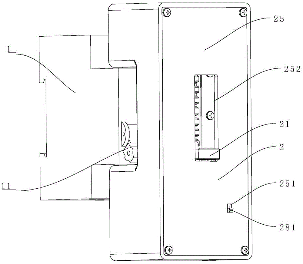
Referring to fig. 1 to 10, according to an embodiment of the present invention, there is provided a switch assembly including an air switch 1 and a remote control micro-break control device 2.
In actual installation, the remote control micro-break control device 2 is installed on the air switch 1, and specifically, the remote control micro-break control device 2 includes a housing 25, a switching push rod 21, an electric drive unit, and a control unit 28.
The opening and closing push rod 21 is movably mounted on the housing 25, and a handle accommodating part 212 for accommodating the air switch handle 11 is arranged on the opening and closing push rod 21, so that the air switch 1 can be conveniently coupled with the air switch handle 11 to drive the air switch handle 11 to move so as to open and close the air switch; an electrical drive assembly is mounted within housing 25 and includes a drive portion, a pulley assembly drivingly connected to the drive portion and a reset detection/connection portion 231, the reset detection/connection portion 231 being disposed on the pulley assembly during actual installation.
When the device works, the reset detection/connection part 231 rotates along with the belt wheel component to reset the belt wheel component or is in driving connection with the opening and closing push rod 21; the control assembly 28 is in communication connection with the electric drive assembly, during actual work, the remote control micro-breaking control device 2 has a remote control mode and a manual mode, when the drive portion is triggered by the control assembly 28, the drive portion drives the belt wheel assembly to reset, then the reset detection/connection portion 231 is driven to drive the separation and combination push rod 21 to move, and at the moment, the remote control micro-breaking control device 2 is in the remote control mode.
During actual work, through the effect of control assembly 28, can make remote control slight break controlling means 2 select to adopt manual mode or remote control mode work, when remote control slight break controlling means 2 was in the remote control mode, the drive division is driven the band pulley subassembly and is reset after being triggered by control assembly 28, then drives again and resets detection/connecting portion 231 and drive deciliter push rod 21 motion, and then drives deciliter push rod 21 and drives the motion of air switch handle 11 and carry out the switching to air switch 1.
The remote control micro-breaking control device 2 in the embodiment can be suitable for the problem that the power supply of equipment such as a circuit breaker, an isolation switch and a grounding switch in a transformer substation cannot be remotely controlled, the remote switching-on and switching-off of the power supply in the transformer substation can be realized under the action of the electric drive assembly of the remote control micro-breaking control device 2, the switching-on and switching-off push rod 21 can be switched between a remote control mode and a manual mode, the switching-on and switching-off push rod is detachably mounted on the air switch 1, and the accuracy and the safety factor of the switching-on and switching-off operation of the air switch handle 11 on the air.
Specifically, the driving section in the present embodiment includes a driving motor 27; the pulley assembly includes a drive pulley 26, a timing belt 23 and a driven pulley 24.
During installation, the driving pulley 26 is sleeved on the output shaft of the driving motor 27, the driven pulley 24 is installed in the housing 25 through the rotating shaft 242, the driving pulley 26 and the driven pulley 24 are coplanar and arranged at two ends of the motion track of the opening and closing push rod 21 and parallel to the motion track of the opening and closing push rod 21, the synchronous belt 23 is respectively meshed with the driving pulley 26 and the driven pulley 24, the inner side of the synchronous belt 23 is provided with a tooth-shaped structure 232 which is meshed with the tooth-shaped structures of the driving pulley 26 and the driven pulley 24 and can perform synchronous motion under the driving of the driving motor 27, the rotating motion of the driving motor 27 can be converted into synchronous belt 23 transmission, the reset detection/connection part 231 is fixed on the synchronous belt 23 and can be used for pushing the opening and closing push rod 21 to perform linear reciprocating motion, and further driving the air. The driving motor 27 is fixedly mounted in the housing 25 by screws and is coaxially disposed with the driving pulley 26, and the driving pulley 26 is engaged with an output shaft of the driving motor 27 by means of a D-shaped groove or interference, and can transmit a driving force.
Deciliter push rod 21 still includes hold-in range holding portion 213, and the hold-in range 23 of pulley assembly wears to establish in hold-in range holding portion 213, and with hold-in range 23 clearance fit, hold-in range 23 can be placed in hold-in range holding portion 213 to slide, prevent that hold-in range 23 from deviating from in deciliter push rod 21.
Referring to fig. 2 to 10, the opening/closing push rod 21 in the present embodiment includes a main body 217, a connecting block 218, and a push rod cover 211, wherein a handle accommodating portion 212 is provided on the main body 217; the connecting block 218 is arranged on the main body 217, and a groove 219 is formed in the connecting block 218, so that the synchronous belt 23 can be conveniently installed in the groove 219; the push rod cover 211 covers the groove 219 and surrounds the groove 219 to form a timing belt accommodating portion 213, which prevents the timing belt 23 from coming off from the switching push rod 21 and can be used as a push portion in the manual mode.
In order to facilitate the sliding of the opening and closing push rod 21, the two opposite sides of the main body 217 in the embodiment are provided with sliding parts 216; correspondingly, the housing 25 is provided with a first elongated hole (not shown) and a pressing plate 22, the pressing plate 22 is disposed at two sides of the first elongated hole and forms a sliding slot with the housing 25, when the device is installed, the main body 217 penetrates out of the housing 25 from the first elongated hole to couple with the free handle 11, and the sliding portion 216 is located in the sliding slot to facilitate a linear reciprocating motion along the sliding slot under the pushing of the reset detecting/connecting portion 231.
The pressing plate 22 is of a long plate-shaped structure, is fixedly installed in the shell 25 through a screw after the opening and closing push rod 21 is installed in the first long hole of the push rod of the shell 25, and forms a sliding groove with the shell 25 outside the first long hole to limit the motion track of the opening and closing push rod 21 in the remote control micro-breaking control device 2.
Preferably, the reset detecting/connecting portion 231 in this embodiment is a bump, which is simple in structure and easy to implement. The reset detection/connection portion 231 has a first mating surface 2311 and a second mating surface 2312, and the first mating surface 2311 and the second mating surface 2312 are respectively located at two opposite sides of the reset detection/connection portion 231; correspondingly, the opening and closing push rod 21 further comprises a first limiting surface 214 and a second limiting surface 215, the first limiting surface 214 is located at the bottom of the opening and closing push rod 21, and the second limiting surface 215 is located at the top of the opening and closing push rod 21.
In actual work, when the first matching surface 2311 is matched with the first limiting surface 214 and drives the opening and closing push rod 21 to push upwards, the opening and closing push rod 21 is switched from the open position to the closed position, and when the second matching surface 2312 is matched with the second limiting surface 215 and drives the opening and closing push rod 21 to push downwards, the opening and closing push rod 21 is switched from the closed position to the open position.
The housing 25 in this embodiment includes a main body and a cover plate, the cover plate is fixed to the main body by screws, and the housing 25 has a push rod mounting part, a drive train mounting part, a control module mounting part and a fixing structure therein, for fixing and accommodating parts of the remote control micro-break control device 2, and has integrity, aesthetic property and dustproof function.
Referring again to fig. 2-10, the control assembly 28 in this embodiment includes a mode switching module, a position detection module, an appliance control module, and a communication module.
The mode switching module is used for switching the remote control micro-break control device 2 between a remote control mode or a manual mode. The mode switching module includes a switch 281 for triggering the control unit 28, and the switching between the manual mode and the remote control mode can be accomplished by moving the switch 281. In order to facilitate the operation, the housing 25 in this embodiment is provided with a relief hole 251, and the switch 281 penetrates out of the housing 25 through the relief hole 251, preferably, the relief hole 251 is provided on a cover plate, so that an operator can operate the switch 281 conveniently.
The position detection module is used for detecting the positions of the pulley assembly and the opening and closing push rod 21. The position detection module comprises a first microswitch 282 and a second microswitch 283, wherein the first microswitch 282 is positioned at the outer side of the belt wheel assembly, namely the non-transmission side of the synchronous belt 23, and the first microswitch 282 can detect whether the reset detection/connection part 231 on the synchronous belt 23 is positioned at the zero position of the synchronous belt 23; the second microswitch 283 is positioned at the bottom of the opening and closing push rod 21; whether the opening and closing push rod 21 is located at the initial position, that is, the opening and closing push rod 21 is located at the separate position can be detected.
Specifically, when the changeover switch 281 triggers the control unit 28, the remote control micro-break control device 2 performs an initialization operation, and when the switching push rod 21 triggers the second micro switch 283 at the time of the initialization operation of the remote control micro-break control device 2, the switching push rod 21 is positioned at the off position, and at this time, the driving motor 27 is rotated forward or backward so that the reset detection/connection unit 231 triggers the first micro switch 282, and the pulley unit is reset. Specifically, when the second microswitch 283 is triggered by the opening and closing push rod 21, the driving motor 27 rotates for a certain time towards the direction far away from the separating position, and when the first microswitch 282 is triggered by the reset detection/connection part 231 of the synchronous belt 23, the driving motor is powered off, and the synchronous belt is located at the zero position of the belt; when the trigger signal of the first microswitch 282 is not detected within the set time, the driving motor 27 rotates in the reverse direction for a certain time, and when the trigger of the first microswitch is detected, the rotation is stopped, and the belt is located at the zero position.
When the second micro switch 283 is in an un-triggered state, the opening and closing push rod 21 is located at the closing position, at this time, the driving motor 27 rotates clockwise or counterclockwise to make the opening and closing push rod 21 trigger the second micro switch 283, and then the reset detection/connection part 231 is driven to trigger the first micro switch 282, so that the belt wheel assembly is reset.
The control assembly 28 further includes a control board 284, the control board 284 being communicatively coupled to the electrical drive assembly to facilitate control of the electrical drive assembly.
Preferably, the housing 25 is provided with a second elongated hole 252, and the push rod cover 211 penetrates out of the housing 25 through the second elongated hole 252, so that an operator can conveniently perform manual operation on the split push rod 21.
In the remote control mode, the switch 281 is shifted to an on state, the reset detection/connection part 231 is located at the zero position of the belt, the motor 27 can be driven to rotate in a remote control mode to drive the synchronous belt 23 to rotate, the first matching surface 2311 and the second matching surface 2312 of the reset detection/connection part 231 push the first limiting surface 214 or the second limiting surface 215 of the opening and closing push rod 21 to linearly move after rotating for a certain time, and the air opening handle 11 is driven to perform the opening and closing operation of the air switch;
during manual operation, the switch 281 is shifted to a closed state, the reset detection/connection part 231 is located at the initial position of the synchronous belt 23 and is far away from the first limit surface 214 or the second limit surface 215 of the opening and closing push rod 21, the driving motor 27 is not electrified, and the opening and closing push rod 21 can be manually operated to drive the air opening handle 11 to perform opening and closing operations.
Referring again to fig. 1 to 10, the operating principle of the switch assembly in the present application is as follows:
the initialization principle is as follows:
when the remote control micro-break control device 2 is put into operation, the state of the second micro-switch 283 is detected: when the second microswitch 283 is detected to be in a trigger state, the opening and closing push rod 21 is positioned at the opening position, and the driving motor 27 rotates clockwise for a set time; when the reset detection/connection part 231 is detected to trigger the first microswitch 282, the driving motor 27 is powered off, and the synchronous belt 23 is located at the initial position; when the trigger signal of the first microswitch 282 is not detected within the set time, the driving motor 27 rotates counterclockwise for the set time, when the trigger of the first microswitch 282 is detected, the driving motor 27 stops rotating, and the synchronous belt 23 is located at the initial position; when the second micro switch 283 is in an un-triggered state, the opening and closing push rod 21 is located at the closed position, at this time, the driving motor 27 rotates clockwise or counterclockwise to make the opening and closing push rod 21 trigger the second micro switch 283, and then the reset detection/connection part 231 is driven to trigger the first micro switch 282, so that the belt wheel assembly is reset, as shown in fig. 3 and 4.
Remote control principle:
initial position division:
the switch 281 is pushed up to switch to the remote control mode, the remote control micro-break control device 2 performs the initialization operation, and after the initialization operation is completed, the reset detection/connection unit 231 is located at the initial position, and at this time, the remote control micro-break control device 2 waits for the remote control information, as shown in fig. 6.
From open to closed:
after receiving the remote control closing command, the driving motor 27 rotates for a predetermined time to drive the driving pulley 26 to rotate counterclockwise, so as to drive the synchronous belt 23 to rotate counterclockwise, when the first mating surface 2311 of the reset detection/connection portion 231 rotates to the first limiting surface 214 of the opening and closing push rod 21, the opening and closing push rod 21 is pushed to move to the closed position under the driving of the driving force, and at this time, the handle accommodating portion 212 of the opening and closing push rod 21 pushes the air switch 1 to move from the open position to the closed position, as shown in fig. 7.
After the closing position is reached, the driving motor 27 rotates clockwise, the first mating surface 2311 of the reset detection/connection part 231 is separated from the first limiting surface 214 of the opening and closing push rod 21, and under the action of the driving force, the reset detection/connection part 231 moves to the triggering position of the first micro switch 282, namely the initial position of the synchronous belt 23, the driving motor 27 stops rotating, at the moment, the reset detection/connection part 231 is separated from the opening and closing push rod 21, and the automatic tripping or manual operation of the air switch 1 in the use process is not influenced, as shown in fig. 8.
From closed to open:
after receiving the remote control positioning command, the driving motor 27 rotates for a predetermined time to drive the driving pulley 26 to rotate clockwise, so as to drive the synchronous belt 23 to rotate clockwise, when the second matching surface 2312 of the reset detection/connection portion 231 rotates to the second limiting surface 215 of the opening and closing push rod 21, the opening and closing push rod 21 is pushed to move to the positioning position under the driving of the driving force, and at this time, the opening and closing push rod handle accommodating portion 212 pushes the air switch 1 to move from the positioning position to the closing position, as shown in fig. 9.
After reaching the separating position, the driving motor 27 rotates counterclockwise, the second mating surface 2312 of the reset detection/connection portion 231 is separated from the second limiting surface 215 of the opening and closing push rod 21, and under the action of the driving force, when the reset detection/connection portion 231 moves to the triggering position of the first micro switch 282, namely the initial position of the synchronous belt 23, the driving motor 27 stops rotating, and at this time, the reset detection/connection portion 231 is separated from the opening and closing push rod 21, so that the automatic tripping or manual operation of the air switch 1 in the use process is not influenced, as shown in fig. 6.
The manual operation principle is as follows:
the switch 281 is pushed downward to switch to the manual mode, the remote control micro-breaking control device 2 performs an initialization operation, after the initialization operation is completed, the reset detection/connection part 231 is located at the initial position of the synchronous belt 23 and is far away from the first limit surface 214 or the second limit surface 215 of the opening and closing push rod 21, as shown in fig. 4, the driving motor 27 is powered off, and the manual operation can be performed. The operator pushes the opening and closing push rod 21 upwards to push the opening and closing push rod 21 to do linear motion in the chute, and the lower end of the opening and closing push rod can drive the air opening handle 11 to move from the open position to the closed position. The operator pushes the opening and closing push rod 21 downwards to push the opening and closing push rod 21 to make a linear motion in the chute, and the lower end of the opening and closing push rod can drive the air opening handle 11 to move from a closed position to an open position, as shown in fig. 5 and 6.
From the above description, it can be seen that the above-mentioned embodiments of the present invention achieve the following technical effects: the invention provides a remote switching-on/off remote control micro-breaking control device for a power supply air switch in a transformer substation, which has the functions of local manual operation, remote control operation and mode switching. Under the prerequisite that does not influence the existing function of air switch, increased electric control mechanism, effectively improved the intelligent mistake management level of preventing of air switch. The problem of the remote control operation of the disconnecting link operation power supply and the motor power supply is solved, and the accidents of self-separation, self-closing or mistaken touch separation and closing and the like when the equipment is in a charged state for a long time can be prevented.
It should be noted that the terms "first," "second," and the like in the description and claims of this application and in the drawings described above are used for distinguishing between similar elements and not necessarily for describing a particular sequential or chronological order. It is to be understood that the data so used is interchangeable under appropriate circumstances such that the embodiments of the application described herein are, for example, capable of operation in sequences other than those illustrated or otherwise described herein. Furthermore, the terms "comprises," "comprising," and "having," and any variations thereof, are intended to cover a non-exclusive inclusion, such that a process, method, system, article, or apparatus that comprises a list of steps or elements is not necessarily limited to those steps or elements expressly listed, but may include other steps or elements not expressly listed or inherent to such process, method, article, or apparatus.
The above is only a preferred embodiment of the present invention, and is not intended to limit the present invention, and various modifications and changes will occur to those skilled in the art. Any modification, equivalent replacement, or improvement made within the spirit and principle of the present invention should be included in the protection scope of the present invention.