CN210340645U - Sludge recycling treatment system - Google Patents
Sludge recycling treatment system Download PDFInfo
- Publication number
- CN210340645U CN210340645U CN201921176188.XU CN201921176188U CN210340645U CN 210340645 U CN210340645 U CN 210340645U CN 201921176188 U CN201921176188 U CN 201921176188U CN 210340645 U CN210340645 U CN 210340645U
- Authority
- CN
- China
- Prior art keywords
- sludge
- flash tank
- recycling
- treatment system
- tank
- Prior art date
- Legal status (The legal status is an assumption and is not a legal conclusion. Google has not performed a legal analysis and makes no representation as to the accuracy of the status listed.)
- Active
Links
- 239000010802 sludge Substances 0.000 title claims abstract description 147
- 238000004064 recycling Methods 0.000 title claims abstract description 40
- 238000001179 sorption measurement Methods 0.000 claims abstract description 57
- 229910001385 heavy metal Inorganic materials 0.000 claims abstract description 29
- 239000007788 liquid Substances 0.000 claims abstract description 16
- OKTJSMMVPCPJKN-UHFFFAOYSA-N Carbon Chemical compound [C] OKTJSMMVPCPJKN-UHFFFAOYSA-N 0.000 claims description 69
- 238000006460 hydrolysis reaction Methods 0.000 claims description 28
- XLYOFNOQVPJJNP-UHFFFAOYSA-N water Substances O XLYOFNOQVPJJNP-UHFFFAOYSA-N 0.000 claims description 21
- 238000000926 separation method Methods 0.000 claims description 18
- 238000002156 mixing Methods 0.000 claims description 15
- 238000010438 heat treatment Methods 0.000 claims description 13
- 239000002912 waste gas Substances 0.000 claims description 13
- 230000003750 conditioning effect Effects 0.000 claims description 12
- 239000003337 fertilizer Substances 0.000 claims description 12
- 239000003516 soil conditioner Substances 0.000 claims description 12
- ZLMJMSJWJFRBEC-UHFFFAOYSA-N Potassium Chemical compound [K] ZLMJMSJWJFRBEC-UHFFFAOYSA-N 0.000 claims description 9
- 239000011591 potassium Substances 0.000 claims description 9
- 229910052700 potassium Inorganic materials 0.000 claims description 9
- 239000002367 phosphate rock Substances 0.000 claims description 4
- 102000004169 proteins and genes Human genes 0.000 claims description 3
- 108090000623 proteins and genes Proteins 0.000 claims description 3
- 238000000034 method Methods 0.000 abstract description 12
- 230000008569 process Effects 0.000 abstract description 6
- 230000009467 reduction Effects 0.000 abstract description 2
- 230000007062 hydrolysis Effects 0.000 description 15
- 239000003795 chemical substances by application Substances 0.000 description 14
- 239000002689 soil Substances 0.000 description 13
- 230000003301 hydrolyzing effect Effects 0.000 description 12
- 239000005416 organic matter Substances 0.000 description 11
- 239000012460 protein solution Substances 0.000 description 8
- 238000010586 diagram Methods 0.000 description 7
- 238000009434 installation Methods 0.000 description 7
- 239000000243 solution Substances 0.000 description 7
- 238000005516 engineering process Methods 0.000 description 5
- 230000006872 improvement Effects 0.000 description 5
- 230000001105 regulatory effect Effects 0.000 description 5
- 230000002378 acidificating effect Effects 0.000 description 4
- 230000008901 benefit Effects 0.000 description 4
- 238000009264 composting Methods 0.000 description 4
- 239000012528 membrane Substances 0.000 description 4
- 230000004048 modification Effects 0.000 description 4
- 238000012986 modification Methods 0.000 description 4
- 238000012545 processing Methods 0.000 description 4
- 239000010865 sewage Substances 0.000 description 4
- PUKLDDOGISCFCP-JSQCKWNTSA-N 21-Deoxycortisone Chemical compound C1CC2=CC(=O)CC[C@]2(C)[C@@H]2[C@@H]1[C@@H]1CC[C@@](C(=O)C)(O)[C@@]1(C)CC2=O PUKLDDOGISCFCP-JSQCKWNTSA-N 0.000 description 3
- FCYKAQOGGFGCMD-UHFFFAOYSA-N Fulvic acid Natural products O1C2=CC(O)=C(O)C(C(O)=O)=C2C(=O)C2=C1CC(C)(O)OC2 FCYKAQOGGFGCMD-UHFFFAOYSA-N 0.000 description 3
- HEMHJVSKTPXQMS-UHFFFAOYSA-M Sodium hydroxide Chemical compound [OH-].[Na+] HEMHJVSKTPXQMS-UHFFFAOYSA-M 0.000 description 3
- 230000007613 environmental effect Effects 0.000 description 3
- 239000002509 fulvic acid Substances 0.000 description 3
- 229940095100 fulvic acid Drugs 0.000 description 3
- 125000000524 functional group Chemical group 0.000 description 3
- 239000000463 material Substances 0.000 description 3
- 244000005700 microbiome Species 0.000 description 3
- 239000000203 mixture Substances 0.000 description 3
- 235000015097 nutrients Nutrition 0.000 description 3
- 244000052769 pathogen Species 0.000 description 3
- 239000000843 powder Substances 0.000 description 3
- IJGRMHOSHXDMSA-UHFFFAOYSA-N Atomic nitrogen Chemical compound N#N IJGRMHOSHXDMSA-UHFFFAOYSA-N 0.000 description 2
- 208000005156 Dehydration Diseases 0.000 description 2
- XLYOFNOQVPJJNP-ZSJDYOACSA-N Heavy water Chemical compound [2H]O[2H] XLYOFNOQVPJJNP-ZSJDYOACSA-N 0.000 description 2
- 239000003513 alkali Substances 0.000 description 2
- 239000002956 ash Substances 0.000 description 2
- 244000052616 bacterial pathogen Species 0.000 description 2
- 230000015556 catabolic process Effects 0.000 description 2
- 210000002421 cell wall Anatomy 0.000 description 2
- 238000004891 communication Methods 0.000 description 2
- 238000006731 degradation reaction Methods 0.000 description 2
- 230000018044 dehydration Effects 0.000 description 2
- 238000006297 dehydration reaction Methods 0.000 description 2
- 238000011161 development Methods 0.000 description 2
- 230000018109 developmental process Effects 0.000 description 2
- 238000001704 evaporation Methods 0.000 description 2
- 230000008020 evaporation Effects 0.000 description 2
- 239000007789 gas Substances 0.000 description 2
- 238000002715 modification method Methods 0.000 description 2
- BWHMMNNQKKPAPP-UHFFFAOYSA-L potassium carbonate Chemical compound [K+].[K+].[O-]C([O-])=O BWHMMNNQKKPAPP-UHFFFAOYSA-L 0.000 description 2
- 230000008929 regeneration Effects 0.000 description 2
- 238000011069 regeneration method Methods 0.000 description 2
- 239000000126 substance Substances 0.000 description 2
- DLYUQMMRRRQYAE-UHFFFAOYSA-N tetraphosphorus decaoxide Chemical compound O1P(O2)(=O)OP3(=O)OP1(=O)OP2(=O)O3 DLYUQMMRRRQYAE-UHFFFAOYSA-N 0.000 description 2
- QGZKDVFQNNGYKY-UHFFFAOYSA-N Ammonia Chemical compound N QGZKDVFQNNGYKY-UHFFFAOYSA-N 0.000 description 1
- 241000894006 Bacteria Species 0.000 description 1
- 239000002028 Biomass Substances 0.000 description 1
- RWSOTUBLDIXVET-UHFFFAOYSA-N Dihydrogen sulfide Chemical compound S RWSOTUBLDIXVET-UHFFFAOYSA-N 0.000 description 1
- 230000001133 acceleration Effects 0.000 description 1
- 239000002253 acid Substances 0.000 description 1
- 238000012271 agricultural production Methods 0.000 description 1
- 238000005576 amination reaction Methods 0.000 description 1
- BFNBIHQBYMNNAN-UHFFFAOYSA-N ammonium sulfate Chemical compound N.N.OS(O)(=O)=O BFNBIHQBYMNNAN-UHFFFAOYSA-N 0.000 description 1
- 229910052921 ammonium sulfate Inorganic materials 0.000 description 1
- 235000011130 ammonium sulphate Nutrition 0.000 description 1
- QVGXLLKOCUKJST-UHFFFAOYSA-N atomic oxygen Chemical compound [O] QVGXLLKOCUKJST-UHFFFAOYSA-N 0.000 description 1
- 230000001580 bacterial effect Effects 0.000 description 1
- 230000009286 beneficial effect Effects 0.000 description 1
- 239000011449 brick Substances 0.000 description 1
- AXCZMVOFGPJBDE-UHFFFAOYSA-L calcium dihydroxide Chemical compound [OH-].[OH-].[Ca+2] AXCZMVOFGPJBDE-UHFFFAOYSA-L 0.000 description 1
- 239000000920 calcium hydroxide Substances 0.000 description 1
- 229910001861 calcium hydroxide Inorganic materials 0.000 description 1
- BRPQOXSCLDDYGP-UHFFFAOYSA-N calcium oxide Chemical compound [O-2].[Ca+2] BRPQOXSCLDDYGP-UHFFFAOYSA-N 0.000 description 1
- 239000000292 calcium oxide Substances 0.000 description 1
- ODINCKMPIJJUCX-UHFFFAOYSA-N calcium oxide Inorganic materials [Ca]=O ODINCKMPIJJUCX-UHFFFAOYSA-N 0.000 description 1
- KMQAPZBMEMMKSS-UHFFFAOYSA-K calcium;magnesium;phosphate Chemical compound [Mg+2].[Ca+2].[O-]P([O-])([O-])=O KMQAPZBMEMMKSS-UHFFFAOYSA-K 0.000 description 1
- YYRMJZQKEFZXMX-UHFFFAOYSA-N calcium;phosphoric acid Chemical compound [Ca+2].OP(O)(O)=O.OP(O)(O)=O YYRMJZQKEFZXMX-UHFFFAOYSA-N 0.000 description 1
- 238000006243 chemical reaction Methods 0.000 description 1
- 238000010276 construction Methods 0.000 description 1
- 230000029087 digestion Effects 0.000 description 1
- 238000001035 drying Methods 0.000 description 1
- 238000005265 energy consumption Methods 0.000 description 1
- 230000002349 favourable effect Effects 0.000 description 1
- 239000010881 fly ash Substances 0.000 description 1
- 239000002920 hazardous waste Substances 0.000 description 1
- 229910000037 hydrogen sulfide Inorganic materials 0.000 description 1
- 230000010354 integration Effects 0.000 description 1
- 230000003993 interaction Effects 0.000 description 1
- 238000004519 manufacturing process Methods 0.000 description 1
- 239000011159 matrix material Substances 0.000 description 1
- 239000000693 micelle Substances 0.000 description 1
- 238000005065 mining Methods 0.000 description 1
- 229910000402 monopotassium phosphate Inorganic materials 0.000 description 1
- 235000019796 monopotassium phosphate Nutrition 0.000 description 1
- 229910052757 nitrogen Inorganic materials 0.000 description 1
- 235000021049 nutrient content Nutrition 0.000 description 1
- 239000001301 oxygen Substances 0.000 description 1
- 229910052760 oxygen Inorganic materials 0.000 description 1
- 231100001239 persistent pollutant Toxicity 0.000 description 1
- PJNZPQUBCPKICU-UHFFFAOYSA-N phosphoric acid;potassium Chemical compound [K].OP(O)(O)=O PJNZPQUBCPKICU-UHFFFAOYSA-N 0.000 description 1
- 229910000027 potassium carbonate Inorganic materials 0.000 description 1
- CHWRSCGUEQEHOH-UHFFFAOYSA-N potassium oxide Chemical compound [O-2].[K+].[K+] CHWRSCGUEQEHOH-UHFFFAOYSA-N 0.000 description 1
- 229910001950 potassium oxide Inorganic materials 0.000 description 1
- 238000010248 power generation Methods 0.000 description 1
- 238000007781 pre-processing Methods 0.000 description 1
- 239000002994 raw material Substances 0.000 description 1
- 230000035484 reaction time Effects 0.000 description 1
- 238000010992 reflux Methods 0.000 description 1
- 238000009287 sand filtration Methods 0.000 description 1
- 229920006395 saturated elastomer Polymers 0.000 description 1
- 239000002002 slurry Substances 0.000 description 1
- 239000002364 soil amendment Substances 0.000 description 1
- 230000006641 stabilisation Effects 0.000 description 1
- 238000011105 stabilization Methods 0.000 description 1
- 229910001220 stainless steel Inorganic materials 0.000 description 1
- 239000010935 stainless steel Substances 0.000 description 1
- 238000003756 stirring Methods 0.000 description 1
- QAOWNCQODCNURD-UHFFFAOYSA-N sulfuric acid Substances OS(O)(=O)=O QAOWNCQODCNURD-UHFFFAOYSA-N 0.000 description 1
- 239000002426 superphosphate Substances 0.000 description 1
- 238000009423 ventilation Methods 0.000 description 1
- 239000002918 waste heat Substances 0.000 description 1
- 239000002699 waste material Substances 0.000 description 1
Images


Landscapes
- Treatment Of Sludge (AREA)
Abstract
Description
技术领域technical field
本实用新型涉及污泥处理技术领域,具体涉及一种污泥资源化处理系统。The utility model relates to the technical field of sludge treatment, in particular to a sludge resource treatment system.
背景技术Background technique
随着我国城市化进程的不断加速,以及城乡污水处理设施的全面覆盖,市政污泥年总产量不断增大,预计至2020年,我国市政污泥年产量将达到6000万吨至9000万吨。目前,我国污水处理厂建设存在严重的“重水轻泥”现象,即重点对污水进行处理,但污泥处理率偏低;2016年全国污泥处理率仅仅33%,大多数污水处理厂中的污泥处理工艺还停留在传统的调制脱水模式,难以实现污泥的稳定化处理,未经稳定化处理的污泥中含有易腐有机物、恶臭物质、病原体和重金属等,容易对环境造成二次污染。With the continuous acceleration of my country's urbanization process and the comprehensive coverage of urban and rural sewage treatment facilities, the total annual output of municipal sludge is increasing. It is estimated that by 2020, the annual output of municipal sludge in my country will reach 60 million to 90 million tons. At present, there is a serious phenomenon of "heavy water and light mud" in the construction of sewage treatment plants in my country, that is, the focus on sewage treatment, but the sludge treatment rate is low; in 2016, the national sludge treatment rate was only 33%, and most sewage treatment plants have The sludge treatment process still stays in the traditional modulation and dehydration mode, and it is difficult to achieve the stabilization treatment of the sludge. The unstabilized sludge contains perishable organic matter, odorous substances, pathogens and heavy metals, etc., which is easy to cause secondary pollution to the environment. Pollution.
针对未稳定化处理的污泥容易造成二次污染的问题,相关技术中对污泥的处置方式主要有以下几种:1)卫生填埋、2)好氧堆肥、3)厌氧消耗、4)污泥焚烧、5)土地利用以及其他处理方式。In view of the problem that unstabilized sludge is likely to cause secondary pollution, the disposal methods of sludge in related technologies mainly include the following: 1) Sanitary landfill, 2) Aerobic composting, 3) Anaerobic consumption, 4 ) sludge incineration, 5) land use and other treatment methods.
这些处理方式虽然能够在一定程度上解决污泥的二次污染问题,但仍然存在一些其他问题,例如:Although these treatment methods can solve the problem of secondary pollution of sludge to a certain extent, there are still some other problems, such as:
1)卫生填埋:可实现有机物的部分降解;但占地面积大、周期长,随着污泥量的不断增多,需要增加更多土地用于填埋,同时产生的渗滤液仍需处理,对环境易产生二次污染,根据现在的环境标准,填埋后的残渣还需要挖掘出进行二次处理。1) Sanitary landfill: Partial degradation of organic matter can be achieved; however, it covers a large area and has a long cycle. With the continuous increase in the amount of sludge, more land needs to be added for landfill, and the leachate generated at the same time still needs to be treated. It is easy to cause secondary pollution to the environment. According to the current environmental standards, the residue after landfill needs to be excavated for secondary treatment.
2)好氧堆肥:污泥可稳定化、杀死病原菌,投资成本低;但需要投入大量的辅料、存在臭气问题、周期长、占地面积大,污泥中的生物质未得到合理利用,产品质量低。2) Aerobic composting: Sludge can be stabilized, kill pathogenic bacteria, and the investment cost is low; however, it needs to invest a lot of auxiliary materials, there is odor problem, the cycle is long, the area is large, and the biomass in the sludge is not reasonably utilized , the product quality is low.
3)厌氧消化:对有机物有较高的降解率(40~60%),可使污泥体积明显减小,同时在高温环境下可以杀灭病原菌,实现污泥的无害化,较好氧堆肥无需通气,节约能耗,同时产生沼气可作供能;但其设备多、工艺复杂、前期投资大,系统受环境影响较大,不稳定,可持续性差。3) Anaerobic digestion: It has a high degradation rate of organic matter (40-60%), which can significantly reduce the volume of sludge, and at the same time, it can kill pathogenic bacteria in a high temperature environment, and achieve harmless sludge. Oxygen composting does not require ventilation, saves energy consumption, and generates biogas for energy supply; however, it has many equipment, complex processes, large initial investment, and the system is greatly affected by the environment, unstable and unsustainable.
4)污泥焚烧:能有效实现污泥的减量化、无害化;投资运行成本高、有机质未得到有效利用、焚烧产生的飞灰属于危废、其他尾气需要处理、焚烧后的残渣仍需进行填埋;将其用于焚烧发电虽可实现资源化,但投资费用高,产能不稳定,盈利无可持续性,需要国家资金支持。4) Sludge incineration: It can effectively reduce the amount of sludge and make it harmless; the investment and operation cost is high, the organic matter is not effectively utilized, the fly ash produced by incineration is hazardous waste, other exhaust gas needs to be treated, and the residue after incineration remains. It needs to be landfilled; although it can be used for incineration for power generation, it can realize resource utilization, but the investment cost is high, the production capacity is unstable, and the profit is unsustainable, which requires national financial support.
5)土地利用:是我国污泥的另一个主要处置方式,充分利用其有机质,处理后用作农作物、牧草地肥料,林地、园林绿化的营养土,沙荒地、盐碱地、废弃矿区基质土壤改良剂。但由于污泥中含有少量重金属和持久性污染物,故污泥土地利用的安全性受到质疑。5) Land use: It is another main disposal method of sludge in my country. It makes full use of its organic matter and uses it as fertilizer for crops, pastures, nutrient soil for woodland and landscaping, sandy wasteland, saline-alkali land, and matrix soil conditioner for abandoned mining areas. . However, because the sludge contains a small amount of heavy metals and persistent pollutants, the safety of sludge land use has been questioned.
6)其他:因循资源化方向,污泥进行制砖、制陶粒等方式也有实施,但因污泥中有机质含量较高,成品的机械强度差。6) Others: According to the direction of resource utilization, sludge is also used to make bricks and ceramsite. However, due to the high content of organic matter in the sludge, the mechanical strength of the finished product is poor.
发明内容SUMMARY OF THE INVENTION
本实用新型提供一种污泥资源化处理系统,以解决相关技术中对污泥处理后,污泥中的重金属容易对环境造成二次污染;污泥资源化利用率低的问题。The utility model provides a sludge resource treatment system, which solves the problems of low sludge resource utilization rate that heavy metals in the sludge easily cause secondary pollution to the environment after sludge treatment in the related art.
为实现上述目的,本实用新型提供一种污泥资源化处理系统,包括预处理设备、闪蒸罐和资源化设备;其中,In order to achieve the above purpose, the present utility model provides a sludge recycling treatment system, which includes a pretreatment device, a flash tank and a recycling device; wherein,
所述闪蒸罐位于所述预处理设备与所述资源化设备之间,且所述闪蒸罐与预处理设备和所述资源化设备之间分别通过输送设备连通;The flash tank is located between the pretreatment equipment and the recycling equipment, and the flash tank is communicated with the pretreatment equipment and the recycling equipment through conveying equipment respectively;
所述闪蒸罐包括缓冲区和位于所述缓冲区上方的闪蒸区,所述缓冲区内设置有吸附装置,所述吸附装置用于吸附所述闪蒸罐内污泥中的重金属。The flash tank includes a buffer zone and a flash zone above the buffer zone, and an adsorption device is arranged in the buffer zone, and the adsorption device is used for adsorbing heavy metals in the sludge in the flash tank.
在本实用新型的一种可选方式中,所述吸附装置包括活性炭吸附装置,所述活性炭吸附装置与所述闪蒸罐同轴心设置,所述吸附装置的侧壁与所述闪蒸罐的内侧壁可拆卸连接;In an optional mode of the present invention, the adsorption device includes an activated carbon adsorption device, the activated carbon adsorption device and the flash tank are arranged coaxially, and the side wall of the adsorption device is connected to the flash tank. The inner sidewall of the detachable connection;
所述活性炭吸附装置包括至少一根活性炭海绵棒,所述活性炭海绵棒沿所述闪蒸罐的轴线方向设置。The activated carbon adsorption device includes at least one activated carbon sponge rod, and the activated carbon sponge rod is arranged along the axial direction of the flash tank.
在本实用新型的一种可选方式中,所述预处理设备包括调节预热箱,所述调节预热箱与供热装置连接,所述调节预热箱用于对所述污泥的预热;所述调节预热箱为双层结构,所述调节预热箱的内壁与外壁之间为真空结构,以使所述调节预热箱对所述污泥进行保温。In an optional mode of the present invention, the pretreatment equipment includes a conditioning preheating box, the conditioning preheating box is connected to a heating device, and the conditioning preheating box is used for preheating the sludge. Heat; the regulating preheating box has a double-layer structure, and a vacuum structure is formed between the inner wall and the outer wall of the regulating preheating box, so that the regulating preheating box can keep the sludge warm.
在本实用新型的一种可选方式中,所述预处理设备还包括低温水解反应釜,所述低温水解反应釜与所述调节预热箱连通,且所述低温水解反应釜与所述供热装置连通;所述低温水解反应釜用于在预设温度下对所述污泥进行低温水解反应。In an optional mode of the present invention, the pretreatment equipment further includes a low temperature hydrolysis reaction kettle, the low temperature hydrolysis reaction kettle is communicated with the adjustment preheating box, and the low temperature hydrolysis reaction kettle is connected with the supply The thermal device is in communication; the low-temperature hydrolysis reactor is used to perform low-temperature hydrolysis reaction on the sludge at a preset temperature.
在本实用新型的一种可选方式中,所述资源化处理设备包括泥水分离装置,所述泥水分离装置用于对所述闪蒸罐内经过闪蒸处理的污泥进行泥水分离。In an optional mode of the present invention, the resource treatment equipment includes a mud-water separation device, and the mud-water separation device is used to separate the mud-water from the flash-treated sludge in the flash tank.
在本实用新型的一种可选方式中,所述资源化处理设备还包括第一调配罐,所述第一调配罐用于将所述泥水分离装置分离的干化污泥与土壤调和物混合,以制备土壤改良剂。In an optional mode of the present invention, the resource treatment equipment further includes a first blending tank, and the first blending tank is used to mix the dried sludge separated by the mud-water separation device with the soil blend , to prepare soil amendments.
在本实用新型的一种可选方式中,所述资源化处理设备还包括浓缩装置,所述浓缩装置用于对所述泥水分离装置分离出的液体进行浓缩,以制备高浓度蛋白液。In an optional mode of the present invention, the resource treatment equipment further includes a concentration device, and the concentration device is used for concentrating the liquid separated by the mud-water separation device to prepare a high-concentration protein solution.
在本实用新型的一种可选方式中,所述资源化处理设备还包括第二调配罐,所述第二调配罐用于将所述高浓度蛋白液和黄腐酸钾、腐殖酸钾、磷矿粉中的至少一种混合,以制备液态肥。In an optional mode of the present invention, the resource treatment equipment further includes a second blending tank, and the second blending tank is used for mixing the high-concentration protein solution with potassium fulvic acid and potassium humate. , at least one of phosphate rock powder is mixed to prepare liquid fertilizer.
在本实用新型的一种可选方式中,所述污泥资源化处理系统还包括废气处理装置,所述废气处理装置内设置有至少一层生物吸附层;所述废气处理装置与所述低温水解反应釜连通,所述生物吸附层用于吸附所述低温水解反应釜内产生的废气。In an optional mode of the present invention, the sludge resource treatment system further includes a waste gas treatment device, and at least one layer of biological adsorption layer is arranged in the waste gas treatment device; the waste gas treatment device and the low temperature The hydrolysis reactor is connected, and the biological adsorption layer is used for adsorbing the waste gas generated in the low temperature hydrolysis reactor.
在本实用新型的一种可选方式中,所述污泥资源化处理系统还包括蒸汽回流管道,所述蒸汽回流管道用于连通所述闪蒸罐与所述调节预热箱。In an optional mode of the present invention, the sludge resource treatment system further includes a steam return pipeline, and the steam return pipeline is used for connecting the flash tank and the conditioning preheating tank.
本实用新型提供的一种污泥资源化处理系统,包括预处理设备、闪蒸罐和资源化设备;其中,闪蒸罐位于预处理设备与资源化设备之间,且闪蒸罐与预处理设备和资源化设备之间分别通过输送设备连通;闪蒸罐包括缓冲区和位于缓冲区上方的闪蒸区,缓冲区内设置有吸附装置,吸附装置用于吸附闪蒸罐内污泥中的重金属。如此,通过在闪蒸罐的缓冲区设置吸附装置,污泥在闪蒸罐中闪蒸的过程由于压力的降低,污泥中的液体会迅速气化,迅速气化的蒸汽对污泥形成搅动,保证了污泥与吸附装置的充分接触,吸附装置对污泥中的重金属进行充分吸附,有效去除了污泥中的重金属,避免了重金属对环境造成二次污染的情况发生;提高了污泥的资源化利用率。A sludge recycling treatment system provided by the utility model comprises a pretreatment device, a flash tank and a recycling device; wherein, the flash tank is located between the pretreatment device and the recycling device, and the flash tank is connected to the pretreatment device. The equipment and the recycling equipment are communicated through conveying equipment respectively; the flash tank includes a buffer zone and a flash zone located above the buffer zone, an adsorption device is arranged in the buffer zone, and the adsorption device is used to adsorb the sludge in the flash tank. heavy metal. In this way, by setting the adsorption device in the buffer zone of the flash tank, the liquid in the sludge will be rapidly vaporized due to the reduction of the pressure during the flash evaporation of the sludge in the flash tank, and the rapidly vaporized steam will agitate the sludge. , to ensure the full contact between the sludge and the adsorption device, the adsorption device can fully adsorb the heavy metals in the sludge, effectively remove the heavy metals in the sludge, and avoid the occurrence of secondary pollution caused by heavy metals to the environment; improve the sludge resource utilization.
附图说明Description of drawings
为了更清楚地说明本实用新型实施例或现有技术中的技术方案,下面将对实施例或现有技术描述中所需要使用的附图作以简单地介绍,显而易见地,下面描述中的附图是本实用新型的一些实施例,对于本领域普通技术人员来讲,在不付出创造性劳动性的前提下,还可以根据这些附图获得其他的附图。In order to more clearly illustrate the embodiments of the present invention or the technical solutions in the prior art, the following briefly introduces the accompanying drawings used in the description of the embodiments or the prior art. Obviously, the accompanying drawings in the following description The drawings are some embodiments of the present invention. For those of ordinary skill in the art, other drawings can also be obtained from these drawings without creative labor.
图1为本实用新型提供的污泥资源化处理系统的结构示意图;Fig. 1 is the structural representation of the sludge resource treatment system provided by the utility model;
图2为本实用新型提供的污泥资源化处理系统的具体应用结构示意图;Fig. 2 is the concrete application structure schematic diagram of the sludge resource treatment system provided by the utility model;
图3为本实用新型提供的污泥资源化处理系统中闪蒸罐中的结构示意图;Fig. 3 is the structural representation in the flash tank in the sludge resource treatment system provided by the utility model;
图4为本实用新型提供的污泥资源化处理系统中闪蒸罐内的吸附装置的立体结构示意图;FIG. 4 is a schematic three-dimensional structure diagram of the adsorption device in the flash tank in the sludge resource treatment system provided by the present invention;
附图标记说明:Description of reference numbers:
10-预处理设备;10-Pretreatment equipment;
101-调节预热箱;101- adjust the preheating box;
102-低温水解反应釜;102-low temperature hydrolysis reactor;
20-闪蒸罐;20 - flash tank;
201-缓冲区;201-buffer;
202-闪蒸区;202 - flash zone;
203-吸附装置;203 - adsorption device;
2031-活性炭海绵棒;2031 - activated carbon sponge stick;
2302-固定安装盘;2302-fixed mounting plate;
2032a-第一子固定安装盘;2032a - the first sub-fixed mounting plate;
2032b-第二子固定安装盘;2032b-Second sub-fixed mounting plate;
30-资源化处理设备;30- Resource processing equipment;
301-泥水分离装置;301 - Slurry separation device;
302-第一调配罐;302 - the first blending tank;
303-浓缩装置;303 - concentration device;
304-第二调配罐;304 - the second mixing tank;
40-废气处理装置;40- Exhaust gas treatment device;
50-蒸汽回流管道。50 - Steam return line.
具体实施方式Detailed ways
为使本实用新型实施例的目的、技术方案和优点更加清楚,下面将结合本实用新型实施例中的附图,对本实用新型实施例中的技术方案进行清楚、完整地描述,显然,所描述的实施例是本实用新型一部分实施例,而不是全部的实施例。基于本实用新型中的实施例,本领域普通技术人员在没有作出创造性劳动前提下所获得的所有其他实施例,都属于本实用新型保护的范围。在不冲突的情况下,下述的实施例及实施例中的特征可以相互组合。In order to make the purposes, technical solutions and advantages of the embodiments of the present utility model clearer, the technical solutions in the embodiments of the present utility model will be clearly and completely described below with reference to the accompanying drawings in the embodiments of the present utility model. The embodiments described above are a part of the embodiments of the present invention, but not all of the embodiments. Based on the embodiments of the present invention, all other embodiments obtained by those of ordinary skill in the art without creative work fall within the protection scope of the present invention. The embodiments described below and features in the embodiments may be combined with each other without conflict.
在本实用新型实施例的描述中,术语“第一”、“第二”仅用于描述目的,而不能理解为指示或暗示相对重要性或者隐含指明所指示的技术特征的数量。由此,限定有“第一”、“第二”的特征可以明示或者隐含地包括至少一个该特征。在本实用新型的描述中,“多个”的含义是至少两个,例如两个,三个等,除非另有明确具体的限定。In the description of the embodiments of the present invention, the terms "first" and "second" are only used for description purposes, and cannot be understood as indicating or implying relative importance or implying the number of indicated technical features. Thus, a feature delimited with "first", "second" may expressly or implicitly include at least one of that feature. In the description of the present invention, "plurality" means at least two, such as two, three, etc., unless otherwise expressly and specifically defined.
在本实用新型中,除非另有明确的规定和限定,术语“安装”、“相连”、“连接”、“固定”等术语应做广义理解,例如,可以是固定连接,也可以是可拆卸连接,或成一体;可以是直接相连,也可以通过中间媒介间接相连,可以是两个元件内部的连通或两个元件的相互作用关系,除非另有明确的限定。对于本领域的普通技术人员而言,可以根据具体情况理解上述术语在本实用新型中的具体含义。In the present utility model, unless otherwise expressly specified and limited, the terms "installation", "connection", "connection", "fixed" and other terms should be understood in a broad sense, for example, it may be a fixed connection or a detachable connection Connection, or integration; may be directly connected, or indirectly connected through an intermediate medium, may be internal communication between two elements or an interaction relationship between two elements, unless otherwise expressly defined. For those of ordinary skill in the art, the specific meanings of the above terms in the present invention can be understood according to specific situations.
在本实用新型中,除非另有明确的规定和限定,第一特征在第二特征“上”或“下”可以是第一和第二特征直接接触,或第一和第二特征通过中间媒介间接接触。而且,第一特征在第二特征“之上”、“上方”和“上面”可是第一特征在第二特征正上方或斜上方,或仅仅表示第一特征水平高度高于第二特征。第一特征在第二特征“之下”、“下方”和“下面”可以是第一特征在第二特征正下方或斜下方,或仅仅表示第一特征水平高度小于第二特征。In the present invention, unless otherwise expressly specified and defined, a first feature "on" or "under" a second feature may be in direct contact with the first and second features, or the first and second features through an intermediary indirect contact. Also, the first feature being "above", "over" and "above" the second feature may mean that the first feature is directly above or obliquely above the second feature, or simply means that the first feature is level higher than the second feature. The first feature being "below", "below" and "below" the second feature may mean that the first feature is directly below or obliquely below the second feature, or simply means that the first feature has a lower level than the second feature.
在本实用新型的描述中,需要理解的是,术语“内”、“外”、“上”、“底”、“前”、“后”等指示的方位或者位置关系(若有的话)为基于附图所示的方位或位置关系,仅是为了便于描述本实用新型和简化描述,而不是指示或者暗示所指的装置或者元件必须具有特定的方位、以特定的方位构造和操作,因此不能理解为对本实用新型的限制。In the description of the present invention, it should be understood that the terms "inside", "outside", "upper", "bottom", "front", "rear" and the like indicate the orientation or positional relationship (if any) Based on the orientation or positional relationship shown in the drawings, it is only for the convenience of describing the present invention and simplifying the description, rather than indicating or implying that the referred device or element must have a specific orientation, be constructed and operated in a specific orientation, and therefore It should not be construed as a limitation of the present invention.
图1为本实用新型提供的污泥资源化处理系统的结构示意图;图2为本实用新型提供的污泥资源化处理系统的具体应用结构示意图;图3为本实用新型提供的污泥资源化处理系统中闪蒸罐中的结构示意图;图4为本实用新型提供的污泥资源化处理系统中闪蒸罐内的吸附装置的立体结构示意图。Fig. 1 is a schematic diagram of the structure of a sludge recycling treatment system provided by the utility model; Fig. 2 is a schematic structural diagram of a specific application of the sludge recycling treatment system provided by the utility model; Fig. 3 is a schematic diagram of the sludge recycling provided by the utility model Schematic diagram of the structure in the flash tank in the treatment system; FIG. 4 is a schematic diagram of the three-dimensional structure of the adsorption device in the flash tank in the sludge resource treatment system provided by the present invention.
参照图1至图4所示,本实用新型实施例提供的一种污泥资源化处理系统,包括预处理设备10、闪蒸罐20和资源化设备30;其中,Referring to FIGS. 1 to 4 , a sludge recycling treatment system provided by an embodiment of the present invention includes a pretreatment device 10 , a
闪蒸罐20位于预处理设备10与资源化设备30之间,且闪蒸罐20与预处理设备10和资源化设备30之间分别通过输送设备连通;The
闪蒸罐20包括缓冲区201和位于缓冲区201上方的闪蒸区202,缓冲区201内设置有吸附装置203,吸附装置203用于吸附闪蒸罐10内污泥中的重金属。The
具体的,在一些实施方式中,预处理设备10主要用于对市政污泥进行前处理,即经过脱水处理和水解处理等针对市政污泥中的易腐有机物和微生物的水解破壁处理。本实施方式中对此不作限定。应当理解的是,本实施方式中的市政污泥仅是一种举例说明,本领域技术人员可以理解,本实用新型提供的污泥资源化处理系统还可以对诸如工业污泥、乡镇污泥等进行处理,本实施方式中对此不作具体限定。Specifically, in some embodiments, the pretreatment device 10 is mainly used for pretreatment of municipal sludge, that is, hydrolysis and wall breaking treatment of perishable organic matter and microorganisms in municipal sludge through dehydration treatment and hydrolysis treatment. This is not limited in this embodiment. It should be understood that the municipal sludge in this embodiment is only an example, and those skilled in the art can understand that the sludge resource treatment system provided by the present invention can also be used for industrial sludge, township sludge, etc. processing, which is not specifically limited in this embodiment.
在相关技术中针对未经稳定化处理的市政污泥,通过卫生填埋、好氧堆肥、厌氧消耗、污泥焚烧和土地利用等方式进行处理,实现污泥的减量化,同时避免污泥中含有的易腐有机物、恶臭物质、病原体等对环境造成二次污染。虽然这些处理方式在一定程度上能够避免市政污泥对环境的二次污染,但是,却没有全面考虑市政污泥中含有的重金属对环境的影响,市政污泥中含有的重金属仍然会对环境造成二次污染。In related technologies, municipal sludge that has not been stabilized is treated through sanitary landfill, aerobic composting, anaerobic consumption, sludge incineration and land use, etc., to reduce the amount of sludge while avoiding pollution. The perishable organic matter, odorous substances, pathogens, etc. contained in the mud cause secondary pollution to the environment. Although these treatment methods can avoid the secondary pollution of municipal sludge to the environment to a certain extent, they do not fully consider the impact of heavy metals contained in municipal sludge on the environment, and the heavy metals contained in municipal sludge will still cause environmental damage. Secondary pollution.
本实用新型实施例中,在闪蒸罐内20的缓冲区201设置吸附装置203,在对市政污泥进行处理时,经过高温水解后的市政污泥进入到闪蒸罐20内,由于闪蒸罐20内的压力降低,市政污泥内含有的水分会迅速气化,迅速气化的蒸汽引起市政污泥的剧烈沸腾,从而不停搅动闪蒸罐20内的市政污泥,保证市政污泥在闪蒸罐20内与吸附装置203的充分接触。从而,吸附装置203能够对市政污泥中的重金属进行充分吸附,从而去除市政污泥中的重金属,避免了市政污泥中含有的重金属对环境造成二次污染,提高了对市政污泥利用率。In the embodiment of the present invention, an
参照图3和图4所示,在一些实施方式中,吸附装置203包括活性炭吸附装置,活性炭吸附装置与闪蒸罐20同轴心设置,吸附装置203的侧壁与闪蒸罐20的内侧壁可拆卸连接;3 and 4 , in some embodiments, the
活性炭吸附装置包括至少一根活性炭海绵棒2031,活性炭海绵棒2031沿闪蒸罐的轴线方向设置。The activated carbon adsorption device includes at least one activated
具体的,本实施方式中,吸附装置203可以是活性炭吸附装置,活性炭可以是经过改性后的活性炭,活性炭表面具有大量的微孔状蜂窝结构,对重金属具有良好的吸附性能,并且经过改性后的活性炭表面具有大量的活性官能团,能够针对性的对重金属进行吸附,提高了市政污泥中重金属的去除效率。具体的,本实施方式中,对活性炭的改性可以是例如氨基化改性等相关技术中已经公开的改性方式,或者,相关技术中公开的其他改性方式,只要改性后的活性炭表面具有能够选择性吸附重金属的活性官能团即可,本实施方式中对此不作具体限定。在具体实施中,活性炭可以是从市面上购买的活性炭,也可以是从市面上购买活性炭原料,自行烧制而成的活性炭,本实施方式中对此不作具体限定。当然,本领域技术人员可以理解,活性炭的改性可以是针对不同的重金属进行不同的改性,从而具有不同的活性官能团。Specifically, in this embodiment, the
在一些实施方式中,闪蒸罐20的内侧壁可以设置有安装凸台(图中未示出),具体的,安装凸台可以与闪蒸罐20的内侧壁固定连接;吸附装置203具体可以安装在安装凸台上,通过螺栓等连接部件进行连接。In some embodiments, the inner side wall of the
本实施方式中,吸附装置203以可拆卸的方式与闪蒸罐20的内侧壁连接,如此,在吸附装置203吸附饱和后,能够方便的将吸附装置203拆卸下来,对吸附装置203进行更换和再生。从而保证了整个闪蒸罐20的工作和吸附装置203的再生,提高了对市政污泥的处理效率。In this embodiment, the
本实施方式中,将活性炭海绵棒2031设置成沿闪蒸罐20的轴线方向延伸,在市政污泥在闪蒸罐20内向下移动的过程中,市政污泥能够充分与活性炭海绵棒2031接触,从而保证了活性炭海绵棒2031对市政污泥中的重金属的充分吸附,提高了对市政污泥中重金属的吸附去除效率。In this embodiment, the activated carbon sponge sticks 2031 are arranged to extend along the axial direction of the
参照图3和图4所示,在一些实施方式中,活性炭吸附装置还包括固定安装盘2032,固定安装盘2032的盘面上具有多个固定安装孔,活性炭海绵棒2031通过多个固定安装孔安装在固定安装盘2032上,固定安装盘2032与闪蒸罐20的内侧壁可拆卸连接。3 and 4 , in some embodiments, the activated carbon adsorption device further includes a fixed
在具体实施中,本实施方式中的固定安装盘2032可以是多孔的网状结构(图中未示出),以保证市政污泥能够顺利通过。在一些可选的实施方式中,固定安装盘2032可以是硬质的不锈钢材料制成的安装盘,从而对活性炭海绵棒2031的安装固定起到支撑作用。In a specific implementation, the fixed mounting
参照图3和图4所示,在一些实施方式中,固定安装盘2032包括第一子固定安装盘2032a和第二子固定安装盘2032b,第一子固定安装盘2032a位于第二子固定安装盘2032b的上方,活性炭海绵棒2031位于第一子固定安装盘2032a和第二子固定安装盘2032b之间。3 and 4, in some embodiments, the fixed mounting
本实施方式中,通过将活性炭海绵棒2031设置在第一子固定安装盘2032a和第二子固定安装盘2032b之间,在对吸附装置203进行更换时,能够方便的将整个吸附装置203一起进行更换,提高了吸附装置203的更换效率,进而提高了市政污泥的处理效率。In this embodiment, by arranging the activated
在一些实施方式中,第一子固定安装盘2032a的直径大于第二子固定安装盘2032b的直径,且第一子固定安装盘2032a的直径小于等于闪蒸罐20的内径。In some embodiments, the diameter of the first sub-fixed mounting
进一步的,在一些实施方式中,多根活性炭海绵棒2031之间具有间隙,间隙用于供闪蒸罐20内的污泥通过。Further, in some embodiments, there are gaps between the plurality of activated carbon sponge bars 2031, and the gaps are used for the sludge in the
参照图1和图2所示,在一些可选的实施方式中,预处理设备10包括调节预热箱101,调节预热箱101与供热装置连接,调节预热箱101用于对污泥的预热;调节预热箱101为双层结构,调节预热箱101的内壁与外壁之间为真空结构,以使调节预热箱101对污泥进行保温。1 and 2, in some optional embodiments, the pretreatment equipment 10 includes a
具体的,在本实施方式中,供热装置可以为供热锅炉;市政污泥经前处理后含水率低于80%,通过输送装置(例如螺杆泵或叠螺机)输送至调节预热箱101内,在调节预热箱101内加入水解剂;在一些可选的实施方式中,水解剂可以是酸性水解剂,例如浓硫酸;在另一些可选实施方式中,水解剂也可以是碱性水解剂,例如氧化钙、氢氧化钙、氢氧化钠中的一种或多种。可以理解的是,水解剂的选择可以根据污泥的具体性质进行选择,本实施例对此不作具体限定。水解剂的投加量具体可以根据污泥中有机质含量进行确定,例如在水解剂为酸性药剂时,水解剂的投加量可以为有机质含量的5%~20%(质量分数);在水解剂为碱性药剂时,水解剂的投加量可以为有机质含量的10%~25%(质量分数)。在调节预热箱101内对水解剂与污泥进行充分混合并升温至50~110℃,保温30~240min。Specifically, in this embodiment, the heating device may be a heating boiler; the water content of the municipal sludge is lower than 80% after pretreatment, and is transported to the conditioning preheating box through a conveying device (such as a screw pump or a screw stacker). In 101, a hydrolyzing agent is added in the
参照图1和图2所示,在一些可选的实施方式中,预处理设备10还包括低温水接反应釜102,低温水解反应釜102与调节预热箱101连通,且低温水解反应釜102与供热装置连通;低温水解反应釜102用于在预设温度下对污泥进行低温水解反应。1 and 2, in some optional embodiments, the pretreatment equipment 10 further includes a low-temperature water-connected
具体的,本实施方式中,供热装置通过过热蒸汽为低温水解反应釜102供热,其中,过热蒸汽的压力为2~5bar,污泥在低温水解反应釜102中停留反应时间为30~240min。如此,水解剂能够充分与污泥进行水解反应,污泥中的菌胶团被打散,细菌、病原体等微生物的细胞壁发生破裂,为后续工况提供有利条件。需要说明的是,在低温水解反应釜102中,过热蒸汽是通过换热器对污泥进行加热的;在一些实施方式中,换热器可以是板式换热器;在另一些可选实施方式中,换热器也可以是列管式换热器;本实施方式中对此不作具体限定。通过换热器对污泥进行间接加热,加热过程产生的冷凝水收集后回送至供热装置,进行循环再利用。Specifically, in this embodiment, the heating device supplies heat to the low-
具体实施中,低温反应釜102在进行水解反应时,根据污泥性质的不同,会产生少量硫化氢、氨气等废气。参照图2所示,在一种可选的实施方式中,污泥资源化处理系统还包括废气处理装置40,废气处理装置40内设置有至少一层生物吸附层;废气处理装置40与低温水解反应釜102连通,生物吸附层用于吸附低温水解反应釜102内产生的废气。具体的,本实施方式中,废弃处理装置40具体可以参照本申请人在先申请号为CN201910095357.5的在先专利申请文件中公开的内容,本实施方式中对此不在赘述。In a specific implementation, when the low-
参照图1和图2所示,在一些实施方式中,资源化处理设备30包括泥水分离装置301,泥水分离装置301用于对闪蒸罐20内经过闪蒸处理的污泥进行泥水分离。Referring to FIGS. 1 and 2 , in some embodiments, the
具体的,本实施方式中,泥水分离装置301具体可以为板框压滤机;在一些可选实施方式中,泥水分离装置301也可以是离心机。在具体实施中,闪蒸罐20闪蒸处理后的污泥通过输送装置(例如螺杆泵、叠螺机)等输送至泥水分离装置301内,在泥水分离装置301内进行固液分离,固液分离时间保持在0.5~3h;分离后得到含水率为25%~40%的干化污泥和含有破裂细胞壁等有机营养物的蛋白液。Specifically, in this embodiment, the mud-
参照图1和图2所示,在一些实施方式中,资源化处理设备30还包括第一调配罐302,第一调配罐302用于将泥水分离装置301分离的干化污泥与土壤调和物混合,以制备土壤改良剂。Referring to FIGS. 1 and 2 , in some embodiments, the
具体的,干化污泥通过输送装置输送至第一调配灌302中,在第一调配罐302中具体可以根据需要改良的土壤需求(例如酸性土壤改良、碱性土壤改良或重金属土壤改良等)添加对应的调和物。例如:针对酸性土壤可以添加草木灰、碳酸钾及钙镁磷肥中的一种或多种,添加调和物的质量分数为总质量的2%~70%,干化污泥的质量分数为总质量的30%~98%,制成针对酸性土壤的土壤改良剂;针对碱性土壤可以添加草木灰、过磷酸钾、磷酸二氢钾及硫酸铵中的一种或多种,制成针对碱性土壤的土壤改良剂。如此,将市政污泥制成不含重金属的土壤改良剂,实现了污泥的资源化利用,同时,避免了重金属对环境造成二次污染,提高了污泥的资源化利用率。Specifically, the dried sludge is transported to the
参照图1和图2所示,在一些实施方式中,资源化处理设备30还包括浓缩装置303,浓缩装置303用于对泥水分离装置301分离出的液体进行浓缩,以制备高浓度蛋白液。Referring to FIG. 1 and FIG. 2 , in some embodiments, the
具体的,泥水分离装置301分离出来的蛋白液通过高压泵泵入浓缩装置303内。在一些可选的实施方式中,高压泵可以是原水泵、柱塞泵、屏蔽泵中的一种;本实施例对此不作具体限定。具体的,本实施方式中,浓缩装置303具体可以是SUPER NF/SUPER RO膜浓缩装置。Specifically, the protein solution separated by the mud-
在一些可选的实施方式中,蛋白液在进入SUPER NF/SUPER RO膜浓缩装置之前,还可以先经过盘式过滤器/砂滤进行预处理,然后由高压泵输送进入SUPER NF/SUPER RO膜浓缩装置;在SUPER NF/SUPER RO膜浓缩装置中的工作压力为50~160bar,蛋白液的浓缩倍数为5~15倍。In some optional embodiments, before entering the SUPER NF/SUPER RO membrane concentrating device, the protein solution can also be pretreated by a disc filter/sand filtration, and then transported into the SUPER NF/SUPER RO membrane by a high-pressure pump Concentration device; the working pressure in the SUPER NF/SUPER RO membrane concentration device is 50~160bar, and the concentration ratio of the protein liquid is 5~15 times.
参照图1和图2所示,在一些实施方式中,资源化处理设备30还包括第二调配罐304,第二调配罐304用于将高浓度蛋白液和黄腐酸钾、腐殖酸钾、磷矿粉中的至少一种混合,以制备液态肥。Referring to FIGS. 1 and 2 , in some embodiments, the
其中,加入高浓度蛋白液中的黄腐酸钾、腐殖酸钾、磷矿粉的质量分数以保证最后得到的液态肥满足国家标准;总养分(氮+五氧化二磷+氧化钾)的质量分数(以烘干基计)≥5.0即可。Among them, the mass fraction of potassium fulvic acid, potassium humate and phosphate rock powder in the high-concentration protein solution was added to ensure that the final obtained liquid fertilizer meets the national standard; the total nutrients (nitrogen + phosphorus pentoxide + potassium oxide) The mass fraction (calculated on a drying basis) ≥ 5.0.
参照图1和图2所示,在一些实施方式中,污泥资源化处理系统还包括蒸汽回流管道50,蒸汽回流管道50用于连通闪蒸罐20与调节预热箱101。Referring to FIGS. 1 and 2 , in some embodiments, the sludge recycling treatment system further includes a
闪蒸后的物料温度降至40~80℃,闪蒸过程中产生的蒸汽具有一定的余热,通过回流管道回流至加热装置,提高了能量利用率,保证了后续设备的工况。具体的,本实施方式中,加热装置可以是加热锅炉,加热锅炉通过过热蒸汽对需要加热的设备进行加热。The temperature of the material after flashing drops to 40~80℃, and the steam generated during the flashing process has a certain amount of waste heat, which is returned to the heating device through the reflux pipeline, which improves the energy utilization rate and ensures the working conditions of the subsequent equipment. Specifically, in this embodiment, the heating device may be a heating boiler, and the heating boiler uses superheated steam to heat the equipment that needs to be heated.
基于上述具体实施方式,下面通过两个具体实施案例以及与相关技术的对比充分说明本实用新型提供的污泥资源化处理系统的有益效果。Based on the above specific embodiments, the beneficial effects of the sludge resource treatment system provided by the present utility model are fully explained below through two specific implementation cases and a comparison with related technologies.
实施案例一Implementation case one
200TPD市政污泥资源化200TPD municipal sludge recycling
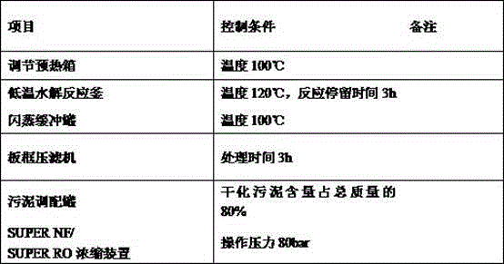
通过以上操作条件控制,得到土壤改良剂70T,液态肥13T。Through the control of the above operating conditions, 70T of soil conditioner and 13T of liquid fertilizer were obtained.
实施案例二 Implementation case two
200TPD市政污泥资源化200TPD municipal sludge recycling
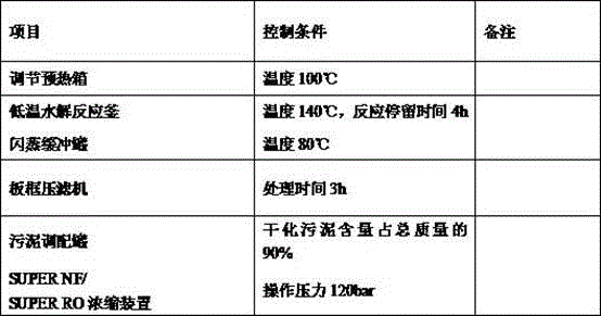
通过以上操作条件控制,得到土壤改良剂65T,液态肥15T。Through the control of the above operating conditions, 65T of soil conditioner and 15T of liquid fertilizer were obtained.
本实用新型提供的污泥资源化处理系统具有的优势如下:The advantages of the sludge resource treatment system provided by the utility model are as follows:
1、污泥全量资源化1. Full resource utilization of sludge
污泥一次性全部生成有机液态肥和土壤改良剂,无需二次处理,用于农业生产和土壤改良,实现全量资源化。The sludge is all produced into organic liquid fertilizer and soil conditioner at one time, without secondary treatment, which is used for agricultural production and soil improvement to realize full resource utilization.
2、实现污泥无害化2. To achieve harmless sludge
有效去除污泥中的微生物和重金属,生成的液态肥、土壤改良剂指标满足国家农业部关于水溶性肥料的相关标准。Effectively remove microorganisms and heavy metals in sludge, and the indicators of liquid fertilizer and soil conditioner produced meet the relevant standards of the Ministry of Agriculture on water-soluble fertilizers.
3、性价比高,发展可持续3. High cost performance and sustainable development
其产品营养成分含量高,品质优,可用于农业、林业的有机肥供给,还可用作土壤改良,产品附加值高,可与现代生态农业相结合,实现环境效益的同时,通过产品的销售收益实现发展可持续。Its products have high nutrient content and high quality, and can be used for the supply of organic fertilizers in agriculture and forestry, as well as for soil improvement. The products have high added value and can be combined with modern ecological agriculture to achieve environmental benefits. At the same time, through product sales Income to achieve sustainable development.
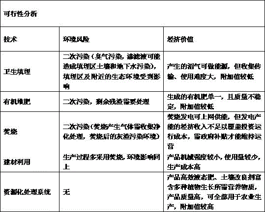
从以上两个表格将本实用新型提供的污泥资源化处理系统与相关技术进行对比分析,明显可以看出,本实用新型提供的污泥资源化处理系统与相关技术具有明显优势,避免了对环境的二次污染,同时,有效提高了对污泥的资源化利用率。From the above two tables, comparing and analyzing the sludge resource treatment system provided by the present utility model and related technologies, it can be clearly seen that the sludge resource treatment system provided by the present utility model and related technologies have obvious advantages, avoiding the need for At the same time, it effectively improves the resource utilization rate of sludge.
最后应说明的是:以上各实施例仅用以说明本实用新型的技术方案,而非对其限制;尽管参照前述各实施例对本实用新型进行了详细的说明,本领域的普通技术人员应当理解:其依然可以对前述各实施例所记载的技术方案进行修改,或者对其中部分或者全部技术特征进行等同替换;而这些修改或者替换,并不使相应技术方案的本质脱离本实用新型各实施例技术方案的范围。Finally, it should be noted that the above embodiments are only used to illustrate the technical solutions of the present utility model, but not to limit them; although the present utility model has been described in detail with reference to the foregoing embodiments, those of ordinary skill in the art should understand that : it can still modify the technical solutions recorded in the foregoing embodiments, or perform equivalent replacements to some or all of the technical features; and these modifications or replacements do not make the essence of the corresponding technical solutions deviate from the various embodiments of the present utility model Scope of technical solutions.
Claims (10)
Priority Applications (1)
| Application Number | Priority Date | Filing Date | Title |
|---|---|---|---|
| CN201921176188.XU CN210340645U (en) | 2019-07-25 | 2019-07-25 | Sludge recycling treatment system |
Applications Claiming Priority (1)
| Application Number | Priority Date | Filing Date | Title |
|---|---|---|---|
| CN201921176188.XU CN210340645U (en) | 2019-07-25 | 2019-07-25 | Sludge recycling treatment system |
Publications (1)
| Publication Number | Publication Date |
|---|---|
| CN210340645U true CN210340645U (en) | 2020-04-17 |
Family
ID=70216250
Family Applications (1)
| Application Number | Title | Priority Date | Filing Date |
|---|---|---|---|
| CN201921176188.XU Active CN210340645U (en) | 2019-07-25 | 2019-07-25 | Sludge recycling treatment system |
Country Status (1)
| Country | Link |
|---|---|
| CN (1) | CN210340645U (en) |
Cited By (1)
| Publication number | Priority date | Publication date | Assignee | Title |
|---|---|---|---|---|
| CN110395860A (en) * | 2019-07-25 | 2019-11-01 | 四川美富特生态科技有限责任公司 | A kind of recycling handles method for dirty mire and system |
-
2019
- 2019-07-25 CN CN201921176188.XU patent/CN210340645U/en active Active
Cited By (2)
| Publication number | Priority date | Publication date | Assignee | Title |
|---|---|---|---|---|
| CN110395860A (en) * | 2019-07-25 | 2019-11-01 | 四川美富特生态科技有限责任公司 | A kind of recycling handles method for dirty mire and system |
| CN110395860B (en) * | 2019-07-25 | 2022-03-08 | 四川美富特环境治理有限责任公司 | A kind of sludge resource treatment method and system |
Similar Documents
| Publication | Publication Date | Title |
|---|---|---|
| CN101746941B (en) | Biological drying method for treating dewatered sludge of urban sewage plant | |
| CN101333123B (en) | Urban Domestic Sludge Recycling Technology | |
| CN101428955B (en) | Mechanical deep dehydration, biological desiccation and reclamation combined treatment process for sewage sludge | |
| CN101618978B (en) | Sludge aerobic mechanical composting method and dynamic roller composting device | |
| CN104177145B (en) | A kind of organic solid castoff pyrohydrolysis high-temperature aerobic composting treatment process | |
| CN103240264B (en) | Have the low emission solid organic castoff treatment system of biogas and Activated Carbon Production concurrently | |
| CN101591130B (en) | Full recycling and zero discharge treatment method of activated sludge | |
| CN105855275A (en) | Method for processing sludge and kitchen wastes | |
| CN102730912B (en) | Integrated sewage-sludge treatment method | |
| CN102992559A (en) | Method for comprehensively utilizing anaerobic digestion and carbonization of municipal sludge | |
| CN102875210A (en) | Method for co-composting of blue-green algae and polluted bottom sediment | |
| CN102030570A (en) | Self-propelled turning device for sludge compost and treatment method | |
| CN102408177A (en) | Biological compound enzyme for sludge recycling and use method thereof | |
| CN103755400A (en) | Method for preparing mineral organic fertilizer by using surplus sludge in municipal sewage plants | |
| CN107500497B (en) | Method and system for treating black and odorous water sludge | |
| CN210419701U (en) | Straw and sludge coprocessing device | |
| CN110395860B (en) | A kind of sludge resource treatment method and system | |
| CN109205971A (en) | A kind of livestock and poultry feces integrated treatment and the device utilized | |
| CN101143758A (en) | Sludge resource treatment complete equipment for urban sewage treatment plant | |
| CN105060669A (en) | Sludge comprehensive utilization method by anaerobic fermentation-carbonization combination technique | |
| CN102874974A (en) | Advanced treatment and comprehensive utilization process for sewage and sludge in sewage treatment plant | |
| CN206783512U (en) | A deep dehydration, drying and carbonization treatment and disposal system for complex conditioning and tempering of sludge | |
| CN210340645U (en) | Sludge recycling treatment system | |
| CN103553288A (en) | Method for preparing water treatment biological activity accelerant from winery wastewater treatment sludge | |
| CN107010806B (en) | Method for treating sludge through hydrothermal carbonization |
Legal Events
| Date | Code | Title | Description |
|---|---|---|---|
| GR01 | Patent grant | ||
| GR01 | Patent grant | ||
| CP03 | Change of name, title or address | ||
| CP03 | Change of name, title or address |
Address after: No. 22 Guanghua Road, Zhunkou Town, Jintang County, Chengdu City, Sichuan Province, 610000 Patentee after: Sichuan Meiyuan Huanneng Technology Co.,Ltd. Address before: 610000 No. 22, Guanghua Road, huaikou Town, Jintang County, Chengdu, Sichuan Patentee before: Sichuan Meifote Eco-technology Co.,Ltd. |
|
| CP03 | Change of name, title or address | ||
| CP03 | Change of name, title or address |
Address after: No. 22 Guanghua Road, Zhunkou Town, Jintang County, Chengdu City, Sichuan Province, 610000 Patentee after: Sichuan Meiyuan Water Cube Technology Co.,Ltd. Country or region after: China Address before: No. 22 Guanghua Road, Zhunkou Town, Jintang County, Chengdu City, Sichuan Province, 610000 Patentee before: Sichuan Meiyuan Huanneng Technology Co.,Ltd. Country or region before: China |