CN210496830U - A device for cathode and anode plate assembly of electrostatic precipitator - Google Patents
A device for cathode and anode plate assembly of electrostatic precipitator Download PDFInfo
- Publication number
- CN210496830U CN210496830U CN201921395563.XU CN201921395563U CN210496830U CN 210496830 U CN210496830 U CN 210496830U CN 201921395563 U CN201921395563 U CN 201921395563U CN 210496830 U CN210496830 U CN 210496830U
- Authority
- CN
- China
- Prior art keywords
- hoisting
- assembly
- anode plate
- cathode
- lifting
- Prior art date
- Legal status (The legal status is an assumption and is not a legal conclusion. Google has not performed a legal analysis and makes no representation as to the accuracy of the status listed.)
- Expired - Fee Related
Links
Images
Landscapes
- Load-Engaging Elements For Cranes (AREA)
Abstract
The utility model belongs to the technical field of the hoist and mount construction of thermal power plant's electrostatic precipitator negative and positive pole and specifically relates to a be used for electrostatic precipitator negative and positive plate sub-assembly device, including an anode plate, a cathode plate, the anode plate with the hoist and mount sub-assembly is constituteed to the cathode plate, still includes one and is used for with outside lifting device matched with hoist and mount complementary unit, hoist and mount complementary unit is used for the chucking anode plate and cathode plate, hoist and mount complementary unit includes that a plurality of chucking setting respectively is in the adjustable fastener at hoist and mount sub-assembly both ends is lieing in each of same end the top of adjustable fastener is equipped with one respectively and plays to rise the piece. The device adopts the way of the assembly to realize the rapid hoisting of the assembly after the combination of the cathode plate and the anode plate, improves the efficiency of the whole hoisting process, can also better improve the protection effect on the assembly in the hoisting process, and has higher operation safety; the construction period is greatly shortened, and the construction cost is reduced.
Description
Technical Field
The utility model belongs to the technical field of the hoist and mount construction of thermal power plant's electrostatic precipitator negative and positive pole and specifically relates to a be used for electrostatic precipitator negative and positive plate sub-assembly device.
Background
The electric dust collector is a high-efficiency energy-saving flue gas purification device, has the advantages of high dust collection efficiency, large flue gas treatment capacity, long service life, low maintenance cost and the like, and is more and more widely applied to electric dust collection under the condition of higher and higher environmental protection requirements at home and abroad at present. The dust-removing principle of electric dust remover is that when the dust-containing smoke gas is passed through high-voltage electric field, it can be collided with positive and negative ions between electrodes or charged in the process of ion diffusion movement, the dust particles with electrons and ions can be moved toward opposite electrode under the action of electric field force and adsorbed on the opposite electrode, and the dust on the electrode can be fallen into dust collector by means of vibration and vibration, etc.
The cathode plate and the anode plate in the electric dust collector belong to main action parts, wherein the anode system comprises an anode suspension device, the anode plate, a striker rod and other parts. The anode plate is a dust collecting electrode and is formed by a thin plate on a special rolling mill. The anode row plane composed of a plurality of anode plates has better rigidity, and the planeness thereof is in a specified range so as to ensure the limit deviation of the distance between the cathode and the anode. The cathode system consists of a cathode hanger, an upper cross beam, a vertical beam, an upper frame, a middle frame, a lower frame, a cathode line and other parts. The cathode wire is a discharge electrode, is made of special equipment, mainly has two types of wire types of a tubular prickle wire series and a spiral wire, and is one of key parts of the electric dust collector. The anode rapping comprises an anode rapping transmission device, a rapping shaft system, a dust bearing and other parts (lateral transmission). The cathode rapping comprises parts (top transmission) such as a cathode rapping transmission device, a vertical shaft, a large pin wheel, a small pin wheel, a rapping shaft system, a dust bearing and the like, or parts (side transmission) such as the cathode rapping transmission device, the rapping shaft system, the dust bearing and the like.
The traditional cathode-anode plate is generally hoisted by single plates due to the influence of the structural strength of the cathode-anode plate, and the combined hoisting mode cannot be used, so that the construction efficiency is not only influenced in the construction process, and the workload of operators is large in the construction process.
SUMMERY OF THE UTILITY MODEL
The utility model discloses a solve the technical scheme that one of above-mentioned technical problem adopted and be: the utility model provides a be used for electrostatic precipitator negative and positive plate sub-assembly device, including an anode plate, one with the cathode plate of anode plate laminating, anode plate with the hoist and mount sub-assembly is constituteed to the cathode plate, still includes one be used for with outside lifting device matched with hoist and mount complementary unit, hoist and mount complementary unit is used for the chucking anode plate and cathode plate, hoist and mount complementary unit includes that a plurality of chucking respectively sets up the adjustable fastener at hoist and mount sub-assembly both ends is lieing in each with the one end the top of adjustable fastener is equipped with a piece that rises respectively, each adjustable fastener links to each other rather than the piece that rises that corresponds position department through wire rope respectively, each the top that rises the piece that rises is used for respectively and lifts by crane equipment and links to each.
Preferably, the adjustable clamping member includes a U-shaped clamping seat horizontally arranged, a U-shaped cavity of the U-shaped clamping seat is used for clamping the end portion of the hoisting assembly, adjusting bolts with inner ends extending into the U-shaped cavity are respectively screwed in threaded holes of horizontal sections of upper and lower portions of the U-shaped clamping seat, a fixed suction cup is respectively and fixedly mounted on an inner end surface of each adjusting bolt, an adjusting crank is respectively and fixedly mounted on an outer end surface of each adjusting bolt, a fixed lug seat is respectively welded on an outer end surface of each U-shaped clamping seat, and the fixed lug seat is used for being matched with a hook of a lower end portion of a steel wire rope at a position corresponding to the fixed lug seat.
Preferably, the lifting member comprises a lifting beam, a plurality of lower lug seats are fixedly welded at intervals at the bottom of the lifting beam along the length direction of the lifting beam respectively, the lower lug seats are used for being matched with hooks at the upper end parts of the steel wire ropes at the corresponding positions, a plurality of lifting bolts are screwed at intervals at the top of the lifting beam along the length direction of the lifting beam respectively, and lug holes matched with hooks of external lifting equipment are arranged at the tops of the lifting bolts respectively.
Preferably, the lifting cross beam is an i-shaped steel beam with an i-shaped section.
The beneficial effects of the utility model are embodied in: the device adopts the way of the assembly to realize the rapid hoisting of the assembly after the combination of the cathode plate and the anode plate, improves the efficiency of the whole hoisting process, can also better improve the protection effect on the assembly in the hoisting process, and has higher operation safety; the construction period is greatly shortened, and the construction cost is reduced.
Drawings
In order to more clearly illustrate the embodiments of the present invention or the technical solutions in the prior art, the drawings used in the embodiments or the technical solutions in the prior art will be briefly described below. Throughout the drawings, like elements or components are generally identified by like reference numerals. In the drawings, elements or components are not necessarily drawn to scale.
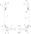
Fig. 1 is a schematic view of the partial cross-sectional structure of the present invention.
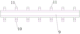
Fig. 2 is a schematic view of an a-direction structure of the lifting beam in fig. 1 according to the present invention.
In the figure, 1, a hoisting assembly; 101. an anode plate member; 102. a cathode plate; 2. A wire rope; 3. a U-shaped card seat; 4. Adjusting the bolt; 5. Fixing the sucker; 6. adjusting a crank; 7. fixing the ear seat; 8. hooking; 9. hoisting the cross beam; 10. a lower ear seat; 11. hoisting the bolt; 12. an ear hole.
Detailed Description
Embodiments of the present invention will be described in detail below with reference to the accompanying drawings. The following examples are only for illustrating the technical solutions of the present invention more clearly, and therefore are only examples, and the protection scope of the present invention is not limited thereby.
As shown in fig. 1-2, a cathode plate assembly device for an electric dust collector comprises an anode plate 101, a cathode plate 102 attached to the anode plate 101, wherein the anode plate 101 and the cathode plate 102 form a hoisting assembly 1, and the device further comprises a hoisting auxiliary mechanism matched with external hoisting equipment, the hoisting auxiliary mechanism is used for clamping the anode plate 101 and the cathode plate 102, the hoisting auxiliary mechanism comprises a plurality of adjustable clamping pieces which are respectively clamped at two ends of the hoisting assembly 1, a hoisting piece is respectively arranged above each adjustable clamping piece at the same end, each adjustable clamping piece is respectively connected with the hoisting piece at the corresponding position through a steel wire rope 2, and the top of each hoisting piece is respectively used for being connected with hoisting equipment.
The anode plate 101 and the cathode plate 102 can be combined and hoisted through the device, and compared with a traditional single-piece hoisting mode, the hoisting efficiency is higher. Before hoisting, the number of the adjustable clamping pieces is selected according to the size and the width of a hoisting assembly 1 to be hoisted, the adjusting bolts 4 are controlled by adjusting the adjusting cranks 6, so that the upper part and the lower part of the hoisting assembly 1 are tightly supported by the two oppositely arranged fixed suckers 5, and then each adjustable clamping piece is clamped with a hoisting piece above the adjustable clamping piece in a matching way through a steel wire rope 2 with hooks 8 at two ends.
Preferably, the adjustable clamping member includes a horizontally disposed U-shaped clamping seat 3, a U-shaped cavity of the U-shaped clamping seat 3 is used for clamping the end portion of the hoisting assembly 1, adjusting bolts 4 with inner ends extending into the U-shaped cavity are respectively screwed in threaded holes of horizontal sections of upper and lower portions of the U-shaped clamping seat 3, a fixed suction cup 5 is respectively and fixedly mounted on inner end faces of the adjusting bolts 4, an adjusting crank 6 is respectively and fixedly mounted on outer end faces of the adjusting bolts 4, a fixed lug seat 7 is respectively welded on outer end faces of the U-shaped clamping seats 3, and the fixed lug seat 7 is used for being matched with a hook 8 of a lower end portion of the steel wire rope 2 at a position corresponding to the fixed lug seat 7.
The adjusting bolts 4 and the fixed suckers 5 on the adjusting bolts can be conveniently adjusted by arranging the adjusting cranks 6, the two oppositely arranged fixed suckers 5 can clamp the hoisting assembly 1, and the stability during hoisting is ensured.
Preferably, the hoisting part comprises a hoisting beam 9, a plurality of lower lug seats 10 are respectively fixedly welded at intervals at the bottom of the hoisting beam 9 along the length direction of the hoisting beam, the lower lug seats 10 are used for being matched with hooks 8 at the upper end parts of the steel wire ropes 2 at the corresponding positions, a plurality of hoisting bolts 11 are respectively screwed at intervals at the top of the hoisting beam 9 along the length direction of the hoisting beam, and lug holes 12 used for being matched with the hooks 8 of external hoisting equipment are respectively arranged at the top of each hoisting bolt 11.
The hoisting bolts 11 are mainly arranged to selectively install different numbers of hoisting bolts 11 or disassemble a part of hoisting bolts 11 according to requirements, and meanwhile, the hoisting bolts 11 can be screwed and adjusted within a certain small distance range, so that the screwing height parts of the hoisting bolts 11 are completely the same, the stress of multiple points and multiple angles during hoisting is ensured, and the comprehensiveness of the hoisting force is ensured; of course, the height and the rod of each lifting bolt 11 can be the same, and no requirement is made specifically.
The lifting cross beam 9 provided with the I-shaped steel beam can effectively connect the lifting assembly with the lifting assembly through the adjustable clamping pieces with required number, so that the connection of multiple lifting points during subsequent lifting is ensured, and the stability is stronger.
Preferably, the hoisting cross beam 9 is an i-shaped steel beam with an i-shaped section.
Before hoisting, the number of the adjustable clamping pieces is selected according to the size and the width of a hoisting assembly 1 to be hoisted, the adjusting bolts 4 are controlled by adjusting the adjusting cranks 6, so that the upper part and the lower part of the hoisting assembly 1 are tightly propped against by the two oppositely arranged fixed suckers 5, and then each adjustable clamping piece is respectively matched and clamped with a hoisting piece above the adjustable clamping piece through a steel wire rope 2 with hooks 8 at two ends; then, the lifting steel bar hooks on the lifting equipment are matched with the lug holes 12 on the lifting bolts 11 on the I-shaped steel beam at the corresponding position of the employer, and the lifting equipment is started to realize upward lifting.
The above embodiments are only used to illustrate the technical solution of the present invention, and not to limit the same; although the present invention has been described in detail with reference to the foregoing embodiments, it should be understood by those skilled in the art that: the technical solutions described in the foregoing embodiments may still be modified, or some or all of the technical features may be equivalently replaced; such modifications and substitutions do not substantially depart from the scope of the embodiments of the present invention, and are intended to be covered by the claims and the specification; to those skilled in the art, any alternative improvements or changes made to the embodiments of the present invention are all within the scope of the present invention.
The parts of the present invention not described in detail are the known techniques of those skilled in the art.
Claims (4)
Priority Applications (1)
| Application Number | Priority Date | Filing Date | Title |
|---|---|---|---|
| CN201921395563.XU CN210496830U (en) | 2019-08-27 | 2019-08-27 | A device for cathode and anode plate assembly of electrostatic precipitator |
Applications Claiming Priority (1)
| Application Number | Priority Date | Filing Date | Title |
|---|---|---|---|
| CN201921395563.XU CN210496830U (en) | 2019-08-27 | 2019-08-27 | A device for cathode and anode plate assembly of electrostatic precipitator |
Publications (1)
| Publication Number | Publication Date |
|---|---|
| CN210496830U true CN210496830U (en) | 2020-05-12 |
Family
ID=70544111
Family Applications (1)
| Application Number | Title | Priority Date | Filing Date |
|---|---|---|---|
| CN201921395563.XU Expired - Fee Related CN210496830U (en) | 2019-08-27 | 2019-08-27 | A device for cathode and anode plate assembly of electrostatic precipitator |
Country Status (1)
| Country | Link |
|---|---|
| CN (1) | CN210496830U (en) |
-
2019
- 2019-08-27 CN CN201921395563.XU patent/CN210496830U/en not_active Expired - Fee Related
Similar Documents
| Publication | Publication Date | Title |
|---|---|---|
| CN210496830U (en) | A device for cathode and anode plate assembly of electrostatic precipitator | |
| CN203044170U (en) | Large cathode frame of electric dust removal device | |
| CN218944191U (en) | H-shaped steel safety flat net suspension device | |
| CN201272657Y (en) | Special apparatus for anode framework assembly and swinging of revolving furnace flue gas cleaning equipment | |
| CN218058086U (en) | A hoist device for prefabricating air conditioner plate | |
| CN201703960U (en) | Hoisting clamp of electric dust removal and collecting pole plate | |
| CN217431946U (en) | Adopt horizontal electrostatic precipitator of CW type anode plate | |
| CN213976650U (en) | A New Type Fixture Crane Claw Nail | |
| CN202283490U (en) | Electric dust collector and anodal collecting plate | |
| CN222594073U (en) | Auxiliary rod taking tool | |
| CN209680323U (en) | A kind of wet electrical dust precipitator anode plate hanging mechanism | |
| CN102311042A (en) | Lifting appliance of transport system for intensive overhaul of electrolytic bath and lifting method | |
| CN205518230U (en) | Vertical tubular electrostatic precipitator of cathode system lower part area stay structure | |
| CN222518841U (en) | Active connection structure for electric dust remover | |
| CN208965050U (en) | A kind of simple demagnetization drainage device | |
| CN212712336U (en) | Lithium ion battery group hoist device | |
| CN109440138A (en) | Embrace the laterally-clamped anode clamp of formula | |
| CN219797925U (en) | Fire-blocking structure of heating furnace | |
| CN204380862U (en) | Tube-type esp | |
| CN217341826U (en) | Novel wet electric weight block | |
| CN221066154U (en) | Simple and easy horizontal continuous casting crystallizer copper sheathing remove device | |
| CN223547563U (en) | Tool for lifting turbine bearing upper cover body | |
| CN221610747U (en) | An assembled bracket integral lifting pulley assembly device | |
| CN206842851U (en) | A kind of wet cottrell positive plate assembling lifting pallet | |
| CN219009682U (en) | Multifunctional hanging bracket for engineering construction |
Legal Events
| Date | Code | Title | Description |
|---|---|---|---|
| GR01 | Patent grant | ||
| GR01 | Patent grant | ||
| CF01 | Termination of patent right due to non-payment of annual fee | ||
| CF01 | Termination of patent right due to non-payment of annual fee |
Granted publication date: 20200512 |