CN210664355U - Mechanism for acquiring casing diameter by visual identification - Google Patents
Mechanism for acquiring casing diameter by visual identification Download PDFInfo
- Publication number
- CN210664355U CN210664355U CN201921054183.XU CN201921054183U CN210664355U CN 210664355 U CN210664355 U CN 210664355U CN 201921054183 U CN201921054183 U CN 201921054183U CN 210664355 U CN210664355 U CN 210664355U
- Authority
- CN
- China
- Prior art keywords
- casing
- diameter
- obtaining
- inflated
- industrial camera
- Prior art date
- Legal status (The legal status is an assumption and is not a legal conclusion. Google has not performed a legal analysis and makes no representation as to the accuracy of the status listed.)
- Active
Links
- 230000007246 mechanism Effects 0.000 title claims abstract description 39
- 230000000007 visual effect Effects 0.000 title claims abstract description 39
- 235000013580 sausages Nutrition 0.000 claims description 43
- 238000004519 manufacturing process Methods 0.000 claims description 27
- 238000004804 winding Methods 0.000 claims description 23
- 238000001125 extrusion Methods 0.000 claims description 18
- 238000012545 processing Methods 0.000 claims description 6
- 230000008859 change Effects 0.000 claims description 5
- 230000001360 synchronised effect Effects 0.000 claims description 5
- 238000005507 spraying Methods 0.000 claims description 4
- 238000005096 rolling process Methods 0.000 claims description 2
- 238000004513 sizing Methods 0.000 claims description 2
- 238000005259 measurement Methods 0.000 abstract description 13
- 238000000034 method Methods 0.000 abstract description 10
- 230000008569 process Effects 0.000 abstract description 8
- 238000001514 detection method Methods 0.000 description 8
- 239000000463 material Substances 0.000 description 4
- 238000010586 diagram Methods 0.000 description 3
- 238000009776 industrial production Methods 0.000 description 2
- 238000000691 measurement method Methods 0.000 description 2
- 238000012986 modification Methods 0.000 description 2
- 230000004048 modification Effects 0.000 description 2
- 230000003287 optical effect Effects 0.000 description 2
- 241000282461 Canis lupus Species 0.000 description 1
- 102000008186 Collagen Human genes 0.000 description 1
- 108010035532 Collagen Proteins 0.000 description 1
- 229920002678 cellulose Polymers 0.000 description 1
- 239000001913 cellulose Substances 0.000 description 1
- 229920001436 collagen Polymers 0.000 description 1
- 238000004891 communication Methods 0.000 description 1
- 238000006073 displacement reaction Methods 0.000 description 1
- 230000007613 environmental effect Effects 0.000 description 1
- 238000007667 floating Methods 0.000 description 1
- 238000011897 real-time detection Methods 0.000 description 1
Images


Landscapes
- Length Measuring Devices By Optical Means (AREA)
Abstract
The utility model provides a mechanism for acquiring the diameter of a casing by visual identification, which takes a picture of an aerated casing passing through at high speed in real time by an industrial camera provided with a large depth-of-field lens at high frequency, and processes the taken image by a control processor to obtain the diameter size of the casing; because the diameter of the casing is detected in an inflated state, the accuracy of the measurement of the diameter of the casing can be ensured; the large-depth-of-field lens is adopted for shooting, the sizes of objects which are shot by the large-depth-of-field lens and have long and short distances are consistent, the shooting time is not limited, and real-time shooting can be realized; and the depth of field lens can measure the diameters of casings with different sizes, has wide application range and meets the use requirement.
Description
Technical Field
The utility model relates to a casing diameter measuring equipment especially relates to a mechanism for utilize visual identification to acquire casing diameter.
Background
The artificial casings (such as plastic casings, cellulose casings and collagen casings) need to be detected in the production process, and the diameter of the formed casings is ensured by adjusting production equipment according to the detected conditions. Or the casings with the diameter size outside the floating range are removed, so that the production quality of the casings is ensured. In order to save cost, the sausage casing diameter detection can be carried out manually by some sausage casing production enterprises, the diameter of the sausage casing is measured by manually holding a ruler, but the manual detection is time-consuming and labor-consuming, the efficiency is low, the precision difference of the manual detection is large, and the detection requirement cannot be met; the manual detection can not achieve full real-time detection, unqualified products with the diameters in the intermittent time of the manual detection cannot be found, and even if the size change of the formed casing is detected manually, the diameter of the casing is corrected in time and accurately when the casing production equipment is adjusted manually.
Some casing manufacturing enterprises can use the laser diameter gauge to detect the casing diameter, and the laser diameter gauge that has now generally adopts laser scanning calibrator: the laser scanning diameter measuring instrument system adopts the light beam emitted by a laser to form a continuous high-speed scanning light beam parallel to an optical axis after passing through a polyhedral scanning rotating mirror and a scanning optical system, the workpiece arranged in a measuring area is scanned at a high speed and is received by a photoelectric receiver arranged opposite to the workpiece, and the light projected on the photoelectric receiver is intercepted when the light beam scans the workpiece, so that the data related to the diameter of the workpiece can be obtained by analyzing the signal output by the photoelectric receiver. However, in order to ensure high precision and reliability of measurement, the laser scanning caliper must meet the following three basic requirements: (1) the laser beam should vertically irradiate the surface of the measured object; (2) the light beam must do uniform linear scanning motion to the surface of the object; (3) the scan time must be measured accurately. In reality, the scanning speed is not constant but changes along with the change of the angular displacement of the scanning rotating mirror, so that principle errors are generated and the detection requirements cannot be met; and the laser equipment has higher price and is sensitive to the environmental requirement.
Accordingly, the prior art is yet to be improved and developed.
Disclosure of Invention
An object of the utility model is to provide an utilize vision identification to acquire mechanism of casing diameter aims at solving one or more technical problem that current laser diameter gauge exists.
The technical scheme of the utility model as follows: a mechanism for obtaining the diameter of casing by visual recognition, comprising:
the industrial camera is provided with a depth-of-field lens and is used for shooting the sausage casing irradiated by light;
and the control processor is used for processing the image shot by the industrial camera to obtain the diameter size of the sausage casing.
The mechanism for acquiring the diameter of the casing by using visual recognition is characterized in that the casing to be detected comprises, but is not limited to, a flat casing, a casing in an inflated state, a casing in a suspended state, and a casing in an inflated and suspended state.
The mechanism for acquiring the diameter of the casing by utilizing visual recognition is characterized in that an industrial camera shoots the casing irradiated by light, wherein the light irradiation is provided for the casing by a light source built in the industrial camera.
The mechanism for acquiring the diameter of the sausage casing by utilizing visual recognition is characterized in that an industrial camera shoots the sausage casing irradiated by light, wherein the light irradiation is provided for the sausage casing by an independently arranged light source.
The mechanism for acquiring the diameter of the casing by using visual identification comprises but is not limited to measuring the diameter of the casing produced by casing production equipment; measuring the diameter of the casing before shrinkage; measuring the diameter of the casing in a separate apparatus for casing sizing; the change in the diameter dimension of the casing after humidification or oil spraying was measured.
The mechanism for acquiring the diameter of the casing by utilizing visual recognition is characterized in that the diameter of the casing produced by the casing production equipment is measured, the casing is extruded from an extrusion head of the casing production equipment and is wound on a casing tube by the driving of a winding device, the casing positioned between the extrusion head and the winding device is inflated to form a cylinder shape, and the diameter of the suspended inflated casing positioned between the extrusion head and the winding device is measured by the mechanism for acquiring the diameter of the casing by utilizing visual recognition.
The mechanism for acquiring the diameter of the casing by using visual identification is characterized in that a synchronous adjusting device is arranged on the casing production equipment, receives a casing diameter size deviation signal sent by the mechanism for acquiring the diameter of the casing by using visual identification, and timely adjusts the production diameter of the casing according to the casing diameter size deviation signal.
The mechanism for acquiring the diameter of the sausage casing by utilizing visual recognition is characterized in that an inflation pipeline is arranged at the extrusion head to inflate the sausage casing between the extrusion head and the winding device.
The mechanism for acquiring the diameter of the casing by utilizing visual identification is characterized in that the diameter of the casing before shrinkage is measured, the casing is unreeled from a casing drum to casing shrinkage equipment under the driving of an unreeling device, the casing between the unreeling device and the casing shrinkage equipment is inflated to form a cylinder shape, and the diameter of the suspended inflated casing between the unreeling device and the casing shrinkage equipment is measured by the mechanism for acquiring the diameter of the casing by utilizing visual identification.
The mechanism for acquiring the diameter of the sausage casing by using visual recognition is characterized in that an inflation pipeline is arranged on a sleeve shrinkage rod of the sausage casing sleeve shrinkage device, and the sausage casing positioned between the unwinding device and the sausage casing sleeve shrinkage device is inflated.
The utility model has the advantages that: the utility model provides a mechanism for acquiring the diameter of the casing by visual identification, which takes a picture of the high-speed passing aerated casing in real time by an industrial camera provided with a large depth-of-field lens at high frequency, and processes the taken image by a control processor to obtain the diameter size of the casing; because the diameter of the casing is detected in an inflated state, the accuracy of the measurement of the diameter of the casing can be ensured; the large-depth-of-field lens is adopted for shooting, the sizes of objects which are shot by the large-depth-of-field lens and have long and short distances are consistent, the shooting time is not limited, and real-time shooting can be realized; and the depth of field lens can measure the diameters of casings with different sizes, has wide application range and meets the use requirement.
Drawings
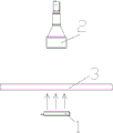
Fig. 1 is a schematic structural diagram of a mechanism for acquiring the diameter of the sausage casing by visual recognition in the present invention.
Fig. 2 is a schematic diagram of the sausage casing produced by the sausage casing production equipment by the mechanism for acquiring the diameter of the sausage casing by visual recognition in the utility model.
Fig. 3 is a schematic diagram of the mechanism for acquiring the diameter of the sausage casing by visual recognition in the utility model, which is used for measuring the diameter of the sausage casing before shrinkage.
Detailed Description
Reference will now be made in detail to embodiments of the present invention, examples of which are illustrated in the accompanying drawings, wherein like reference numerals refer to the same or similar elements or elements having the same or similar function throughout. The embodiments described below with reference to the accompanying drawings are exemplary only for the purpose of explaining the present invention, and should not be construed as limiting the present invention.
In the description of the present invention, it is to be understood that the terms "center", "longitudinal", "lateral", "length", "width", "thickness", "upper", "lower", "front", "rear", "left", "right", "vertical", "horizontal", "top", "bottom", "inner", "outer", "clockwise", "counterclockwise", and the like indicate orientations or positional relationships based on the orientations or positional relationships shown in the drawings, and are only for convenience of description and to simplify the description, but do not indicate or imply that the device or element referred to must have a particular orientation, be constructed and operated in a particular orientation, and therefore should not be construed as limiting the present invention. Furthermore, the terms "first", "second" and "first" are used for descriptive purposes only and are not to be construed as indicating or implying relative importance or implicitly indicating the number of technical features indicated. Thus, features defined as "first", "second", may explicitly or implicitly include one or more of the described features. In the description of the present invention, "a plurality" means two or more unless specifically limited otherwise.
In the description of the present invention, it is to be noted that, unless otherwise explicitly specified or limited, the terms "mounted," "connected," and "connected" are to be construed broadly, and may be, for example, fixedly connected, detachably connected, or integrally connected; may be mechanically connected, may be electrically connected or may be in communication with each other; either directly or indirectly through intervening media, either internally or in any other relationship. The specific meaning of the above terms in the present invention can be understood according to specific situations by those skilled in the art.
In the present disclosure, unless expressly stated or limited otherwise, the first feature "on" or "under" the second feature may comprise direct contact between the first and second features, or may comprise contact between the first and second features not directly. Also, the first feature being "on," "above" and "over" the second feature includes the first feature being directly on and obliquely above the second feature, or merely indicating that the first feature is at a higher level than the second feature. A first feature being "under," "below," and "beneath" a second feature includes the first feature being directly under and obliquely below the second feature, or simply meaning that the first feature is at a lesser elevation than the second feature.
The following disclosure provides many different embodiments or examples for implementing different features of the invention. In order to simplify the disclosure of the present invention, the components and arrangements of specific examples are described below. Of course, they are merely examples and are not intended to limit the present invention. Furthermore, the present invention may repeat reference numerals and/or reference letters in the various examples, which have been repeated for purposes of simplicity and clarity and do not in themselves dictate a relationship between the various embodiments and/or arrangements discussed. In addition, the present disclosure provides examples of various specific processes and materials, but one of ordinary skill in the art may recognize applications of other processes and/or use of other materials.
As shown in fig. 1, a mechanism for obtaining a diameter of a casing by visual recognition includes:
an industrial camera 2 provided with a depth-of-field lens, which shoots a sausage casing 3 irradiated by light;
the control processor (not shown) processes the image captured by the industrial camera 2 to obtain the diameter size of the casing 3.
In the prior art, an array CCD industrial camera and an upper computer are used for measuring the diameter of the sausage casing, the array CCD is used for non-contact measurement, the array CCD is placed in a light path, a measured object is placed in the light path in front of the CCD, and light emitted to the CCD is partially blocked by an object, so that a signal output by the CCD has a notch, obviously, the width of the notch and the size of the object have a one-to-one correspondence relationship, and the upper computer processes the notch to obtain the number of CCD pixels corresponding to the notch, thereby calculating the diameter (width) of the measured sausage casing. However, such a caliper has the following problems: (1) in the measuring method, the cost of the CCD is expensive, and the application of the sausage casing diameter measuring equipment is limited to a certain extent; moreover, the CCD light sensitive area has certain size limitation, which directly limits the size of the measured sausage casing, thereby limiting the measurement of the diameter of the sausage casing. (2) In this measurement method, only the diameter of the flat casing is measured, and the flat casing needs to be closely attached to the flat plate during measurement, but the measurement method has a large error in the measurement of the diameter of the casing in the suspended state and the inflated state, and is not suitable for measuring the diameter of the casing in the suspended state and the inflated state. (3) When measuring the diameter of a flat casing, if there is residual air inside the flat casing, the measurement may also be inaccurate.
The industrial camera 2 photographs the casing 3 irradiated with light, and the casing can be irradiated with light by a light source built in the industrial camera or by a light source 1 provided separately. The light source provides light irradiation for the casing, so that the view of the industrial camera 2 provided with the depth-of-field lens is clearer, the influence of the light darkness of the ambient light is avoided, and the definition of a shot image is ensured.
In the technical scheme, the industrial camera 2 provided with the depth-of-field lens is adopted, so that the diameters of casings 3 to be measured in different states, such as flat casings, casings in an inflated state or casings in a suspended state, and the like, can be measured, and the diameters of casings 3 to be measured in different sizes (the size of the casings 3 to be measured is limited by the view finding width of the depth-of-field lens) can be measured, so that the application range is wide, and the measurement precision is high.
As a preferable scheme, the depth of field lens in the industrial camera 2 is a large depth of field lens, and the industrial camera 2 provided with the large depth of field lens is used for taking a high-frequency picture of the aerated casing passing through at high speed in real time, wherein the large depth of field lens is a telecentric lens with the depth of field of 25mm or more.
In the technical scheme, the industrial camera 2 provided with the depth-of-field lens shoots the casing 3, and the depth-of-field lens collects parallel images of the casing 3; the size of the image shot by the lens with the large depth of field is the same no matter the distance of the shot target is far and near, so the technical scheme has no limitation on the shooting time and can realize real-time shooting.
Specifically, by adopting the industrial camera 2 equipped with a lens with a large depth of field, the diameter of the casing 3 conveyed at the fastest conveying speed in the current industrial production can be measured. In the technical scheme, in order to improve the measurement efficiency, the casing 3 passing at a high speed is shot at a high frequency, the passing speed of the casing 3 depends on the highest shooting frequency (namely, frame rate) of the industrial camera 2, and the higher the shooting frequency of the industrial camera 2 is, the higher the allowable casing passing speed is.
At present, the high-frequency industrial camera 2 captures a motion track of a high-speed moving object at a high-frequency shooting speed, can capture pictures which cannot be captured by naked eyes, and is an important tool for an industrial production line. The basic parameters of the high-frequency industrial camera 2 are related to the model of the machine, the signals are different, and the basic parameters are also different, such as the imported i-speed 3 of olympus, the resolution of which is 1280 x 1024 at 2000 frames/second, and the maximum frame rate is 150000 frames/second; and for example, the home-made Qianyou wolf 2F-16 with the highest resolution of 16M (4600 multiplied by 3440) supports the shooting speed of 65000 frames/second in small picture. By adopting the industrial camera 2 with a proper frame rate, the passing speed of the casing 3 can be effectively improved, and the detection efficiency of the diameter of the casing 3 is improved.
The frame rate of the cameras is related to pixels, and generally, the higher the resolution is, the lower the frame rate is, and the frame rates of industrial cameras of different brands are slightly different; the required resolution of the industrial camera can be calculated according to the size of the casing 3, the resolution to be achieved and the performance of the used software, and different industrial cameras are selected according to the temperature, humidity, interference condition and lighting condition which need to be considered in the field environment. Therefore, the industrial camera 2 with an appropriate frame rate may be selected according to actual shooting requirements.
In the technical scheme, the processing process of the image by the control processor is basically the same as the processing process of the image by the diameter measuring instrument for measuring the diameter of the casing by using the CCD industrial camera in the prior art, and the technical scheme does not improve the processing of the image by the control processor.
The mechanism for acquiring the diameter of the casing by utilizing visual identification can be applied to various occasions needing measuring the diameter of the casing, and has wide application range. For example, diameter measurements can be made on the casing 3 during the casing production process; the diameter of the sausage casing 3 can also be measured after production and before shrinkage; the method can be applied to single equipment for measuring the size of the casing; the device can also be applied to equipment for humidifying or spraying oil on the inner part and the outer part of the sausage casing, and the diameter change of the sausage casing after the humidifying or spraying oil is detected; and so on.
As shown in fig. 2, in order to measure the diameter of the casing 3 in the casing production process, the casing 3 is extruded from an extrusion head 41 of the casing production equipment and is wound on a casing drum 44 by the driving of a winding device, the casing 3 between the extrusion head 41 and the winding device is inflated to form a cylinder shape, and the suspended inflated casing 3 between the extrusion head 41 and the winding device is measured by a mechanism for acquiring the diameter of the casing by visual recognition.
Further, an inflation duct may be provided at the extrusion head 41 to inflate the casing 3 extruded from the extrusion head 41.
Further, the winding device comprises a first winding wheel 42 and a second winding wheel 43, and after the casing 3 is extruded from the extrusion head 41, the casing is pressed into a flat shape through a gap between the first winding wheel 42 and the second winding wheel 43 under the driving of the first winding wheel 42 and the second winding wheel 43 and is wound on the casing drum 44.
According to actual needs, the rotating speed of the first winding wheel 42 and the second winding wheel 43 is controlled, so that the conveying speed of the sausage casing 3 is changed. In this embodiment, the rotating speeds of the first winding wheel 42 and the second winding wheel 43 are controlled to enable the sausage casing 3 between the extrusion head 41 and the winding device to pass through quickly, so that the measuring speed of the diameter of the sausage casing 3 is increased, and the sausage casing production equipment can be adjusted in real time according to the measured diameter of the sausage casing 3 to ensure that the produced sausage casing 3 meets the requirements.
According to the mechanism for acquiring the diameter of the casing by visual recognition, the diameter size of the casing 3 is detected, a synchronous adjusting device can be installed on the casing production equipment, the synchronous adjusting device receives a casing diameter size deviation signal sent by the mechanism for acquiring the diameter of the casing by visual recognition, the production diameter of the casing is adjusted in time according to the casing diameter size deviation signal, and the error of the casing diameter during production can be reduced.
As shown in fig. 3, in order to measure the diameter of the casing 3 after production and before casing shrinkage, the casing 3 is unwound from the casing drum 54 to the casing shrinkage device 51 under the driving of the unwinding device, the casing 3 between the unwinding device and the casing shrinkage device 51 is inflated to form a cylinder, and the suspended inflated casing 3 between the unwinding device and the casing shrinkage device 51 is measured by the mechanism for obtaining the diameter of the casing through visual recognition.
Further, an inflation pipeline may be provided on the shrinking rod of the casing shrinking device 51 to inflate the casings 3 conveyed by the unwinding device.
Further, the unwinding device comprises a first unwinding wheel 52 and a second unwinding wheel 53, and the flat casing 3 is unwound from the casing drum 54 to the casing shrinking device 51 under the driving of the first unwinding wheel 52 and the second unwinding wheel 53.
The feeding speed of the casing 3 is changed by controlling the rotation speed of the first unwinding wheel 52 and the second unwinding wheel 53 according to actual needs. In this embodiment, the sausage casing 3 between the unwinding device and the sausage casing shrinking device 51 is made to pass through quickly by controlling the rotating speeds of the first unwinding wheel 52 and the second unwinding wheel 53, so as to accelerate the measurement of the diameter of the sausage casing 3, and the sausage casing 3 which does not conform to the size can be removed according to the real-time measured diameter of the sausage casing 3, thereby ensuring the production quality of the shrunk sausage casing.
In the technical scheme, the industrial camera provided with the large-depth-of-field lens is used for shooting the aerated casing 3 passing through at a high speed in real time at a high frequency, and the control processor is used for processing the shot image to obtain the diameter size of the casing 3; because the diameter of the casing is detected in an inflated state, the accuracy of the measurement of the diameter of the casing can be ensured; the large-depth-of-field lens is adopted for shooting, the sizes of objects which are shot by the large-depth-of-field lens and have long and short distances are consistent, the shooting time is not limited, and real-time shooting can be realized; and the depth of field lens can measure the diameters of casings with different sizes, has wide application range and meets the use requirement.
In the description herein, references to the description of the terms "one embodiment," "certain embodiments," "an illustrative embodiment," "an example," "a specific example," or "some examples," etc., mean that a particular feature, structure, material, or characteristic described in connection with the embodiment or example is included in at least one embodiment or example of the invention. In this specification, schematic representations of the above terms do not necessarily refer to the same embodiment or example. Furthermore, the particular features, structures, materials, or characteristics described may be combined in any suitable manner in any one or more embodiments or examples.
It is to be understood that the invention is not limited to the above-described embodiments, and that modifications and variations may be made by those skilled in the art in light of the above teachings, and all such modifications and variations are intended to be included within the scope of the invention as defined in the appended claims.
Reference numerals
1, a light source; 2, a camera; 3, casing; 41 an extrusion head; 42 a first winding wheel; 43, second rolling; 44/54 enteric-coated tube; 51 casing shrink equipment; 52 a first unwind wheel; 53 second unwinding wheel.
Claims (10)
1. A mechanism for obtaining a casing diameter using visual recognition, comprising:
the industrial camera is provided with a depth-of-field lens and is used for shooting the sausage casing irradiated by light;
and the control processor is used for processing the image shot by the industrial camera to obtain the diameter size of the sausage casing.
2. The mechanism for obtaining the diameter of casing with visual identification as claimed in claim 1, wherein the casing to be measured includes but is not limited to flat casing, casing in inflated state, casing in suspended state, casing in inflated and suspended state.
3. The mechanism for obtaining the diameter of the casing by visual identification as claimed in claim 1, wherein the casing is shot by an industrial camera, wherein the casing is irradiated by light provided by a light source built in the industrial camera.
4. The mechanism for obtaining the diameter of the casing by visual identification as claimed in claim 1, wherein the industrial camera photographs the casing illuminated by light, wherein the light is provided to the casing by a light source provided separately.
5. The mechanism for obtaining the diameter of the casing by visual identification as claimed in claim 1, wherein the mechanism includes but is not limited to measuring the diameter of the casing produced by the casing production equipment; measuring the diameter of the casing before shrinkage; measuring the diameter of the casing in a separate apparatus for casing sizing; the change in the diameter dimension of the casing after humidification or oil spraying was measured.
6. The mechanism for obtaining the diameter of the casing through visual recognition is characterized in that the diameter of the casing produced by the casing production equipment is measured, the casing is extruded from an extrusion head of the casing production equipment and is wound on a casing drum through the driving of a winding device, the casing between the extrusion head and the winding device is inflated to form a cylindrical shape, and the mechanism for obtaining the diameter of the casing through visual recognition measures the diameter of the suspended inflated casing between the extrusion head and the winding device.
7. The mechanism for obtaining the diameter of the casing by visual recognition as claimed in claim 6, wherein a synchronous adjusting device is installed on the casing production equipment, the synchronous adjusting device receives the casing diameter size deviation signal sent by the mechanism for obtaining the diameter of the casing by visual recognition, and the casing production diameter is adjusted in time according to the casing diameter size deviation signal.
8. The mechanism for obtaining the diameter of the casing through visual identification as claimed in claim 6, wherein an inflation pipe is arranged at the extrusion head, and the casing between the extrusion head and the rolling device is inflated.
9. The apparatus of claim 5, wherein the apparatus for measuring the diameter of the casing is driven by an unwinding device to unwind the casing from the casing drum to the casing shrinking device, and the casing between the unwinding device and the casing shrinking device is inflated to form a cylinder, and the apparatus for measuring the diameter of the casing is driven by a visual recognition to measure the diameter of the inflated casing suspended between the unwinding device and the casing shrinking device.
10. The apparatus for obtaining the diameter of casing by visual recognition as claimed in claim 9, wherein an inflation tube is provided on the retracting lever of the casing retracting device to inflate the casing between the unwinding device and the casing retracting device.
Priority Applications (1)
| Application Number | Priority Date | Filing Date | Title |
|---|---|---|---|
| CN201921054183.XU CN210664355U (en) | 2019-07-08 | 2019-07-08 | Mechanism for acquiring casing diameter by visual identification |
Applications Claiming Priority (1)
| Application Number | Priority Date | Filing Date | Title |
|---|---|---|---|
| CN201921054183.XU CN210664355U (en) | 2019-07-08 | 2019-07-08 | Mechanism for acquiring casing diameter by visual identification |
Publications (1)
| Publication Number | Publication Date |
|---|---|
| CN210664355U true CN210664355U (en) | 2020-06-02 |
Family
ID=70813830
Family Applications (1)
| Application Number | Title | Priority Date | Filing Date |
|---|---|---|---|
| CN201921054183.XU Active CN210664355U (en) | 2019-07-08 | 2019-07-08 | Mechanism for acquiring casing diameter by visual identification |
Country Status (1)
| Country | Link |
|---|---|
| CN (1) | CN210664355U (en) |
Cited By (2)
| Publication number | Priority date | Publication date | Assignee | Title |
|---|---|---|---|---|
| US12038398B2 (en) | 2020-09-24 | 2024-07-16 | Proxima Centauri Aps | Detection unit |
| US12123503B2 (en) | 2020-09-24 | 2024-10-22 | Proxima Centauri Aps | Flow control system and method for controlling the flow of liquid |
-
2019
- 2019-07-08 CN CN201921054183.XU patent/CN210664355U/en active Active
Cited By (3)
| Publication number | Priority date | Publication date | Assignee | Title |
|---|---|---|---|---|
| US12038398B2 (en) | 2020-09-24 | 2024-07-16 | Proxima Centauri Aps | Detection unit |
| US12123503B2 (en) | 2020-09-24 | 2024-10-22 | Proxima Centauri Aps | Flow control system and method for controlling the flow of liquid |
| US12510499B2 (en) | 2020-09-24 | 2025-12-30 | Van Hessen Holding Bv | End detection unit |
Similar Documents
| Publication | Publication Date | Title |
|---|---|---|
| US9671352B2 (en) | Reel-to-reel inspection apparatus and inspection method using the same | |
| JP7266656B2 (en) | Group transfer and inspection unit consisting of elongated elements | |
| CN209802322U (en) | Glass flatness detection mechanism | |
| CN107421438B (en) | Machine vision-based film size detection control system and method | |
| CN216898747U (en) | On-line object size measuring device | |
| CN102818538A (en) | Detection system based on modulated glass thread structure laser image | |
| CN210664355U (en) | Mechanism for acquiring casing diameter by visual identification | |
| CN110966956A (en) | Binocular vision-based three-dimensional detection device and method | |
| CN202255299U (en) | Solder paste thickness testing device | |
| CN102564304B (en) | Apparatus for measuring position and shape of pattern formed on sheet | |
| CN108291804A (en) | Method for inspecting slender components | |
| KR20140100127A (en) | Detecting apparatus of defect in rolling state of roll | |
| CN215003410U (en) | Ceramic tile detection device | |
| JP4156457B2 (en) | Measuring method of outer diameter of object to be measured, outer diameter measuring device and outer peripheral surface grinding device | |
| CN215003409U (en) | Super large area ceramic tile detection device | |
| CN216747463U (en) | On-line object surface defect detection device | |
| CN108917624A (en) | For the Calculation Method of Deflection of interior engine surface heat insulation layer Thickness sensitivity, device and heat insulation layer thickness detecting method, system | |
| CN219776673U (en) | Novel sheet plane vision detection and thickness detection system | |
| JP2012202957A (en) | Defect position information generation device, defect confirmation system, and defect position information generation method | |
| CN217819006U (en) | Weak vibration signal amplification device based on bionic vision | |
| CA2962809C (en) | System and method for color scanning a moving article | |
| CN117214190A (en) | A coating machine-based double-sided film detection equipment and detection method | |
| JP2006071560A (en) | Apparatus for detecting defect of optical fiber | |
| CN108291805A (en) | Inspection group for elongated member | |
| JPH0778418B2 (en) | Plate shape measuring device |
Legal Events
| Date | Code | Title | Description |
|---|---|---|---|
| GR01 | Patent grant | ||
| GR01 | Patent grant |