CN210683045U - Construction equipment for electromechanical engineering - Google Patents
Construction equipment for electromechanical engineering Download PDFInfo
- Publication number
- CN210683045U CN210683045U CN201921278589.6U CN201921278589U CN210683045U CN 210683045 U CN210683045 U CN 210683045U CN 201921278589 U CN201921278589 U CN 201921278589U CN 210683045 U CN210683045 U CN 210683045U
- Authority
- CN
- China
- Prior art keywords
- support
- box body
- box
- construction equipment
- inner cavity
- Prior art date
- Legal status (The legal status is an assumption and is not a legal conclusion. Google has not performed a legal analysis and makes no representation as to the accuracy of the status listed.)
- Expired - Fee Related
Links
Images



Landscapes
- Lift-Guide Devices, And Elevator Ropes And Cables (AREA)
Abstract
The utility model discloses a construction equipment for electromechanical engineering, the crossbeam is installed on the support A and the support B, the support A is arranged on the left side of the crossbeam, the support A is arranged with the support plate between the crossbeam, the support A is arranged on the upper surface of the box body A, the support B is arranged on the right side of the crossbeam, the support B is arranged with the support plate between the crossbeam, the support B is installed on the upper surface of the box body B, the head end of the box body A is provided with the control panel, the right sides of the box body A and the box body B are provided with the box door, the lower end of the middle position of the crossbeam is provided with the electric lifter, the electric lifter is provided with the lifting hook, the inner part of the box body A is provided with the upper inner cavity, and the electromagnetic lifting column A is installed in the upper inner cavity, the utility model has the characteristics of illumination, removal and lift by crane in an organic whole.
Description
Technical Field
The utility model relates to an electromechanical construction equipment technical field, concretely relates to construction equipment for electromechanical engineering.
Background
At present, the existing electromechanical equipment is carried by manpower more during indoor installation, the working efficiency is low due to time and labor waste, and therefore the construction equipment for electromechanical engineering is provided for solving the problems.
SUMMERY OF THE UTILITY MODEL
Technical problem to be solved
In order to overcome the defects in the prior art, the construction equipment for the electromechanical engineering is provided, and the problem that manual carrying is time-consuming and labor-consuming in indoor installation of electromechanical equipment is solved.
(II) technical scheme
The utility model discloses a following technical scheme realizes: the utility model provides a construction equipment for electromechanical engineering, which comprises a beam, an electric elevator, a bracket A, a box body A, a control panel, a box door, a supporting plate, a hook, a bracket B, a box body B, an upper inner cavity, an electromagnetic lifting column A, a lower inner cavity, a base, an electromagnetic lifting column B, a mounting seat, a roller, a tooth socket, a motor, a hanger, a hole groove, a bulb and a lampshade, wherein the beam is arranged on the bracket A and the bracket B, the bracket A is arranged on the left side of the beam, the supporting plate is arranged between the bracket A and the beam, the bracket A is arranged on the upper surface of the box body A, the bracket B is arranged on the right side of the beam, the supporting plate is arranged between the bracket B and the beam, the bracket B is arranged on the upper surface of the box body B, the head end of the box body A is provided with the control panel, the box door is arranged on the right sides of the box body A and the box body B, the electric elevator is arranged at the lower end of the middle position of the cross beam, the lifting hook is arranged on the electric elevator, the upper inner cavity is arranged in the box body A, the electromagnetic lifting column A is arranged in the upper inner cavity, the lower inner cavity is arranged at the lower end of the upper inner cavity, the electromagnetic lifting column B is arranged in the lower inner cavity, the number of the electromagnetic lifting columns B is four, one end of the electromagnetic lifting column B is fixed on the base, the base is arranged in the lower inner cavity, the mounting seat is fixed on the lower surface of the base, the hanging rack is arranged between the cross beam and the electric elevator, the hanging rack is arranged on the cross beam, the idler wheels are arranged between the hanging rack and the cross beam, and the tooth socket is arranged at the middle position of the lower surface of the cross beam, install on the stores pylon the motor, just the head end of motor with the tooth's socket is connected, electric lift installs the lower surface of stores pylon, be provided with in the backup pad the hole groove, just install in the hole groove the bulb, install on the hole groove the lamp shade.
Furthermore, a hinge is arranged between the box body A and the box body B and the box door, and a handle is arranged on the box door.
Furthermore, the lower surface of the mounting seat is provided with a universal wheel.
Furthermore, the electric elevator is connected with the lifting hook through a steel wire rope.
Furthermore, a gear is installed at the head end of the motor and connected with the tooth groove.
Further, the model of the motor is CH22400W30SBG1 LB.
(III) advantageous effects
Compared with the prior art, the utility model, following beneficial effect has: the utility model provides a construction equipment for electromechanical engineering, realizes the indoor removal of this kind of equipment through the universal wheel, realizes moving about electric lift by tooth's socket and motor, is convenient for hang the object and lifts by crane the hole when installing, and the design of bulb is convenient for provide the illumination for this kind of equipment work night.
Drawings
Fig. 1 is a schematic view of the overall structure of the present invention.
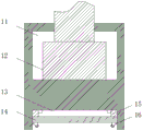
Fig. 2 is a schematic view of the sectional structure of the box body a of the present invention.
Fig. 3 is a schematic view of the sectional structure of the hanging rack of the present invention.
Fig. 4 is a schematic view of the structure of the support plate according to the present invention.
1-a cross beam; 2. an electric hoist; 3. a bracket A; 4. a box body A; 5. a control panel; 6. a box door; 7. a support plate; 8. a hook; 9. a bracket B; 10. a box body B; 11. an upper inner cavity; 12. an electromagnetic lifting column A; 13. a lower inner cavity; 14. a base; 15. an electromagnetic lifting column B; 16. a mounting seat; 17. A roller; 18. a tooth socket; 19. a motor; 20. a hanger; 21. a slot; 22. a bulb; 23-lampshade.
Detailed Description
In order to make the objects, technical solutions and advantages of the present invention more clearly understood, the present invention is further described in detail below with reference to the accompanying drawings and embodiments. It should be understood that the specific embodiments described herein are merely illustrative of the invention and are not intended to limit the invention.
Example 1
As shown in fig. 1 to 4, a construction equipment for electromechanical engineering, comprising a beam 1, an electric elevator 2, a bracket A3, a box a4, a control panel 5, a door 6, a supporting plate 7, a hook 8, a bracket B9, a box B10, an upper cavity 11, an electromagnetic lifting column a12, a lower cavity 13, a base 14, an electromagnetic lifting column B15, a mounting seat 16, a roller 17, a tooth groove 18, a motor 19, a hanger 20, a hole groove 21, a bulb 22 and a lamp cover 23, wherein the beam 1 is mounted on the bracket A3 and the bracket B9, the bracket A3 is disposed on the left side of the beam 1, the supporting plate 7 is disposed between the bracket A3 and the beam 1, the bracket A3 is disposed on the upper surface of the box a4, the bracket B9 is disposed on the right side of the beam 1, the supporting plate 7 is disposed between the bracket B9 and the beam 1, the bracket B9 is mounted on the upper surface of the box B10, the head end of box A4 is provided with control panel 5, box A4 with the right side of box B10 is provided with chamber door 6, the lower extreme of crossbeam 1 intermediate position is provided with electric lift 2, just be provided with on the electric lift 2 lifting hook 8, the inside of box A4 is provided with go up inner chamber 11, just install in going up inner chamber 11 electromagnetism lift post A12, the lower extreme of going up inner chamber 11 is provided with lower inner chamber 13, just install in lower inner chamber 13 electromagnetism lift post B15, electromagnetism lift post B15 has four, the one end of electromagnetism lift post B15 is fixed on base 14, base 14 sets up in lower inner chamber 13, the lower fixed surface of base 14 has mount pad 16, install between crossbeam 1 and the electric lift 2 hanger 20, hanger 20 is installed on crossbeam 1, just stores pylon 20 with install between crossbeam 1 gyro wheel 17, install the intermediate position of crossbeam 1 lower surface tooth's socket 18, install on the stores pylon 20 motor 19, just motor 19's head end with tooth's socket 18 is connected, electric lift 2 installs the lower surface of stores pylon 20, be provided with on the backup pad 7 hole groove 21, just install in the hole groove 21 bulb 22, install on the hole groove 21 lamp shade 23.
More specifically, the hinges are arranged between the box bodies A4 and B10 and the box door 6, the handle is arranged on the box door 6, so that the equipment is convenient to overhaul and check, and the universal wheels are arranged on the lower surface of the mounting seat 16, so that the equipment is convenient to move.
Example 2
As shown in fig. 1-3, electric lift 2 with pass through between the lifting hook 8 wire rope connects, install the head end of motor 19 the gear, the gear with tooth's socket 18 is connected, motor 19's model is CH22400W30SBG1 LB.
The utility model discloses improve in: the utility model provides a construction equipment for electromechanical engineering, the removal of this kind of equipment can be realized to the universal wheel through box A4 and box B10 bottom, tooth's socket 18 design on this kind of equipment crossbeam 1 is convenient for electric lift 2 controls and removes simultaneously, position control when doing benefit to the installation of hanging the thing, the structural strength of this kind of equipment is convenient for improve in the design of backup pad 7, the bulb 22 design on the backup pad 7 does benefit to the illumination of this kind of equipment during operation night, the design of chamber door 6 is of value to and inspects and maintains the inside equipment of box A4 and box B10.
The above-described embodiments are merely illustrative of the preferred embodiments of the present invention and are not intended to limit the spirit and scope of the present invention. Without departing from the design concept of the present invention, various modifications and improvements made by the technical solution of the present invention by those skilled in the art should fall into the protection scope of the present invention, and the technical contents claimed by the present invention have been fully recorded in the claims.
Claims (6)
1. The utility model provides a construction equipment for electromechanical engineering, including crossbeam (1), electric lift (2), support A (3), box A (4), control panel (5), chamber door (6), backup pad (7), lifting hook (8), support B (9), box B (10), go up inner chamber (11), electromagnetism lift post A (12), lower inner chamber (13), base (14), electromagnetism lift post B (15), mount pad (16), gyro wheel (17), tooth's socket (18), motor (19), stores pylon (20), hole groove (21), bulb (22) and lamp shade (23), its characterized in that: the beam (1) is arranged on the support A (3) and the support B (9), the support A (3) is arranged on the left side of the beam (1), the support plate (7) is arranged between the support A (3) and the beam (1), the support A (3) is arranged on the upper surface of the box body A (4), the support B (9) is arranged on the right side of the beam (1), the support plate (7) is arranged between the support B (9) and the beam (1), the support B (9) is arranged on the upper surface of the box body B (10), the head end of the box body A (4) is provided with the control panel (5), the right sides of the box body A (4) and the box body B (10) are provided with the box door (6), the lower end of the middle position of the beam (1) is provided with the electric elevator (2), the lifting hook (8) is arranged on the electric elevator (2), the upper inner cavity (11) is arranged in the box body A (4), the electromagnetic lifting columns A (12) are arranged in the upper inner cavity (11), the lower end of the upper inner cavity (11) is provided with the lower inner cavity (13), the electromagnetic lifting columns B (15) are arranged in the lower inner cavity (13), the number of the electromagnetic lifting columns B (15) is four, one end of each electromagnetic lifting column B (15) is fixed on the base (14), the base (14) is arranged in the lower inner cavity (13), the mounting seat (16) is fixed on the lower surface of the base (14), the hanging rack (20) is arranged between the beam (1) and the electric elevator (2), the hanging rack (20) is arranged on the beam (1), and the idler wheels (17) are arranged between the hanging rack (20) and the beam (1), install the intermediate position of crossbeam (1) lower surface tooth's socket (18), install on stores pylon (20) motor (19), just the head end of motor (19) with tooth's socket (18) are connected, electric lift (2) are installed the lower surface of stores pylon (20), be provided with on backup pad (7) hole groove (21), just install in hole groove (21) bulb (22), install on hole groove (21) lamp shade (23).
2. The construction equipment for electromechanical engineering according to claim 1, characterized in that: a hinge is arranged between the box body A (4) and the box body B (10) and the box door (6), and a handle is arranged on the box door (6).
3. The construction equipment for electromechanical engineering according to claim 1, characterized in that: the lower surface of the mounting seat (16) is provided with a universal wheel.
4. The construction equipment for electromechanical engineering according to claim 1, characterized in that: the electric elevator (2) is connected with the lifting hook (8) through a steel wire rope.
5. The construction equipment for electromechanical engineering according to claim 1, characterized in that: the head end of the motor (19) is provided with a gear, and the gear is connected with the tooth groove (18).
6. The construction equipment for electromechanical engineering according to claim 1, characterized in that: the model of the motor (19) is CH22400W30SBG1 LB.
Priority Applications (1)
| Application Number | Priority Date | Filing Date | Title |
|---|---|---|---|
| CN201921278589.6U CN210683045U (en) | 2019-08-08 | 2019-08-08 | Construction equipment for electromechanical engineering |
Applications Claiming Priority (1)
| Application Number | Priority Date | Filing Date | Title |
|---|---|---|---|
| CN201921278589.6U CN210683045U (en) | 2019-08-08 | 2019-08-08 | Construction equipment for electromechanical engineering |
Publications (1)
| Publication Number | Publication Date |
|---|---|
| CN210683045U true CN210683045U (en) | 2020-06-05 |
Family
ID=70896222
Family Applications (1)
| Application Number | Title | Priority Date | Filing Date |
|---|---|---|---|
| CN201921278589.6U Expired - Fee Related CN210683045U (en) | 2019-08-08 | 2019-08-08 | Construction equipment for electromechanical engineering |
Country Status (1)
| Country | Link |
|---|---|
| CN (1) | CN210683045U (en) |
-
2019
- 2019-08-08 CN CN201921278589.6U patent/CN210683045U/en not_active Expired - Fee Related
Similar Documents
| Publication | Publication Date | Title |
|---|---|---|
| CN205114894U (en) | Manual formula wall type swing crane; derrick | |
| CN210683045U (en) | Construction equipment for electromechanical engineering | |
| CN210162191U (en) | Power battery and automobile body dismouting mechanism | |
| CN204455739U (en) | High-speed switch is grown up part replacement special purpose device | |
| CN204400421U (en) | A kind of gallows frame adopting electromagnet | |
| JP2008222382A (en) | Method for moving lifting device for installation | |
| CN202449763U (en) | Simple pneumatic crane | |
| CN218708748U (en) | Cement pole hoist and mount transportation integrated device | |
| US7562430B2 (en) | Pin changing device and method | |
| CN203754298U (en) | Vehicle-mounted hoisting device | |
| CN111302201A (en) | Self-walking mechanical equipment lifting frame | |
| CN101660660A (en) | Novel installing method of gas cabinet | |
| CN204866387U (en) | A equip for bearing roller spraying | |
| CN205257816U (en) | Be used for lifting machine in wind generating set cabin | |
| CN202369291U (en) | Winch mounting structure of automobile crane | |
| CN214243530U (en) | Electric power vase crane equipment | |
| CN213771063U (en) | Hoisting mechanism for mounting mine electromechanical equipment | |
| CN211004230U (en) | Special motor hoisting tool for equipment maintenance of cigarette machine | |
| CN214828524U (en) | Portable assembled building board hoist device | |
| CN212127339U (en) | Curtain fortune dimension overhead hoist for building | |
| CN203833501U (en) | Stretchable rod and crane with stretchable rod | |
| CN217413051U (en) | Be used for coal-winning machine frame processing to use auxiliary fixtures | |
| CN202322080U (en) | Moisture separator reheater assembly hanger | |
| CN218174475U (en) | Construction building suspension | |
| CN210029951U (en) | Portable hanging flower basket is used in illumination engineering construction |
Legal Events
| Date | Code | Title | Description |
|---|---|---|---|
| GR01 | Patent grant | ||
| GR01 | Patent grant | ||
| CF01 | Termination of patent right due to non-payment of annual fee | ||
| CF01 | Termination of patent right due to non-payment of annual fee |
Granted publication date: 20200605 Termination date: 20210808 |