CN2107724U - Junction Box - Google Patents
Junction Box Download PDFInfo
- Publication number
- CN2107724U CN2107724U CN 91226339 CN91226339U CN2107724U CN 2107724 U CN2107724 U CN 2107724U CN 91226339 CN91226339 CN 91226339 CN 91226339 U CN91226339 U CN 91226339U CN 2107724 U CN2107724 U CN 2107724U
- Authority
- CN
- China
- Prior art keywords
- junction box
- fixing
- cabling pipe
- pipe box
- hole
- Prior art date
- Legal status (The legal status is an assumption and is not a legal conclusion. Google has not performed a legal analysis and makes no representation as to the accuracy of the status listed.)
- Granted
Links
- 239000004567 concrete Substances 0.000 claims abstract description 14
- RYGMFSIKBFXOCR-UHFFFAOYSA-N Copper Chemical compound [Cu] RYGMFSIKBFXOCR-UHFFFAOYSA-N 0.000 claims abstract description 5
- 229910052802 copper Inorganic materials 0.000 claims abstract description 5
- 239000010949 copper Substances 0.000 claims abstract description 5
- 238000001746 injection moulding Methods 0.000 claims abstract description 4
- 238000000034 method Methods 0.000 claims abstract description 4
- 238000009434 installation Methods 0.000 claims description 7
- 238000004519 manufacturing process Methods 0.000 claims description 3
- 230000002787 reinforcement Effects 0.000 claims description 3
- 210000003205 muscle Anatomy 0.000 claims 2
- 208000005189 Embolism Diseases 0.000 claims 1
- 238000007789 sealing Methods 0.000 abstract description 13
- 239000002002 slurry Substances 0.000 abstract description 9
- 230000035515 penetration Effects 0.000 abstract 1
- 229920003023 plastic Polymers 0.000 description 6
- 239000004033 plastic Substances 0.000 description 6
- XEEYBQQBJWHFJM-UHFFFAOYSA-N Iron Chemical compound [Fe] XEEYBQQBJWHFJM-UHFFFAOYSA-N 0.000 description 5
- 238000009415 formwork Methods 0.000 description 4
- 229910052742 iron Inorganic materials 0.000 description 3
- 230000000149 penetrating effect Effects 0.000 description 3
- 238000010276 construction Methods 0.000 description 2
- JEIPFZHSYJVQDO-UHFFFAOYSA-N iron(III) oxide Inorganic materials O=[Fe]O[Fe]=O JEIPFZHSYJVQDO-UHFFFAOYSA-N 0.000 description 2
- 230000003014 reinforcing effect Effects 0.000 description 2
- 230000000903 blocking effect Effects 0.000 description 1
- 230000007547 defect Effects 0.000 description 1
- 239000011440 grout Substances 0.000 description 1
- 238000011065 in-situ storage Methods 0.000 description 1
- 150000002505 iron Chemical class 0.000 description 1
- 239000000463 material Substances 0.000 description 1
- 229920000915 polyvinyl chloride Polymers 0.000 description 1
- 239000004800 polyvinyl chloride Substances 0.000 description 1
- 238000002360 preparation method Methods 0.000 description 1
- 239000011150 reinforced concrete Substances 0.000 description 1
Images

Landscapes
- Connection Or Junction Boxes (AREA)
- Laying Of Electric Cables Or Lines Outside (AREA)
Abstract
Description
本实用新型涉及接线盒,尤其涉及在建筑工业中嵌埋在混凝土或钢筋混凝土墙壁或楼板内的供暗线连接使用的接线盒。The utility model relates to a junction box, in particular to a junction box embedded in concrete or reinforced concrete walls or floor slabs for concealed wire connection in the construction industry.
在建筑工业中,将接线盒嵌埋在现浇或预制的墙壁或楼板内以实现暗线连接或安装电气开关或其他组件的技术早已成公知。最早使用的是用铁皮制造的接线盒,这种铁盒的缺点是容易锈蚀,其翻边制出的螺纹孔很容易滑扣,而且容易变形而导致外装组件定位不准,影响美观;而且没有设置固定到模板上的装置,因此无法准确地在模板上固定就位,必须外加诸如固定卡子之类的配件才能将接线盒固定到模板上,不但需要外加配件,而且很不容易找准固定位置,费时失事。经过改进,设计出以强度较高的改性聚氯乙烯为原料制出的塑料接线盒。有代表性的是英国Ega公司的产品。这种塑料接线盒虽然消除了铁皮接线盒的锈蚀与容易变形的缺点,但是其加长了的塑料螺纹部份仍然不够坚固,同时本身没法在模板上定位的问题仍然存在。虽然这种塑料接线盒在制出状态时在穿线孔部位上带有原旨在浇灌混凝土时防止混凝土浆渗入走线管的可去除的封口板,但是在为了方便走线而加装了外加的走线管套筒后,封口板就去掉了。这样,混凝土浆就会在浇灌时渗入走线管内。要防止这个现象出现就要采取另外的堵口措施,这就直接加长准备工作时间,既费工又费料,增大了生产成本。Embedding junction boxes in cast-in-situ or prefabricated walls or floors for concealed wiring or for installing electrical switches or other components has long been known in the construction industry. The earliest use was the junction box made of iron sheet. The disadvantage of this iron box is that it is easy to rust, and the threaded hole made by the flange is easy to slip and buckle, and it is easy to deform, which leads to inaccurate positioning of the external components and affects the appearance; and there is no Set the device fixed on the formwork, so it cannot be accurately fixed in place on the formwork, and accessories such as fixing clips must be added to fix the junction box to the formwork. Not only does it require additional accessories, but it is also very difficult to find the fixing position , time-consuming accident. After improvement, a plastic junction box made of high-strength modified polyvinyl chloride was designed. Representative is the product of British Ega company. Although this plastic junction box eliminates the rust and easy deformation of the iron junction box, the lengthened plastic thread part is still not strong enough, and the problem that it cannot be positioned on the template still exists. Although this kind of plastic junction box has a detachable sealing plate originally intended to prevent the concrete slurry from penetrating into the wiring pipe when it is poured in the wiring hole when it is produced, but an additional sealing plate is installed for the convenience of wiring. After the cable tube is sleeved, the sealing plate is removed. In this way, the concrete slurry will seep into the conduit when pouring. To prevent this phenomenon from occurring, additional blocking measures will be taken, which will directly lengthen the preparation time, which takes a lot of labor and materials, and increases the production cost.
本实用新型的目的在于提供一种定位操作方便、保证防止混凝土浆在浇灌时进入走线管内的、浇定后对外安装组件配合要求比较低而且设有便于准确地固定就位的设施的接线盒。The purpose of this utility model is to provide a junction box that is convenient for positioning and operation, ensures that the concrete slurry is prevented from entering the wiring pipe during pouring, has relatively low requirements for the cooperation of externally installed components after pouring, and is equipped with facilities that facilitate and accurately fix in place .
本实用新型在结构上采取下列措施以实现上述目标。首先是将走线管套筒整体地制出在接线盒本体上,在走线管套筒外缘上设置了加强筋以进行加固,在其与接线盒本体交接处设置可去除的封口板以防止混凝土浆在浇灌时渗入走线管。在本体外面设有作为固定装置的带孔凸耳以便于用钉子之类将接线盒准确地固定就位在模板上,并设凸筋以增强凸耳。采用外加活动铜螺帽带间隙地装入外装组件安装孔内并在背后用栓塞堵住,以便利安装调整从而改善安装定位的准确性进而保证整齐美现,以及防止浇灌时混凝土浆从背面渗入。这样的结构改进一举基本上解决了这种嵌埋式接线盒一直存在着的问题,降低了生产成本。同时,接线盒的走线管套筒、固定凸耳及安装外装组件的固定柱装置的数目与设置位置的排列组合可按要求来提供,以适应不同的使用情况。The utility model takes the following measures structurally to achieve the above object. Firstly, the wiring tube sleeve is integrally made on the junction box body, and reinforcing ribs are set on the outer edge of the wiring tube sleeve for reinforcement, and a removable sealing plate is set at the junction of the wiring tube sleeve and the junction box body to Prevent concrete slurry from penetrating into the conduit during pouring. There are lugs with holes as a fixing device on the outside of the body so that the junction box can be accurately fixed on the template with nails or the like, and ribs are provided to strengthen the lugs. Use additional movable copper nuts to fit into the mounting holes of the exterior components with gaps and block them with plugs at the back to facilitate installation and adjustment, improve the accuracy of installation positioning, ensure neat and beautiful appearance, and prevent concrete slurry from seeping in from the back when pouring . This kind of structural improvement basically solves the problems that have always existed in this embedded junction box at one stroke, and reduces the production cost. At the same time, the arrangement and combination of the number and installation positions of the wiring tube sleeves of the junction box, the fixing lugs and the fixing column devices for installing the external components can be provided according to requirements, so as to adapt to different usage situations.
现结合附图对本实用新型进行详细的说明。在附图中,Now in conjunction with accompanying drawing, the utility model is described in detail. In the attached picture,
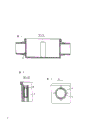
图1是先有技术的接线盒本体装有两个外加导线套筒后的俯视图,Fig. 1 is the top view of the junction box body of the prior art after two additional wire sleeves are housed,
图2是沿图1的Ⅰ-Ⅰ线切取的先有技术接线盒的剖视图,Fig. 2 is a cross-sectional view of a prior art junction box taken along line I-I of Fig. 1,
图3是沿图1的Ⅱ-Ⅱ线切取的外装组件安装孔的局部剖视图,Fig. 3 is a partial cross-sectional view of the mounting hole of the exterior assembly taken along the line II-II of Fig. 1,
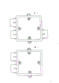
图4是本实用新型的接线盒的第一实施例的俯视图,Fig. 4 is the top view of the first embodiment of the junction box of the present utility model,
图5是沿图4的Ⅴ-Ⅴ线切取的接线盒的半剖视图,Fig. 5 is a half-sectional view of the junction box taken along the line V-V of Fig. 4,
图6是沿图4的Ⅵ-Ⅵ线切取的外装组件安装孔的局部剖视图,Fig. 6 is a partial cross-sectional view of the installation hole of the exterior assembly taken along the line VI-VI of Fig. 4,
图7是沿图4的箭头A看的视图,示出封口板的连筋与圆弧形槽缝,Fig. 7 is the view seen along the arrow A of Fig. 4, shows the connecting rib and the arc-shaped slot of the sealing plate,
图8是本实用新型的接线盒的第二实施例的俯视图,Fig. 8 is a top view of the second embodiment of the junction box of the present invention,
图9是本实用新型的接线盒的第三实施例的俯视图,Fig. 9 is a top view of a third embodiment of the junction box of the present invention,
图10是本实用新型的接线盒的第四实施例的俯视图,Fig. 10 is a top view of the fourth embodiment of the junction box of the present utility model,
图11是本实用新型的接线盒的第五实施例的俯视图。Fig. 11 is a top view of the fifth embodiment of the junction box of the present invention.
图1、2与3示出先有技术的接线盒。从图1与2中可见,走线管套筒跟本体是两个部件。从图2可见,在左侧没有使用的出口上还带有封口板,而在右侧的装上走线管套筒的出口就不再存在封口板了,这就不能保证在浇灌时混凝土浆不会进入走线管内。图3示出与塑料本体一体制出的外装组件安装螺孔的情况,主要说明安装螺孔是塑料螺孔。Figures 1, 2 and 3 show a prior art junction box. It can be seen from Figures 1 and 2 that the cable conduit sleeve and the body are two parts. It can be seen from Figure 2 that there is a sealing plate on the unused outlet on the left side, and there is no sealing plate on the outlet on the right side where the wire pipe sleeve is installed, which cannot guarantee the concrete grout when pouring. will not enter the conduit. Fig. 3 shows the situation of the mounting screw holes of the exterior assembly manufactured integrally with the plastic body, mainly indicating that the mounting screw holes are plastic screw holes.
图4、5与6示出本实用新型的接线盒的第一实施例。在这个第一实施例中,接线盒本体1与四个走线管套筒2一起用注塑方法或其它方法一体成形。从图5可见,走线管套筒孔与本体侧壁交接处设有封口板3,使此接线盒在浇灌时保证混凝土浆不会渗入走线管内。此封口板通过三条或四条狭窄的连筋4跟本体侧壁连在一起用注塑或其它方法制出,为便于在浇灌后将封口板去除而设的、其外圆与套筒孔径相应的圆弧形槽缝5是为了描绘清楚而夸大地画出(见图7)。走线管套筒在外周上设有加强筋6。从图6可见,本体的安装外装组件的固定柱7内具有一个六角形深孔,其内带间隙地装有一个六方铜螺帽8以保证安装外装组件时不容易滑扣,然后用封端的栓塞9封住以防止混凝土浆在浇灌时渗入螺帽的螺纹内。六角形孔跟六方铜螺帽的带有间隙的配合,保证在即使在浇灌时本体有些微移动也能使外装组件按所需位置、保持美观整齐地准确地安装。从图4可见,为将接线盒固定到模板上而设的带孔凸耳10设在本体外侧,加上加强筋来加强,这就解决了先有技术的接线盒自身不能可靠而准确地固定就位在模板上的问题。4, 5 and 6 show the first embodiment of the junction box of the present invention. In this first embodiment, the junction box body 1 and the four conduit sleeves 2 are integrally formed by injection molding or other methods. It can be seen from Fig. 5 that a sealing plate 3 is provided at the junction of the sleeve hole of the wiring pipe and the side wall of the main body, so that the junction box can ensure that the concrete slurry will not penetrate into the wiring pipe when pouring. The sealing plate is connected with the side wall of the main body through three or four narrow connecting
图8至图11分别示出本实用新型的接线盒的具有三个、两个或单个走线管套筒的第二至第五实施例。结构完全一样,只是伸出的走线管套筒的数目与设置位置不同而已。8 to 11 respectively show the second to fifth embodiments of the junction box of the present invention with three, two or single conduit sleeves. The structure is exactly the same, only the number and setting positions of the protruding wire tube sleeves are different.
综上所述,本实用新型基本上消除了这种类型的先有技术接线盒的所用缺陷,提供一种比较完善的嵌埋式接线盒。当然这种接线盒的用途不局限于嵌埋在混凝土墙壁或楼板内,也可以装在有吊顶的楼顶上来作管道走线的接线盒使用。当然也可以用于不要求外观美观的工业厂房或机房内作为明线走线的接线盒使用。To sum up, the utility model basically eliminates all the defects of this type of junction box in the prior art, and provides a relatively complete embedded junction box. Of course, the use of this junction box is not limited to being embedded in concrete walls or floors, and it can also be installed on the roof with a suspended ceiling to be used as a junction box for pipeline routing. Of course, it can also be used as a junction box for open wiring in industrial plants or machine rooms that do not require a beautiful appearance.
Claims (1)
Priority Applications (1)
| Application Number | Priority Date | Filing Date | Title |
|---|---|---|---|
| CN 91226339 CN2107724U (en) | 1991-10-04 | 1991-10-04 | Junction Box |
Applications Claiming Priority (1)
| Application Number | Priority Date | Filing Date | Title |
|---|---|---|---|
| CN 91226339 CN2107724U (en) | 1991-10-04 | 1991-10-04 | Junction Box |
Publications (1)
| Publication Number | Publication Date |
|---|---|
| CN2107724U true CN2107724U (en) | 1992-06-17 |
Family
ID=4932443
Family Applications (1)
| Application Number | Title | Priority Date | Filing Date |
|---|---|---|---|
| CN 91226339 Granted CN2107724U (en) | 1991-10-04 | 1991-10-04 | Junction Box |
Country Status (1)
| Country | Link |
|---|---|
| CN (1) | CN2107724U (en) |
Cited By (2)
| Publication number | Priority date | Publication date | Assignee | Title |
|---|---|---|---|---|
| CN105071302A (en) * | 2015-07-15 | 2015-11-18 | 中国十七冶集团有限公司 | Junction box concealed burying accurate positioning method |
| CN108233297A (en) * | 2018-01-31 | 2018-06-29 | 丁德成 | One kind integrates anti-blocking pre-buried Built-in terminal box |
-
1991
- 1991-10-04 CN CN 91226339 patent/CN2107724U/en active Granted
Cited By (2)
| Publication number | Priority date | Publication date | Assignee | Title |
|---|---|---|---|---|
| CN105071302A (en) * | 2015-07-15 | 2015-11-18 | 中国十七冶集团有限公司 | Junction box concealed burying accurate positioning method |
| CN108233297A (en) * | 2018-01-31 | 2018-06-29 | 丁德成 | One kind integrates anti-blocking pre-buried Built-in terminal box |
Similar Documents
| Publication | Publication Date | Title |
|---|---|---|
| US6586679B2 (en) | Electrical junction box for construction panels | |
| US20010023772A1 (en) | Embeddable mounting device | |
| US2775017A (en) | Concrete form structure | |
| KR20190019449A (en) | Distribution Panel for Easy Wall Distance Adjustment | |
| CN2107724U (en) | Junction Box | |
| CN2155638Y (en) | Junction box with large interior space | |
| KR200486198Y1 (en) | Cable Wiring Hose Support Bar | |
| CA2028929C (en) | Electric junction box/outlet | |
| CN211313074U (en) | Integrated building external wall panel convenient to install | |
| CN210659286U (en) | Extension box of junction box | |
| KR19990030579A (en) | Electrical piping box for ceiling slab | |
| CN223536259U (en) | A prefabricated building waterproof sealing device | |
| KR200286055Y1 (en) | Anchor bolt fastener and spacer for reinforcement bar arrangement of building | |
| CN217734659U (en) | A prefabricated panel system | |
| CN215772427U (en) | Pipeline erecting device for assembled wall | |
| CN212897328U (en) | Assembled steel construction building externally-hung wallboard | |
| KR920004941Y1 (en) | Connection device of pipe box for conduit | |
| CN216720766U (en) | Building machine electric pipeline construction equipment | |
| CN215630829U (en) | Shaping structure for wall body precast | |
| CN2099401U (en) | installation box | |
| JP3075147U (en) | Cover with wall buried piping drawer fixture | |
| CN215167172U (en) | Prefabricated wallboard structure with embedded wire pipe and embedded wire box | |
| JPH0629285Y2 (en) | insert | |
| JPH043543Y2 (en) | ||
| JPH04774Y2 (en) |
Legal Events
| Date | Code | Title | Description |
|---|---|---|---|
| C06 | Publication | ||
| PB01 | Publication | ||
| C14 | Grant of patent or utility model | ||
| GR01 | Patent grant | ||
| C15 | Extension of patent right duration from 15 to 20 years for appl. with date before 31.12.1992 and still valid on 11.12.2001 (patent law change 1993) | ||
| RN01 | Renewal of patent term | ||
| C19 | Lapse of patent right due to non-payment of the annual fee | ||
| CF01 | Termination of patent right due to non-payment of annual fee | ||
| C35 | Partial or whole invalidation of patent or utility model | ||
| IW01 | Full invalidation of patent right |
Decision date of declaring invalidation: 19990212 Decision number of declaring invalidation: 1261 |