CN210802436U - Clamp for measuring roughness of special-shaped roller - Google Patents
Clamp for measuring roughness of special-shaped roller Download PDFInfo
- Publication number
- CN210802436U CN210802436U CN201921361933.8U CN201921361933U CN210802436U CN 210802436 U CN210802436 U CN 210802436U CN 201921361933 U CN201921361933 U CN 201921361933U CN 210802436 U CN210802436 U CN 210802436U
- Authority
- CN
- China
- Prior art keywords
- positioning block
- block
- movable seat
- special
- clamping slide
- Prior art date
- Legal status (The legal status is an assumption and is not a legal conclusion. Google has not performed a legal analysis and makes no representation as to the accuracy of the status listed.)
- Active
Links
- 238000004439 roughness measurement Methods 0.000 claims abstract description 8
- 238000012360 testing method Methods 0.000 claims description 9
- 206010066054 Dysmorphism Diseases 0.000 claims description 3
- 238000001514 detection method Methods 0.000 description 6
- 238000005259 measurement Methods 0.000 description 5
- 239000000523 sample Substances 0.000 description 5
- 230000003746 surface roughness Effects 0.000 description 4
- 238000000034 method Methods 0.000 description 3
- 230000008859 change Effects 0.000 description 2
- 238000010586 diagram Methods 0.000 description 2
- 238000004519 manufacturing process Methods 0.000 description 2
- 238000012986 modification Methods 0.000 description 2
- 230000004048 modification Effects 0.000 description 2
- 238000012545 processing Methods 0.000 description 2
- 230000009471 action Effects 0.000 description 1
- 230000009286 beneficial effect Effects 0.000 description 1
- 238000004891 communication Methods 0.000 description 1
- 238000005516 engineering process Methods 0.000 description 1
- 230000006872 improvement Effects 0.000 description 1
- 230000001788 irregular Effects 0.000 description 1
- 239000000463 material Substances 0.000 description 1
- 229910052755 nonmetal Inorganic materials 0.000 description 1
Images

Landscapes
- A Measuring Device Byusing Mechanical Method (AREA)
Abstract
The utility model discloses a special-shaped roller roughness measurement clamp, which comprises a base, wherein a movable seat capable of moving left and right relative to the base is arranged above the base, and a clamping slide block capable of moving left and right relative to the movable seat is arranged above the movable seat; one end of the movable seat is provided with a supporting plate, one side of the supporting plate, which is opposite to the clamping slide block, is provided with a first positioning block, one end, which is opposite to the first positioning block, of the clamping slide block is provided with a second positioning block, and the first positioning block and the second positioning block jointly act to position the special-shaped roller to be measured; a tension spring which can pull the clamping slide block to move towards one side of the second positioning block all the time to clamp the special-shaped roller is connected between the movable seat and the clamping slide block, and an adjusting rod which is abutted against the clamping slide block and used for adjusting the distance between the first positioning block and the second positioning block is further arranged on the supporting plate. The clamp is suitable for the special-shaped rollers with different lengths, can firmly clamp the special-shaped rollers to conveniently measure the roughness, and is convenient to adjust the position and operate.
Description
Technical Field
The utility model belongs to the technical field of measure the technique and specifically relates to a dysmorphism roller roughness measurement is with anchor clamps are related to.
Background
At present, the surface roughness has close relation with the matching property, wear resistance, fatigue strength, contact rigidity, vibration, noise and the like of mechanical parts, and has important influence on the service life and reliability of mechanical products. In order to ensure the quality of mechanical parts, the surface roughness of the parts needs to be tested, and workers generally use a roughness tester to measure the roughness of each surface of the parts to visually obtain the result of whether the product roughness is qualified.
With the continuous enhancement and improvement of the technology and the function of the roughness meter and the deep popularization and application, more and more industries use the roughness meter to carry out detection, and the application fields comprise the mechanical processing and manufacturing industry, the non-metal processing and manufacturing industry, the electric power industry, the communication industry, the electronic industry and the like. The roughness meter sold in the market at present adopts a V-shaped block or a cross double-guide-rail high-precision measuring platform, but is limited by a platform structure, only certain structural rule parts can be positioned and detected, when some special-shaped small-sized precision parts (such as special-shaped rollers) are subjected to roughness measurement, the special-shaped small-sized precision parts are usually adhered to the general platform of the roughness meter by adopting plasticine, and the measurement can be carried out only by repeatedly adjusting the position and the inclination angle of a workpiece.
Therefore, the conventional roughness meter is difficult to realize convenient and accurate positioning measurement on the special-shaped roller produced by the company, and needs a roughness measuring clamp which can be suitable for the special-shaped rollers with various sizes and can be conveniently and quickly adjusted.
SUMMERY OF THE UTILITY MODEL
In view of this, the utility model aims at providing an anchor clamps are used in special-shaped roller roughness measurement, this anchor clamps are applicable to the special-shaped roller of different length, can realize firmly measuring roughness with the convenience to the special-shaped roller clamping, and position adjustment is convenient, the simple operation.
The utility model discloses a solve the technical scheme that above-mentioned technical problem adopted and be: the clamp for measuring the roughness of the special-shaped roller comprises a base detachably connected with a workbench of a roughness meter, a movable seat capable of moving left and right relative to the base is arranged above the base, and a clamping slide block capable of moving left and right relative to the movable seat is arranged above the movable seat; one end of the movable seat is provided with a supporting plate, one side of the supporting plate, which is opposite to the clamping slide block, is provided with a first positioning block, one end, which is opposite to the first positioning block, of the clamping slide block is provided with a second positioning block, and the first positioning block and the second positioning block jointly act to position the special-shaped roller to be measured; a tension spring which can pull the clamping slide block to move towards one side of the second positioning block all the time to clamp the special-shaped roller is connected between the movable seat and the clamping slide block, and an adjusting rod which is abutted against the clamping slide block and used for adjusting the distance between the first positioning block and the second positioning block is further arranged on the supporting plate.
Furthermore, the upper part of the base is provided with a groove III, and the inner sides of two side walls extending along the left-right direction at the top of the groove III are symmetrically provided with slide rails; an auxiliary sliding block is arranged in the groove III, and sliding strips matched with the sliding rails are arranged on two corresponding side walls of the auxiliary sliding block; the auxiliary sliding block is in threaded connection with a lead screw, a hand wheel is arranged at one end, away from the auxiliary sliding block, of the lead screw, the lead screw can drive the auxiliary sliding block to move left and right along the base through rotating the hand wheel, and the auxiliary sliding block is detachably connected with a movable seat located above the auxiliary sliding block.
Furthermore, a groove I is formed in the upper portion of the movable seat, and a longitudinal rod I extending in the longitudinal direction is arranged at one end, close to the supporting plate, in the groove I; a groove II opposite to and communicated with the opening of the groove I is formed in the lower part of the clamping sliding block, and a longitudinal rod II parallel to the longitudinal rod I is arranged at one end, far away from the second positioning block, in the groove II; the longitudinal rod I and the longitudinal rod II are connected with tension springs.
Furthermore, the first positioning block is detachably connected with the supporting plate; the second positioning block is detachably connected with the clamping slide block.
Furthermore, the top of two side walls of the movable seat perpendicular to the supporting plate is provided with a sliding groove, and the bottom of the corresponding side wall of the clamping sliding block is provided with a guide rail strip matched with the sliding groove so that the clamping sliding block can move left and right relative to the movable seat.
Furthermore, the first positioning block and the second positioning block are both provided with limiting grooves with the shape consistent with the shape of the non-testing surface of the special-shaped roller.
Furthermore, the adjusting rod is a fine-tooth screw rod.
Has the advantages that:
as described above, the utility model discloses an anchor clamps for special-shaped roller roughness measurement has following beneficial effect:
1. the clamp is provided with a movable seat capable of moving left and right relative to the base, and the position of the special-shaped roller relative to the test probe of the roughness measuring instrument can be adjusted by moving the movable seat, so that the surface roughness of the special-shaped roller at different positions can be measured; by arranging the tension spring and the adjusting rod, the special-shaped rollers with different lengths can be clamped by the first positioning block and the second positioning block, the tension spring is adopted to provide clamping force, the strength is moderate, the special-shaped rollers can be prevented from being clamped, the tension spring is tensioned downwards, and the clamping slide block is prevented from tilting when the special-shaped rollers are clamped; the special-shaped roller can automatically return by virtue of the tension spring, and after detection is finished, the special-shaped roller can be detached only by rotating the adjusting rod to enable the clamping slide block to slightly displace; the whole structure is simple, the operation is convenient, and the use is reasonable.
2. The first locating block and the second locating block of the clamp are respectively provided with a limiting groove which is consistent with the shape of the non-testing surface of the special-shaped roller, the limiting grooves are used for controlling the fixed corner of the special-shaped roller, the purpose of circumferentially locating the special-shaped roller is achieved, the measuring angle of the locating block without adjusting the roller is set, the locating is accurate, the use is convenient, and the detection efficiency is improved.
3. The adjusting rod of the clamp adopts a fine-tooth screw rod, so that the moving stroke of the sliding block can be reduced when the special-shaped rollers with different lengths are assembled and disassembled in batch detection.
The present invention will be described in further detail with reference to the drawings and specific examples.
Drawings
In order to more clearly illustrate the embodiments of the present invention or the technical solutions in the prior art, the drawings used in the embodiments or the prior art will be briefly described below, and it is obvious that the drawings in the following description are only some embodiments of the present invention, and for those skilled in the art, other drawings can be obtained according to these drawings without creative efforts.
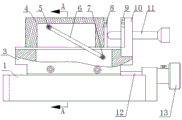
Fig. 1 is a schematic structural diagram of the present invention.
Fig. 2 is a cross-sectional view at a-a in fig. 1.
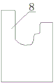
Fig. 3 is a schematic structural diagram of the second positioning block of the present invention.
The device comprises a graphic mark 1, a base 2, an auxiliary sliding block 3, a movable seat 301, a groove I, 4, a clamping sliding block 401, a groove II, 5, a longitudinal rod II, 6, a tension spring 7, a longitudinal rod I, 8, a second positioning block 9, a first positioning block 10, a supporting plate 11, an adjusting rod 12, a lead screw 13 and a hand wheel.
Detailed Description
The following description is provided for illustrative purposes, and other advantages and features of the present invention will become apparent to those skilled in the art from the following detailed description.
In the description of the present invention, it should be noted that, unless explicitly stated or limited otherwise, the terms "mounted," "connected," and "disposed" are to be construed broadly and may include, for example, a fixed connection, a detachable connection, or an integral connection or disposition; the specific meaning of the above terms in the present invention can be understood according to specific situations by those skilled in the art. Meanwhile, the terms such as "upper", "lower", "left", "right", "middle", "I" and "II" used in the present specification are simply and clearly used for convenience of description, and are not intended to limit the scope of the present invention, and the changes or adjustments of the relative relationship thereof are considered to be the scope of the present invention without substantial changes in the technical content.
The utility model discloses a core is to provide special-shaped roller roughness measurement and uses anchor clamps, and this anchor clamps can make the volume of awaiting measuring to measure special-shaped roller clamping firm, and the location is accurate, can cooperate the roughness meter to measure the roughness of the different positions of special-shaped roller, and is easy and simple to handle.
Referring to fig. 1-2, the jig for measuring the roughness of the irregular roller comprises a base 1, a movable seat 3 capable of moving left and right relative to the base 1 is arranged above the base 1, and a clamping slide block 4 capable of moving left and right relative to the movable seat 3 is arranged above the movable seat 3; one end of the movable seat 3 is provided with a supporting plate 10, one side of the supporting plate 10, which is opposite to the clamping slide block 4, is provided with a first positioning block 9, one end, which is opposite to the first positioning block 9, of the clamping slide block 4 is provided with a second positioning block 8, and the first positioning block 9 and the second positioning block 8 jointly act to position the special-shaped roller to be measured; a tension spring 6 which can pull the clamping slide block 4 to move towards one side of the second positioning block 8 all the time to clamp the special-shaped roller is connected between the movable seat 3 and the clamping slide block 4, and an adjusting rod 11 which is abutted against the clamping slide block 4 and used for adjusting the distance between the first positioning block 9 and the second positioning block 8 is further arranged on the supporting plate 10. The special-shaped roller is axially fixed through the clamping slide block 4 and the supporting plate 10, and axial clamping of the special-shaped roller is achieved.
Specifically, the upper part of the base 1 is provided with a groove III, and the inner sides of two side walls extending along the left-right direction at the top of the groove III are symmetrically provided with slide rails; an auxiliary sliding block 2 is arranged in the groove III, and sliding strips matched with the sliding rails are arranged on two corresponding side walls of the auxiliary sliding block 2; the auxiliary sliding block 2 is in threaded connection with a lead screw 12, one end, far away from the auxiliary sliding block 2, of the lead screw 12 is provided with a hand wheel 13, the lead screw 12 can drive the auxiliary sliding block 2 to move left and right along the base 1 by rotating the hand wheel 13, and movement of the whole clamp in the left and right directions is achieved. The auxiliary sliding block 2 is detachably connected with the movable seat 3 positioned above the auxiliary sliding block, so that the replacement of each part can be conveniently carried out.
As an embodiment of the present invention, a groove I301 is provided on the upper portion of the movable seat 3, and a longitudinal rod I7 extending in the longitudinal direction is provided at one end of the groove I301 adjacent to the supporting plate 10; a groove II 401 opposite to and communicated with the opening of the groove I301 is arranged at the lower part of the clamping slide block 4, and a longitudinal rod II5 parallel to the longitudinal rod I7 is arranged at one end, far away from the second positioning block 8, in the groove II 401; the longitudinal rod I7 and the longitudinal rod II5 are connected with a tension spring 6.
As another embodiment of the present invention, the tension spring 6 may be disposed outside the movable seat 3 and the clamping slider 4, the support rods may be disposed at corresponding positions outside the movable seat 3 and the clamping slider 4, and the tension spring 6 is connected between the support rods; in order to prevent the clamping slide block 4 from inclining to one side, tension springs 6 can be arranged on two sides of the movable seat 3 and the clamping slide block 4.
Preferably, the first positioning block 9 is detachably connected with a support plate 10; the second positioning block 8 is detachably connected with the clamping slide block 4.
In detail, the top of two side walls of the movable seat 3 perpendicular to the support plate 10 are both provided with a sliding groove, and the bottom of the corresponding side wall of the clamping slide block 4 is provided with a guide rail strip matched with the sliding groove so that the clamping slide block 4 can move left and right relative to the movable seat 3.
Preferably, the sliding groove and the guide rail are made of wear-resistant materials.
Specifically, first locating piece 9 can be dismantled with backup pad 10 and be connected, and second locating piece 8 can be dismantled with centre gripping slider 4 and be connected, can change and wait to measure first locating piece 9 and second locating piece 8 that the special-shaped roller of volume matches and carry out the auxiliary measurement, convenient to use and extensive applicability.
It should be noted that, as shown in fig. 3, the first positioning block 9 and the second positioning block 8 are both provided with a limiting groove having a shape consistent with the non-testing surface of the special-shaped roller. The limiting groove is used for controlling a fixed corner of the special-shaped roller, and the purpose of circumferentially positioning the special-shaped roller is achieved. Through setting up on first locating piece 9 and the second locating piece 8, need not adjust the measurement angle of dysmorphism roller, the location is accurate, and convenient to use has improved the efficiency that detects.
It should be mentioned that the adjusting rod 11 is a fine-tooth screw rod, which facilitates the batch detection and loading and unloading of the special-shaped rollers with different lengths, and can reduce the moving stroke of the sliding block.
The use method of the clamp comprises the following steps: placing the fixture on a working table of a roughness meter, rotating an adjusting rod 11 to increase the distance between a first positioning block 9 and a second positioning block 8, and placing a special-shaped roller in a limiting groove of the first positioning block 9 and the second positioning block 8 for circumferential positioning; the adjusting rod 11 is rotated reversely, the clamping slide block 4 moves to the supporting plate 10 along the sliding groove on the movable seat 3 under the action of the tension spring 6, so that the special-shaped roller is clamped axially; the testing probe of the roughness meter is moved downwards, the hand wheel 13 is rotated to drive the screw rod 12 and the auxiliary slide block 2 to move, and then the movable seat 3 is driven to move, so that the position of the special-shaped roller relative to the testing probe of the roughness meter is adjusted leftwards and rightwards, the position of the testing probe of the roughness meter is finely adjusted again, and the measurement of the roughness of the special-shaped roller can be carried out.
The clamp is provided with a hand wheel 13, a lead screw 12 and an auxiliary sliding block 2, the position of the special-shaped roller relative to a test probe of a roughness measuring instrument can be adjusted by rotating the hand wheel 13, and further the surface roughness of the special-shaped roller at different positions is measured; by arranging the tension spring 6 and the adjusting rod 11, the first positioning block 9 and the second positioning block 8 can clamp the special-shaped rollers with different lengths, the tension spring 6 is adopted to provide clamping force, the strength is moderate, the special-shaped rollers can be prevented from being clamped, the tension spring 6 is tensioned downwards, and the clamping slide block 4 is prevented from tilting when the special-shaped rollers are clamped; the special-shaped roller can automatically return by virtue of the tension spring 6, and after detection, the special-shaped roller can be detached only by rotating the adjusting rod 11 to slightly displace the clamping slide block 4; the whole structure is simple, the operation is convenient, and the use is reasonable.
It is right above the utility model provides a special-shaped roller roughness measurement introduces with anchor clamps in detail, and it is right to have used specific individual example herein the utility model discloses a principle and concrete implementation are elucidated, and above-mentioned embodiment only is used for helping understanding the utility model discloses a method and core thought. It should be noted that any simple modification, equivalent change and modification made to the above embodiments according to the technical essence of the present invention are within the scope of the present invention for those skilled in the art.
Claims (7)
1. Dysmorphism roller roughness measurement is with anchor clamps, its characterized in that: the device comprises a base (1) detachably connected with a workbench of a roughness meter, wherein a movable seat (3) capable of moving left and right relative to the base (1) is arranged above the base (1), and a clamping slide block (4) capable of moving left and right relative to the movable seat (3) is arranged above the movable seat (3); a supporting plate (10) is arranged at one end of the movable seat (3), a first positioning block (9) is arranged at one side of the supporting plate (10) opposite to the clamping slide block (4), a second positioning block (8) is arranged at one end of the clamping slide block (4) opposite to the first positioning block (9), and the first positioning block (9) and the second positioning block (8) jointly act to position the special-shaped roller to be measured; a tension spring (6) which can pull the clamping slide block (4) to move towards one side of the second positioning block (8) so as to clamp the special-shaped roller is connected between the movable seat (3) and the clamping slide block (4), and an adjusting rod (11) which is abutted against the clamping slide block (4) and is used for adjusting the distance between the first positioning block (9) and the second positioning block (8) is further arranged on the supporting plate (10).
2. The jig for measuring the roughness of a profiled roller according to claim 1, characterized in that: a groove III is formed in the upper portion of the base (1), and sliding rails are symmetrically arranged on the inner sides of two side walls extending along the left-right direction at the top of the groove III; an auxiliary sliding block (2) is arranged in the groove III, and sliding strips matched with the sliding rails are arranged on two corresponding side walls of the auxiliary sliding block (2); the auxiliary sliding block (2) is in threaded connection with a lead screw (12), a hand wheel (13) is arranged at one end, far away from the auxiliary sliding block (2), of the lead screw (12), the lead screw (12) can be driven to drive the auxiliary sliding block (2) to move left and right along the base (1) by rotating the hand wheel (13), and the auxiliary sliding block (2) is detachably connected with the movable seat (3) located above the auxiliary sliding block.
3. The jig for measuring the roughness of a profiled roller according to claim 1, characterized in that: a groove I (301) is formed in the upper portion of the movable seat (3), and a longitudinal rod I (7) extending along the longitudinal direction is arranged at one end, close to the supporting plate (10), in the groove I (301); a groove II (401) opposite to and communicated with the opening of the groove I (301) is arranged at the lower part of the clamping slide block (4), and a longitudinal rod II (5) parallel to the longitudinal rod I (7) is arranged at one end, far away from the second positioning block (8), in the groove II (401); the longitudinal rod I (7) and the longitudinal rod II (5) are connected with a tension spring (6).
4. The jig for measuring the roughness of a profiled roller according to claim 1, characterized in that: the first positioning block (9) is detachably connected with the supporting plate (10); the second positioning block (8) is detachably connected with the clamping slide block (4).
5. The jig for measuring the roughness of a profiled roller according to claim 1, characterized in that: the top parts of two side walls of the movable seat (3) perpendicular to the supporting plate (10) are provided with sliding grooves, and the bottom parts of the corresponding side walls of the clamping sliding blocks (4) are provided with guide rail strips matched with the sliding grooves so that the clamping sliding blocks (4) can move left and right relative to the movable seat (3).
6. The jig for measuring the roughness of a profiled roller according to claim 1, characterized in that: and the first positioning block (9) and the second positioning block (8) are respectively provided with a limiting groove which is consistent with the shape of the non-testing surface of the special-shaped roller.
7. The jig for measuring the roughness of a profiled roller according to claim 1, characterized in that: the adjusting rod (11) is a fine-tooth screw rod.
Priority Applications (1)
| Application Number | Priority Date | Filing Date | Title |
|---|---|---|---|
| CN201921361933.8U CN210802436U (en) | 2019-08-21 | 2019-08-21 | Clamp for measuring roughness of special-shaped roller |
Applications Claiming Priority (1)
| Application Number | Priority Date | Filing Date | Title |
|---|---|---|---|
| CN201921361933.8U CN210802436U (en) | 2019-08-21 | 2019-08-21 | Clamp for measuring roughness of special-shaped roller |
Publications (1)
| Publication Number | Publication Date |
|---|---|
| CN210802436U true CN210802436U (en) | 2020-06-19 |
Family
ID=71247796
Family Applications (1)
| Application Number | Title | Priority Date | Filing Date |
|---|---|---|---|
| CN201921361933.8U Active CN210802436U (en) | 2019-08-21 | 2019-08-21 | Clamp for measuring roughness of special-shaped roller |
Country Status (1)
| Country | Link |
|---|---|
| CN (1) | CN210802436U (en) |
-
2019
- 2019-08-21 CN CN201921361933.8U patent/CN210802436U/en active Active
Similar Documents
| Publication | Publication Date | Title |
|---|---|---|
| CN110234975A (en) | For seeking measuring device, measurement component and the method for measuring signal when pressure head indentation moves in specimen surface | |
| CN211477017U (en) | Detection device for linear displacement sensor | |
| CN210802436U (en) | Clamp for measuring roughness of special-shaped roller | |
| CN214953943U (en) | Semiconductor chip test bench | |
| CN205561705U (en) | Angular contact bearing assembles high testing arrangement | |
| CN109374411B (en) | Tensile testing device for bending material | |
| CN210220943U (en) | Detection tool for detecting straightness of section bar | |
| CN218051454U (en) | Clamp for planer type milling machine | |
| CN220018387U (en) | Sheet metal part thickness test jig | |
| CN114734392B (en) | Flexible clamp for measuring shape and position of columnar part and shape and position measuring method | |
| CN212932167U (en) | Integral strength detection device for special steel | |
| CN216525135U (en) | Flexible adjustable clamp for fatigue performance test of arc-shaped plate sample | |
| CN220783620U (en) | Clamp span adjusting mechanism | |
| CN222419021U (en) | Inclined plane and conical surface angle measuring device | |
| CN119618062B (en) | A rapid detection system for machining errors of large parts | |
| CN219694036U (en) | Measuring device | |
| CN223412661U (en) | A spiral blade coaxiality detection device | |
| CN222143984U (en) | Calibration device for measuring tools | |
| CN105937896A (en) | Dynamic measuring device for roundness of bearing | |
| CN223376602U (en) | Aviation machinery size measuring device | |
| CN218723824U (en) | Workpiece surface roughness detection device | |
| CN217764763U (en) | Stroke measuring device | |
| CN221446153U (en) | Universal measuring clamp for wafer boat | |
| CN222926146U (en) | Valve plate flatness parallelism gauge | |
| CN222652075U (en) | Quick locking device of metal machining gauge |
Legal Events
| Date | Code | Title | Description |
|---|---|---|---|
| GR01 | Patent grant | ||
| GR01 | Patent grant |