CN210891796U - induction cooker - Google Patents
induction cooker Download PDFInfo
- Publication number
- CN210891796U CN210891796U CN201921912212.1U CN201921912212U CN210891796U CN 210891796 U CN210891796 U CN 210891796U CN 201921912212 U CN201921912212 U CN 201921912212U CN 210891796 U CN210891796 U CN 210891796U
- Authority
- CN
- China
- Prior art keywords
- support table
- temperature
- panel
- induction cooker
- temperature measuring
- Prior art date
- Legal status (The legal status is an assumption and is not a legal conclusion. Google has not performed a legal analysis and makes no representation as to the accuracy of the status listed.)
- Expired - Fee Related
Links
Images


Landscapes
- Induction Heating Cooking Devices (AREA)
- Cookers (AREA)
Abstract
Description
技术领域technical field
本实用新型涉及家用电器技术领域,尤其涉及一种电磁炉。The utility model relates to the technical field of household appliances, in particular to an induction cooker.
背景技术Background technique
电磁炉具有加热快速、无明火、无烟尘、安全方便等优点,越来越受到消费者的青睐和认可。Induction cooker has the advantages of fast heating, no open flame, no smoke, safety and convenience, and is more and more favored and recognized by consumers.
现有技术的电磁炉主要包括:底壳、线圈盘、控制板、测温装置以及盖设在底壳上的面板,线圈盘、控制板和测温装置位于底壳和面板围成的空间内。其中,测温装置具体设置在面板的下方,从而间接探测放置在面板上的锅具的温度。电磁炉工作时,锅具表面的温度通过面板传递至测温装置,测温装置将温度传递至控制板,从而使电磁炉根据接收到的温度对锅具进行控温。The prior art induction cooker mainly includes a bottom case, a coil plate, a control panel, a temperature measuring device and a panel covered on the bottom case. The coil plate, control panel and temperature measuring device are located in the space enclosed by the bottom case and the panel. Wherein, the temperature measuring device is specifically arranged below the panel, so as to indirectly detect the temperature of the pot placed on the panel. When the induction cooker is working, the temperature of the surface of the pot is transmitted to the temperature measuring device through the panel, and the temperature measuring device transmits the temperature to the control panel, so that the induction cooker can control the temperature of the pot according to the received temperature.
然而,由于现有技术的电磁炉的测温装置设置在面板的下方,导致对锅具的温度测试不够准确,进而影响电磁炉对锅具控温的精确性。However, since the temperature measuring device of the induction cooker in the prior art is arranged below the panel, the temperature measurement of the cookware is not accurate enough, thereby affecting the accuracy of the temperature control of the cooker by the induction cooker.
实用新型内容Utility model content
为了解决背景技术中提到的至少一个问题,本实用新型提供一种电磁炉,能够提高电磁炉对锅具控温的精确性。In order to solve at least one of the problems mentioned in the background art, the present invention provides an induction cooker, which can improve the accuracy of the induction cooker in controlling the temperature of pots.
为了实现上述目的,本实用新型提供一种电磁炉,包括底壳、位于所述底壳上的面板、用于检测放置在所述面板上的锅具的温度的测温装置,所述面板上设置有用于支撑所述锅具的支撑台,所述测温装置设置在所述支撑台中,且所述测温装置的采温端显露在所述支撑台的顶部,以与所述锅具的锅底接触。In order to achieve the above purpose, the present invention provides an induction cooker, comprising a bottom case, a panel located on the bottom case, and a temperature measuring device for detecting the temperature of a pot placed on the panel, the panel is provided with There is a support table for supporting the pot, the temperature measuring device is arranged in the support table, and the temperature collecting end of the temperature measurement device is exposed on the top of the support table, so as to be compatible with the pot of the pot. bottom contact.
本实用新型的电磁炉,通过在面板上设置支撑台,将测温装置设置在支撑台中,且使测温装置的采温端显露在支撑台顶部,这样当锅具放置在电磁炉上时,测温装置的采温端直接与锅具的锅底接触,即,测温装置直接检测锅底的温度,从而提高了温度测试的准确性,为电磁炉对锅具的精确控温提供了保障;同时,由于锅具通过支撑台支撑在电磁炉上,即,锅具不直接接触面板,从而可在一定程度上减小了锅具的热量向面板的传递,进而在一定程度上避免锅具的热量向下传递至电磁炉内的器件(比如线圈盘)而导致器件温升过高的情况出现,保证了电磁炉的正常工作。In the induction cooker of the present invention, a support table is arranged on the panel, the temperature measurement device is arranged in the support table, and the temperature collection end of the temperature measurement device is exposed on the top of the support table, so that when the pot is placed on the induction cooker, the temperature measurement The temperature collecting end of the device is directly in contact with the bottom of the pot, that is, the temperature measuring device directly detects the temperature of the bottom of the pot, thereby improving the accuracy of the temperature test and providing a guarantee for the precise temperature control of the pot by the induction cooker; at the same time, Since the cookware is supported on the induction cooker by the support table, that is, the cookware does not directly contact the panel, the transfer of the heat of the cookware to the panel can be reduced to a certain extent, thereby preventing the heat of the cookware from going down to a certain extent. The temperature rise of the device is too high due to the transmission to the device (such as the coil disc) in the induction cooker, which ensures the normal operation of the induction cooker.
可选的,所述支撑台包括至少两个支撑台段,至少两个所述支撑台段沿所述面板的周向间隔排布;Optionally, the support table includes at least two support table sections, and the at least two support table sections are arranged at intervals along the circumference of the panel;
至少两个所述支撑台段中,至少有一个所述支撑台段中设置有至少一个所述测温装置。At least one of the support table sections is provided with at least one of the temperature measuring devices in at least two of the support table sections.
通过将支撑台设置为至少两个支撑台段,使至少两个支撑台段沿面板的周向间隔排布,不仅保证了对锅具的有效支撑,且提高了电磁炉的平衡性和外观美感,同时使至少一个支撑台段中设置有测温装置,通过测温装置直接检测锅底的温度,从而实现电磁炉对锅具的精确控温。By arranging the support table into at least two support table sections, the at least two support table sections are arranged at intervals along the circumference of the panel, which not only ensures the effective support for the cookware, but also improves the balance and appearance of the induction cooker. At the same time, a temperature measuring device is arranged in at least one support platform section, and the temperature of the bottom of the pot is directly detected by the temperature measuring device, so as to realize the precise temperature control of the cookware by the induction cooker.
当测温装置为两个或者以上时,分别对锅具的不同位置进行测温,进一步提高了测温的精确性;而且若其中某个测温装置意外损坏,可通过其他测温装置进行测温,保证电磁炉对锅具的正常控温。When there are two or more temperature measuring devices, the temperature of different positions of the pot is measured respectively, which further improves the accuracy of temperature measurement; and if one of the temperature measuring devices is accidentally damaged, other temperature measuring devices can be used to measure the temperature. temperature, to ensure the normal temperature control of the cooker on the pot.
可选的,所述支撑台段至少为三个,至少三个所述支撑台段以所述面板的中心为圆心呈辐射状排布。Optionally, there are at least three supporting platform segments, and at least three supporting platform segments are radially arranged with the center of the panel as the center of the circle.
这样可进一步提高支撑台对锅具的支撑效果以及电磁炉的外观美感。In this way, the supporting effect of the support table on the cookware and the appearance aesthetics of the induction cooker can be further improved.
可选的,所述支撑台段中设置有至少一个所述测温装置时,至少有一个所述测温装置位于所述支撑台段的靠近所述面板中心的一端。Optionally, when at least one of the temperature measuring devices is provided in the support table section, at least one of the temperature measurement devices is located at one end of the support table section close to the center of the panel.
这样使测温装置距离锅底中心的距离较近,使测温装置尽可能的检测锅底中心或者锅底中心附近的温度,从而进一步提高了对锅具控温的精确性。In this way, the distance between the temperature measuring device and the center of the pot bottom is relatively short, so that the temperature measuring device can detect the temperature at the center of the pot bottom or near the center of the pot bottom as much as possible, thereby further improving the accuracy of temperature control of the pot.
可选的,所述支撑台为环形支撑台。Optionally, the support table is an annular support table.
这样可从锅底的整个周向上对锅具进行支撑,使得锅具更加稳定,且结构简单易制作。In this way, the pot can be supported from the entire circumference of the pot bottom, so that the pot is more stable, and the structure is simple and easy to manufacture.
可选的,所述支撑台上设置有至少两个所述测温装置,至少两个所述测温装置沿所述支撑台的周向间隔排布。Optionally, the support table is provided with at least two temperature measurement devices, and the at least two temperature measurement devices are arranged at intervals along the circumference of the support table.
这样通过至少两个测温装置分别对锅具的不同位置进行测温,进一步提高了测温的精确性;而且若其中某个测温装置意外损坏,可通过其他测温装置进行测温,保证电磁炉对锅具的正常控温。In this way, at least two temperature measuring devices are used to measure the temperature of different positions of the pot, which further improves the accuracy of temperature measurement; and if one of the temperature measuring devices is accidentally damaged, other temperature measuring devices can be used to measure the temperature to ensure that The normal temperature control of the cooker on the cooker.
可选的,所述支撑台粘接在所述面板上。Optionally, the support table is adhered to the panel.
可选的,所述支撑台卡设在所述面板上。Optionally, the support table is clamped on the panel.
可选的,所述支撑台通过螺钉固定在所述面板上。Optionally, the support table is fixed on the panel by screws.
可选的,所述支撑台的高度范围为1mm~5mm。Optionally, the height of the support table ranges from 1 mm to 5 mm.
通过将支撑台的高度设置在上述范围内,不仅保证了锅具与电磁炉内的线圈盘之间的距离,使线圈盘通电产生的磁力线能够有效切割到锅具的锅底,进而为锅具进行加热,同时,还保证了锅具与面板之间的距离,避免锅底与面板之间的距离太近而导致锅具的热量向下辐射给面板,进而传递至电磁炉内的器件(比如线圈盘)而导致器件温升过大的情况出现。By setting the height of the support table within the above-mentioned range, not only the distance between the pot and the coil plate in the induction cooker is ensured, but also the magnetic lines of force generated by the energization of the coil plate can be effectively cut to the bottom of the pot, and furthermore At the same time, it also ensures the distance between the pot and the panel, so as to avoid the distance between the bottom of the pot and the panel being too close to cause the heat of the pot to radiate downward to the panel, and then to the devices in the induction cooker (such as the coil pan). ), resulting in excessive temperature rise of the device.
可选的,所述测温装置的采温端的顶面高于所述支撑台的上表面。Optionally, the top surface of the temperature collecting end of the temperature measuring device is higher than the upper surface of the support table.
这样可有效保证测温装置能够与锅底抵接,尤其是对于锅底不够平的锅具,进而保证了测温的准确性。This can effectively ensure that the temperature measuring device can abut against the bottom of the pot, especially for pots whose bottom is not flat enough, thereby ensuring the accuracy of temperature measurement.
可选的,所述支撑台为塑胶支撑台。Optionally, the support table is a plastic support table.
通过将支撑台设置为塑胶支撑台,不仅成本低,且对锅具而言起到了一定的防滑作用,在一定程度上防止溜锅的情况出现,提高了锅具的稳定性,进而提高了加热效果以及使用安全性。By setting the support table as a plastic support table, the cost is not only low, but also has a certain anti-slip effect on the pot, preventing the situation of the pot from slipping to a certain extent, improving the stability of the pot, and thus improving the heating efficacy and safety of use.
可选的,所述支撑台的与所述锅具接触的面上设置有防滑结构。Optionally, a non-slip structure is provided on the surface of the support table that is in contact with the cookware.
通过设置防滑结构,以增大支撑台与锅具之间的摩擦力,使锅具能够稳定的放置在支撑台上,使锅具不会晃动或者移动,有效避免溜锅现象出现,提高了加热效果以及使用安全性。The anti-skid structure is provided to increase the friction between the support table and the pot, so that the pot can be stably placed on the support table, so that the pot will not shake or move, effectively avoid the phenomenon of pan slipping, and improve the heating efficacy and safety of use.
可选的,所述测温装置包括测温探头以及套设在所述测温探头的采温端的感温金属壳;Optionally, the temperature measuring device includes a temperature measuring probe and a temperature sensing metal shell sleeved on the temperature collecting end of the temperature measuring probe;
所述感温金属壳的至少部分显露在所述支撑台的顶部,以与所述锅具的锅底接触。At least a part of the temperature-sensing metal shell is exposed on the top of the support table so as to be in contact with the bottom of the pot.
这样在将锅具放置在电磁炉上时,感温金属壳直接接触锅具的锅底,通过感温金属壳将锅具的热量快速传递到测温探头,测温探头将温度传递至电磁炉的控制板,通过控制板实现对锅具的精确控温,测温装置结构简单且使用安全。In this way, when the cookware is placed on the induction cooker, the temperature-sensing metal shell directly contacts the bottom of the cooker, and the heat of the cooker is quickly transferred to the temperature-measuring probe through the temperature-sensing metal shell, and the temperature-measuring probe transfers the temperature to the control of the induction cooker. The temperature measurement device is simple in structure and safe to use.
可选的,所述支撑台为塑胶支撑台时,所述感温金属壳注塑在所述支撑台中。Optionally, when the support table is a plastic support table, the temperature-sensing metal shell is injection-molded into the support table.
这样不仅提高了测温装置与支撑台这个整体结构的稳定性,为测温装置的准确测温提供了保障,而且制作简单,安装可靠。另外,由于两者一体注塑,即使面板上有水,水也不会接触到测温探头,对测温装置进行了有效保护。This not only improves the stability of the overall structure of the temperature measuring device and the support table, but also provides a guarantee for accurate temperature measurement of the temperature measuring device, and is simple to manufacture and reliable to install. In addition, due to the integrated injection molding of the two, even if there is water on the panel, the water will not contact the temperature measuring probe, which effectively protects the temperature measuring device.
可选的,所述支撑台的对应所述测温装置的位置开设有通孔,所述感温金属壳的至少部分穿设在所述通孔中,且所述感温金属壳与所述通孔的孔壁之间密封设置。Optionally, a through hole is formed on the support table at a position corresponding to the temperature measuring device, at least part of the temperature sensing metal shell is penetrated in the through hole, and the temperature sensing metal shell is connected to the temperature sensing metal shell. Sealing arrangement is provided between the hole walls of the through holes.
这样不仅保证了测温装置的有效测温,而且可防止面板上的水或者锅具外溢上的水从感温金属壳与通孔之间的接合处流下而导致测温探头损坏的情况出现。This not only ensures the effective temperature measurement of the temperature measuring device, but also prevents the water on the panel or the water overflowing from the pot from flowing down from the junction between the temperature sensing metal shell and the through hole, resulting in damage to the temperature measuring probe.
可选的,所述面板的对应所述测温装置的位置开设有避让孔,所述测温探头的连接端从所述避让孔穿出,以与所述电磁炉的控制板电连接。Optionally, an escape hole is provided on the panel at a position corresponding to the temperature measurement device, and the connection end of the temperature measurement probe protrudes from the escape hole to be electrically connected to the control board of the induction cooker.
这样可进一步保证信号传递的可靠性。This can further ensure the reliability of signal transmission.
本实用新型的构造以及它的其他目的及有益效果将会通过结合附图而对优选实施例的描述而更加明显易懂。The configuration of the present invention and its other objects and beneficial effects will be more clearly understood by the description of the preferred embodiments in conjunction with the accompanying drawings.
附图说明Description of drawings
为了更清楚地说明本实用新型实施例或现有技术中的技术方案,下面将对实施例或现有技术描述中所需要使用的附图作一简单地介绍,显而易见地,下面描述中的附图是本实用新型的一些实施例,对于本领域普通技术人员来讲,在不付出创造性劳动性的前提下,还可以根据这些附图获得其他的附图。In order to illustrate the embodiments of the present invention or the technical solutions in the prior art more clearly, the following briefly introduces the accompanying drawings used in the description of the embodiments or the prior art. Obviously, the accompanying drawings in the following description The drawings are some embodiments of the present invention. For those of ordinary skill in the art, other drawings can also be obtained from these drawings without creative labor.
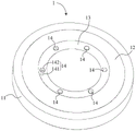
图1为本实用新型一实施例提供的电磁炉的俯视结构图;FIG. 1 is a top-view structural view of an induction cooker according to an embodiment of the present invention;
图2为图1对应的剖视图;Fig. 2 is a sectional view corresponding to Fig. 1;
图3为本实用新型一实施例提供的电磁炉上放置有锅具时的整体结构示意图;3 is a schematic diagram of the overall structure of the induction cooker provided by an embodiment of the present invention when a cooker is placed;
图4为本实用新型一实施例提供的电磁炉上放置有锅具时的整体结构剖视图;4 is a cross-sectional view of the overall structure of the induction cooker provided by an embodiment of the present invention when pots are placed;
图5为本实用新型另一实施例提供的电磁炉的俯视结构图。FIG. 5 is a top-view structural view of an induction cooker according to another embodiment of the present invention.
附图标记说明:Description of reference numbers:
1—电磁炉;1—Induction cooker;
11—底壳;11—bottom shell;
12—面板;12—Panel;
13—支撑台;13—support table;
131—支撑台段;131—support platform section;
14—测温装置;14—temperature measuring device;
141—测温探头;141—temperature probe;
142—感温金属壳;142—temperature sensing metal shell;
121—避让孔;121—avoidance hole;
2—锅具;2—pots;
21—锅底。21 - The bottom of the pot.
具体实施方式Detailed ways
为了更清楚地说明本实用新型实施例或现有技术中的技术方案,下面将对实施例或现有技术描述中所需要使用的附图作一简单地介绍,显而易见地,下面描述中的附图是本实用新型的一些实施例,对于本领域普通技术人员来讲,在不付出创造性劳动性的前提下,还可以根据这些附图获得其他的附图。In order to illustrate the embodiments of the present invention or the technical solutions in the prior art more clearly, the following briefly introduces the accompanying drawings used in the description of the embodiments or the prior art. Obviously, the accompanying drawings in the following description The drawings are some embodiments of the present invention. For those of ordinary skill in the art, other drawings can also be obtained from these drawings without creative labor.
实施例一Example 1
图1为本实用新型一实施例提供的电磁炉的俯视结构图;图2为图1对应的剖视图;图3为本实用新型一实施例提供的电磁炉上放置有锅具时的整体结构示意图;图4为本实用新型一实施例提供的电磁炉上放置有锅具时的整体结构剖视图。参照图1至图4所示,本实施例提供一种电磁炉1。1 is a top view of an induction cooker provided by an embodiment of the present utility model; FIG. 2 is a cross-sectional view corresponding to FIG. 1; 4 is a cross-sectional view of the overall structure of the induction cooker provided by an embodiment of the present invention when pots are placed on it. Referring to FIG. 1 to FIG. 4 , this embodiment provides an
该电磁炉1可包括:底壳11、线圈盘、控制板和面板12。其中,面板 12盖设在底壳11上,面板12可以是陶瓷面板,也可以是玻璃面板,本实用新型对面板12的材质不作限定。线圈盘和控制板位于底壳11和面板12围成的空间内。The
底壳11具体可包括:下盖以及位于下盖上的上盖,下盖具体可包括:底壁和围成在底壁外周的侧壁,即,下盖为腔体结构。上盖为框形盖,上盖盖设在下盖的上边缘,面板12盖设在上盖上。也就是说,面板12、上盖和下盖共同围成可放置线圈盘、控制板等部件的腔体。当然,在其他实现方式中,底壳11也可以为一个整体结构。线圈盘具体可包括:线圈盘架和位于线圈盘架上的线圈。线圈比如可以由漆包铜线或漆包铝线绕制而成。线圈盘与控制板电连接。The
为了使电磁炉1能够对放置在其上的锅具2进行控温,电磁炉1上还设有测温装置14。在现有技术中,测温装置具体设置在面板的下方,从而间接探测放置在面板上的锅具的温度。测温装置将温度传递至电磁炉的控制板,从而使电磁炉根据接收到的温度实现对锅具的控温。由于现有技术的测温装置设置在面板的下方,导致对锅具的温度测试不够准确,进而导致电磁炉对锅具的控温不够精确。In order to enable the
基于此,在本实施例中,面板12上设置有用于支撑锅具2的支撑台13,测温装置14设置在支撑台13中,且测温装置14的采温端显露在支撑台13 的顶部,以与锅具2的锅底21接触。Based on this, in this embodiment, the
也就是说,当锅具2放置在电磁炉1上时,锅具2通过支撑台13支撑在电磁炉1上,且测温装置14与锅具2的锅底21直接接触,即,通过测温装置14直接检测锅具2的锅底21的温度,从而提高了温度测试的准确性,为电磁炉1对锅具2的精确控温提供了保障。同时,由于锅具2通过支撑台13 支撑在电磁炉1上,即,锅具2与面板12不直接接触,从而可在一定程度上减小锅具2的热量向面板12的传递,进而在一定程度上避免锅具的热量向下传递至电磁炉1内的器件(比如线圈盘)而导致器件温升过高的情况出现,保证了电磁炉1的正常工作。That is to say, when the
此处需要说明的是,采温端显露在支撑台13的顶部可以理解为:采温端的顶端与支撑台13的上表面平齐,或者,采温端的顶端高于支撑台13的上表面,从而便于采温端与锅具2的锅底21接触。It should be noted here that the exposure of the temperature-collecting end on the top of the support table 13 can be understood as: the top of the temperature-collecting end is flush with the upper surface of the support table 13, or the top of the temperature-collecting end is higher than the upper surface of the support table 13, Therefore, it is convenient for the temperature collecting end to contact with the bottom 21 of the
利用电磁炉1进行烹饪时,将锅具2放置在面板12的支撑台13上,通过支撑台13将锅具2支撑在电磁炉1上,此时,支撑台13上的测温装置14 的采温端与锅底21直接接触。给电磁炉1通电,此时会有高频的电流通过线圈盘上的线圈,从而产生无数封闭的磁场力,磁力线切割锅具2,在锅具2 的锅底21产生无数小涡流,从而对锅具2进行加热。由于电磁炉1是通过线圈通电后产生的磁力线切割锅具2而对锅具2进行加热的,因此,可以理解的是,使用在电磁炉1上的锅具2是可导磁的。比如,锅具2可以是不锈钢锅具,也可以为铁锅等,本实用新型并不以此为限,只要是能够导磁且符合食品卫生安全的材质即可。When using the
加热过程中,测温装置14直接采集锅具2的锅底21的温度,测温装置 14将温度实时或者以一定频率传递至电磁炉1的控制板,从而使电磁炉1 根据接收到的温度实现对锅具2的精确控温,从而实现电磁炉1煲汤、煮粥、煎炸等功能。During the heating process, the
在本实施例中,控制板具体设置在底壳11内,测温装置14与底壳11内的控制板电连接。在其他实现方式中,也可以是,电磁炉1具有配套的遥控器,电磁炉1的控制板位于遥控器内,测温装置14与遥控器内的控制板通过无线的方式电连接,同样可实现温度信号的及时有效传输。In this embodiment, the control board is specifically arranged in the
参照图1至图4所示,在本实施例中,支撑台13具体包括至少两个支撑台段131,至少两个支撑台段131沿面板12的周向间隔排布。至少两个支撑台段131中,至少有一个支撑台段131中设置有至少一个测温装置14。也就是说,通过周向间隔排布的至少两个支撑台段131对锅具2进行支撑,不仅保证了对锅具2的有效支撑,且提高了电磁炉1的平衡性和外观美感。Referring to FIGS. 1 to 4 , in this embodiment, the support table 13 specifically includes at least two
进一步地,可将支撑台段131设置为至少三个,至少三个支撑台段131 以面板12的中心为圆心呈辐射状排布。这样可进一步提高对锅具2的支撑效果以及电磁炉1的外观美感。Further, at least three supporting
在本实施例中,面板12的形状具体为圆形,在其他实现方式中,面板12也可以为方形或者椭圆形等,本实用新型对面板12的形状不作限定。In this embodiment, the shape of the
示例性的,在本实施例中,支撑台段131具体为6个,6个支撑台段131 沿面板12的周向均匀排布。每个支撑台段131上分别设置一个测温装置14。对于支撑台段131的具体个数,本实用新型并不限于此。比如,支撑台段131 也可以为3个、4个、5个或者6个以上。Exemplarily, in this embodiment, there are six supporting
另外,需要说明的是,可以仅在其中一个支撑台段131上设置测温装置 14,也可以在每一个支撑台段131上均设置测温装置14。每一个支撑台段131 上的测温装置14可以是一个,也可以是多个。In addition, it should be noted that the
当测温装置14为至少两个时,通过至少两个测温装置14对锅底21 的不同位置进行测温,这样可进一步提高测温的准确性,而且若其中某个测温装置14意外损坏,可通过其他测温装置14进行测温,为电磁炉1对锅具2的控温提供了保障。When there are at least two
当支撑台段131中设置有测温装置14时,比如,一个支撑台段131上设置有一个测温装置14,较为优选的,可使该测温装置14位于支撑台段131 的靠近面板12中心的一端,这样使得测温装置14尽可能的检测锅底21中心的温度或者检测锅底21中心附近的温度,从而进一步提高对锅具2控温的精确性。当一个支撑台段131上设置多个测温装置14,可使其中一个测温装置 14位于支撑台段131的靠近面板12中心的一端。When the
至少两个支撑台段131也可以沿面板12的周向排布呈环形,此时,可使至少一个支撑台段131上设置至少一个测温装置14,在该种情况下,具体可以使支撑台段131上的至少一个测温装置14设置在支撑台段131的靠近面板 12中心的位置。The at least two
在本实施例中,支撑台13通过螺钉固定在面板12上。具体地,面板12 上开设有螺孔,支撑台13的对应面板12的螺孔的位置也具有螺孔,支撑台 13通过穿设在两个相对的螺孔中的螺钉固定在面板12上。其中,支撑台13 的螺孔可以由支撑台13的底面向上延伸至支撑台13内,这样可以不仅能够保证支撑台13的有效固定,而且可保证支撑台13顶面的完整性,提高电磁炉1的外观美感,同时还可以防止水从支撑台顶面进入至底壳11内。In this embodiment, the support table 13 is fixed on the
在其他实现方式中,支撑台13也可以粘接在面板12上,比如,支撑台 13通过耐高温的硅酮胶粘接在面板12上。或者,支撑台13卡设在面板12 上,比如,面板12上具有卡槽,支撑台13上具有可与卡槽匹配卡合的卡凸。In other implementation manners, the support table 13 can also be bonded to the
如果将支撑台13的高度设置的过高,不仅会导致耗材的浪费,而且会导致放置在支撑台13上方的锅具2与电磁炉1内的线圈盘之间的距离较远,无法保证线圈盘通电产生的磁力线能够有效的切割到锅具2的锅底21,即,无法保证对锅具2的正常加热。但若将支撑台13的高度设置的过低,则会导致放置在支撑台13上的锅具2与面板12之间的距离太近,而导致锅具2向下辐射至面板12的热量较多,热量会传递至线圈盘而导致线圈盘温升过高而发生损坏,影响电磁炉1的正常使用。基于此,在本实施例中,可将支撑台13 的高度设置在1mm~5mm之间,不仅保证了锅具2与线圈盘之间的距离,使线圈盘通电产生的磁力线能够有效切割到锅具2的锅底21,进而为锅具2进行加热,同时,还可避免锅底21与面板12之间的距离太近而导致锅具2的热量向下辐射给面板12,进而传递至线圈盘而导致线圈盘温升过大的情况出现。If the height of the support table 13 is set too high, not only will consumables be wasted, but also the distance between the
由于一些锅具2的底面是平面,一些锅具2的底面是上凹的凹面,一些锅具2的锅底不平整,因此为了进一步保证测温装置14测温的准确性以及该电磁炉1的适用范围,在本实施例中,具体可使测温装置14的采温端的顶面高于支撑台13的上表面,从而可以保证当锅具2放置在支撑台13上,测温装置14的采温端能够与锅底21抵接。这样使得不仅平底锅可以在该电磁炉 1上使用,锅底不平的锅具也可以在该电磁炉1上使用。Since the bottom surfaces of some
继续参照图1至图4,在本实施例中,测温装置14具体可包括测温探头 141以及套设在测温探头141的采温端的感温金属壳142。其中,感温金属壳 142的至少部分显露在支撑台13的顶部,以与锅具2的锅底21接触。此处感温金属壳142的至少部分显露在支撑台13的顶部可以理解为:感温金属壳 142的顶面与支撑台13的上表面平齐,或者,感温金属壳142的顶面高于支撑台13的上表面。将锅具2放置在电磁炉1上时,此时感温金属壳142直接接触锅具2的锅底21,通过感温金属壳142将锅具2的热量快速传递到测温探头141,测温探头141将检测到的温度传递至电磁炉1的控制板,通过控制板实现对锅具2的精确控温,测温装置14结构简单且使用安全。1 to 4, in this embodiment, the
在本实施例中,感温金属壳142具体为铝质壳体,从而使得传热更加快速更加有效,为准确测温提供了保障。当然,感温金属壳142也可以为铜质等其他传热性能好的材质。In this embodiment, the temperature-sensing
具体实现时,面板12的对应测温装置14的位置开设有避让孔121,测温探头141的连接端从该避让孔121穿出,以与电磁炉1的控制板电连接。具体地,测温探头141的连接端可以通过引线与控制板电连接,这样可进一步保证信号传递的可靠性。在其他实现方式中,也可以是,测温探头141位于支撑台13中,无需在面板12上开设避让孔121,测温探头141的连接端与控制板之间通过无线的方式电连接。In specific implementation, an
在本实施例中,支撑台13具体为塑胶支撑台。通过将支撑台13设置为塑胶支撑台,不仅成本低,且对锅具2而言起到了一定的防滑作用,在一定程度上防止溜锅的情况出现,提高了加热效果以及使用安全性。In this embodiment, the support table 13 is specifically a plastic support table. By setting the
此外,还可以在支撑台13的与锅具2接触的面上设置防滑结构,比如,将支撑台13的上表面设置为磨砂面,该磨砂面形成为上述的防滑结构,或者,防滑结构为在制作支撑台13时,在支撑台13的上表面添加的防滑颗粒,或者防滑结构为防滑条纹、防滑凸起等。通过设置防滑结构,增大了锅具2与支撑台13之间的摩擦力,可使锅具2能够稳定的放置在支撑台13上,使锅具2不会轻易晃动或者移动,有效防止溜锅现象出现,提高了加热效果以及使用安全性。In addition, a non-slip structure can also be provided on the surface of the support table 13 that is in contact with the
在一种可行的实现方式中,当支撑台13为塑胶支撑台时,可以将感温金属壳142注塑在支撑台13中。这样不仅提高了测温装置14与支撑台13这个整体结构的稳定性,为测温装置14的准确测温提供了保障,而且制作简单,安装可靠。另外,由于两者一体注塑,即使面板12上有水,水也不会接触到测温探头141,对测温装置14进行了有效保护。当然,支撑台13也可以为其他材质,比如陶瓷材质,或者为其他不导热且强度较高的材质。In a feasible implementation manner, when the support table 13 is a plastic support table, the temperature-sensing
在另一种可行的实现方式中,支撑台13的对应测温装置14的位置开设有通孔,感温金属壳142的至少部分穿设在通孔中,且感温金属壳142与通孔的孔壁之间密封设置。这样不仅保证了测温装置14与锅底的有效接触,而且可防止面板12上的水或者锅具2外溢上的水从感温金属壳142与通孔之间的接合处流下而导致测温探头141损坏的情况出现。In another feasible implementation manner, a through hole is formed on the support table 13 at a position corresponding to the
实施例二
图5为本实用新型另一实施例提供的电磁炉的俯视结构图。参照图5所示,本实施例提供另一种结构的电磁炉。本实施例的电磁炉1与实施例一的区别在于:支撑台13的具体形状不同。FIG. 5 is a top-view structural view of an induction cooker according to another embodiment of the present invention. Referring to FIG. 5 , this embodiment provides an induction cooker with another structure. The difference between the
在本实施例中,支撑台13具体为环形支撑台。这样可从锅底21的整个周向上对锅具进行支撑,使得锅具2更加稳定,且支撑台13的结构简单、易制作。In this embodiment, the support table 13 is specifically an annular support table. In this way, the cookware can be supported from the entire circumference of the
其中,可在支撑台13上设置至少两个测温装置14,至少两个测温装置 14沿支撑台13的周向间隔排布。较为优选的,至少两个测温装置14沿支撑台13的周向均布。通过至少两个测温装置14分别对锅具2的不同位置进行测温,进一步提高了测温的精确性;而且若其中某个测温装置14意外损坏,可通过其他测温装置14进行测温,为电磁炉1对锅具2的控温提供了保障。Wherein, at least two
当然,在其他实现方式中,环形支撑台上也可以仅设置一个测温装置14。Of course, in other implementation manners, only one
较为优选的,可以将测温装置14设置在环形支撑台的靠近面板12中心的位置,这样使得测温装置14尽可能的检测锅底21中心附近的温度,进一步提高测温的精确性。Preferably, the
无论支撑台13设置为实施例一所示的至少两个支撑台段,还是设置为实施例二所示的环形支撑台,均可以使支撑台13中的至少一个测温装置14设置在支撑台13的靠近面板12中心的位置,以进一步提高测温的准确性。Regardless of whether the support table 13 is configured as at least two support table sections shown in the first embodiment, or as the annular support table shown in the second embodiment, at least one
其他技术特征与实施例一相同,并能达到相同或者类似的技术效果,在此不再一一赘述。Other technical features are the same as those in the first embodiment, and can achieve the same or similar technical effects, which will not be repeated here.
最后应说明的是:以上各实施例仅用以说明本实用新型的技术方案,而非对其限制;尽管参照前述各实施例对本实用新型进行了详细的说明,本领域的普通技术人员应当理解:其依然可以对前述各实施例所记载的技术方案进行修改,或者对其中部分或者全部技术特征进行等同替换;而这些修改或者替换,并不使相应技术方案的本质脱离本实用新型各实施例技术方案的范围。Finally, it should be noted that the above embodiments are only used to illustrate the technical solutions of the present utility model, but not to limit them; although the present utility model has been described in detail with reference to the foregoing embodiments, those of ordinary skill in the art should understand that : it can still modify the technical solutions recorded in the foregoing embodiments, or perform equivalent replacements to some or all of the technical features; and these modifications or replacements do not make the essence of the corresponding technical solutions deviate from the various embodiments of the present utility model Scope of technical solutions.
Claims (11)
Priority Applications (1)
| Application Number | Priority Date | Filing Date | Title |
|---|---|---|---|
| CN201921912212.1U CN210891796U (en) | 2019-11-07 | 2019-11-07 | induction cooker |
Applications Claiming Priority (1)
| Application Number | Priority Date | Filing Date | Title |
|---|---|---|---|
| CN201921912212.1U CN210891796U (en) | 2019-11-07 | 2019-11-07 | induction cooker |
Publications (1)
| Publication Number | Publication Date |
|---|---|
| CN210891796U true CN210891796U (en) | 2020-06-30 |
Family
ID=71340655
Family Applications (1)
| Application Number | Title | Priority Date | Filing Date |
|---|---|---|---|
| CN201921912212.1U Expired - Fee Related CN210891796U (en) | 2019-11-07 | 2019-11-07 | induction cooker |
Country Status (1)
| Country | Link |
|---|---|
| CN (1) | CN210891796U (en) |
-
2019
- 2019-11-07 CN CN201921912212.1U patent/CN210891796U/en not_active Expired - Fee Related
Similar Documents
| Publication | Publication Date | Title |
|---|---|---|
| KR101568562B1 (en) | Electronic module for temperature-monitored preparation of food in a cooking vessel | |
| WO2010091557A1 (en) | Electromagnetic oven for barbecue | |
| AU2015316751B2 (en) | Induction cooking pan with temperature measurement | |
| CN103796558A (en) | Induction heating device for heating a liquid | |
| KR101429655B1 (en) | induction range | |
| CN107912978A (en) | A kind of intelligent electromagnetic heating kettle | |
| US10827565B2 (en) | Induction cooktop system with a temperature sensor | |
| CN111685586B (en) | A pot identification method, structure and cooking device with pot identification function | |
| CN206166684U (en) | Temperature measuring device and cooking utensil | |
| CN210891796U (en) | induction cooker | |
| JP6663609B2 (en) | Electromagnetic induction heating equipment | |
| JP6223481B2 (en) | Cooking device and temperature detector | |
| CN205994262U (en) | Cooking apparatus | |
| CN209995914U (en) | Pots and Induction Cookware | |
| CN210018909U (en) | Pots and Induction Cookware | |
| CN207754983U (en) | Ceramic pan and electromagnetism furnace module | |
| CN207555664U (en) | Cooking device | |
| CN209694859U (en) | A cooking utensil that can detect the degree of cooking of ingredients | |
| CN210300603U (en) | cooker | |
| CN210373583U (en) | Electromagnetic oven | |
| CN100595488C (en) | Electric heating cooker for accurate temperature measurement and method for accurate temperature measurement of electric heating cooker | |
| CN209235709U (en) | Induction Pots and Induction Cookware | |
| CN206959028U (en) | Electromagnetic oven | |
| CN208755703U (en) | A kind of intelligent electromagnetic heating kettle | |
| CN212346202U (en) | Pan discernment structure and have cooking ware of pan recognition function |
Legal Events
| Date | Code | Title | Description |
|---|---|---|---|
| GR01 | Patent grant | ||
| GR01 | Patent grant | ||
| CF01 | Termination of patent right due to non-payment of annual fee | ||
| CF01 | Termination of patent right due to non-payment of annual fee |
Granted publication date: 20200630 |