CN210972768U - Automatic sand paving device on hydraulic engineering inclined plane - Google Patents
Automatic sand paving device on hydraulic engineering inclined plane Download PDFInfo
- Publication number
- CN210972768U CN210972768U CN201921957495.1U CN201921957495U CN210972768U CN 210972768 U CN210972768 U CN 210972768U CN 201921957495 U CN201921957495 U CN 201921957495U CN 210972768 U CN210972768 U CN 210972768U
- Authority
- CN
- China
- Prior art keywords
- sanding
- track
- door
- leg
- sand
- Prior art date
- Legal status (The legal status is an assumption and is not a legal conclusion. Google has not performed a legal analysis and makes no representation as to the accuracy of the status listed.)
- Active
Links
- 239000004576 sand Substances 0.000 title claims abstract description 132
- 239000000463 material Substances 0.000 claims abstract description 84
- 230000007480 spreading Effects 0.000 claims abstract description 18
- 238000003892 spreading Methods 0.000 claims abstract description 18
- 238000007599 discharging Methods 0.000 claims abstract description 16
- 238000004804 winding Methods 0.000 claims description 69
- 210000004907 gland Anatomy 0.000 claims description 29
- 229910000831 Steel Inorganic materials 0.000 claims description 7
- 238000000926 separation method Methods 0.000 claims description 7
- 239000010959 steel Substances 0.000 claims description 7
- 238000009826 distribution Methods 0.000 claims description 4
- 230000000149 penetrating effect Effects 0.000 claims description 3
- 230000032258 transport Effects 0.000 description 81
- 238000010586 diagram Methods 0.000 description 12
- 238000010276 construction Methods 0.000 description 6
- 238000000034 method Methods 0.000 description 4
- XLYOFNOQVPJJNP-UHFFFAOYSA-N water Substances O XLYOFNOQVPJJNP-UHFFFAOYSA-N 0.000 description 4
- 230000009471 action Effects 0.000 description 3
- 235000019994 cava Nutrition 0.000 description 3
- 230000005484 gravity Effects 0.000 description 3
- 238000002955 isolation Methods 0.000 description 3
- 238000005096 rolling process Methods 0.000 description 3
- 238000005520 cutting process Methods 0.000 description 2
- 238000011161 development Methods 0.000 description 2
- 239000010410 layer Substances 0.000 description 2
- 239000000203 mixture Substances 0.000 description 2
- 230000004048 modification Effects 0.000 description 2
- 238000012986 modification Methods 0.000 description 2
- 230000008569 process Effects 0.000 description 2
- 239000000725 suspension Substances 0.000 description 2
- 230000009286 beneficial effect Effects 0.000 description 1
- 238000013461 design Methods 0.000 description 1
- 230000000694 effects Effects 0.000 description 1
- 238000005516 engineering process Methods 0.000 description 1
- 230000002349 favourable effect Effects 0.000 description 1
- 230000006872 improvement Effects 0.000 description 1
- 238000009434 installation Methods 0.000 description 1
- 230000003137 locomotive effect Effects 0.000 description 1
- 238000003825 pressing Methods 0.000 description 1
- 230000002265 prevention Effects 0.000 description 1
- 239000011241 protective layer Substances 0.000 description 1
- 238000013519 translation Methods 0.000 description 1
- 238000003466 welding Methods 0.000 description 1
Images


Landscapes
- Road Paving Machines (AREA)
Abstract
The utility model discloses an automatic device of sanding on hydraulic engineering inclined plane, include: the sanding track is obliquely arranged; the door-shaped upper leg supporting device is arranged at the upper end of the sanding track and is connected with the sanding track, and a winch is arranged on the door-shaped upper leg supporting device; the door-shaped lower supporting leg device is arranged at the lower end of the sanding track and is connected with the sanding track; the sand material transport vehicle is arranged on the sand paving track in a sliding mode, the winch is detachably connected with the sand material transport vehicle through the pull rope, and the sand material transport vehicle is provided with an automatic discharging device; the spiral spreading machine is arranged on the sand paving track in a sliding mode, and the winch is detachably connected with the spiral spreading machine through the pull rope. This automatic device of sanding on hydraulic engineering inclined plane can reduce artifical intensity of labour effectively, improve sanding efficiency, guarantee that the sanding thickness is even to can not lead to the fact the damage to the geomembrane that has laid.
Description
Technical Field
The utility model relates to a hydraulic engineering technical field particularly, relates to an automatic device of spreading sand on hydraulic engineering inclined plane.
Background
The method solves the problem of uneven space-time distribution of water resources in order to meet the requirement of rapid development of the economic society, and the water requirements of various regions are increasingly large, so that the utilization rate of the water resources is urgently improved. Engineering water shortage in most areas of Yunnan has become a main factor severely restricting local development, most mountainous areas are karst landforms, karst is developed and is often seen in karst caves, underground rivers and the like, and the existing domestic exploration technology is difficult to completely detect specific leakage positions in all karst caves and underground rivers, so that the leakage phenomenon is caused when the karst caves and the underground rivers are built.
The most common reservoir seepage treatment solution is the laying of geomembranes. Before and after the geomembrane is laid, sand needs to be laid as a cushion layer, a reverse filter layer or a protective layer. The traditional construction method for spreading sand on the geomembrane is to manually pull and spread sand materials, so that the method has the advantages of manpower and material resource consumption, low efficiency, incapability of ensuring uniform sand spreading thickness, easiness in artificial damage to the spread geomembrane and failure of the geomembrane seepage prevention scheme.
SUMMERY OF THE UTILITY MODEL
A primary object of the utility model is to provide an automatic device of spreading sand on hydraulic engineering inclined plane, this automatic device of spreading sand can reduce artifical intensity of labour, improve the efficiency of spreading sand, guarantee that the thickness of spreading sand is even to can not cause the damage to the geomembrane of having laid.
In order to realize the above-mentioned purpose, the utility model provides an automatic device of spreading sand on hydraulic engineering inclined plane, include:
the sanding track is obliquely arranged;
the door-shaped upper leg supporting device is arranged at the upper end of the sanding track and is connected with the sanding track, and a winch is arranged on the door-shaped upper leg supporting device;
the door-shaped lower supporting leg device is arranged at the lower end of the sanding track and is connected with the sanding track;
the sand material transport vehicle is arranged on the sand paving track in a sliding mode, the winch is detachably connected with the sand material transport vehicle through the pull rope, and the sand material transport vehicle is provided with an automatic discharging device;
the spiral spreading machine is arranged on the sand paving track in a sliding mode, and the winch is detachably connected with the spiral spreading machine through the pull rope.
Further, sand material transport vechicle includes:
the transport vehicle chassis is arranged on the sand paving track in a sliding manner through transport lane wheels;
the rear end of the car pocket is hinged with the rear end of the transport vehicle chassis, the rear end of the car pocket is provided with a car pocket door, and the upper end of the car pocket door is hinged with the upper side of the rear end of the car pocket;
the automatic discharging device is used for turning up the bicycle bag at the rear end and simultaneously opening the bicycle bag door for discharging.
Further, the automatic discharging device includes:
the hydraulic push rod for lifting the car bag is arranged at the front end of the car bag, one end of the hydraulic push rod for lifting the car bag is hinged to the chassis of the transport vehicle, and the other end of the hydraulic push rod for lifting the car bag is hinged to the car bag;
one end of the connecting rod is hinged to a chassis of the transport vehicle, the other end of the connecting rod is hinged to a rotating arm, and the other end of the rotating arm is fixedly connected to a hinged shaft for hinging a car pocket door and a car pocket; the connecting rod and the rotating arm are used for opening the car pocket door when the car pocket lifts the hydraulic push rod to lift the car pocket, and closing the car pocket door when the car pocket lifts the hydraulic push rod to put down the car pocket.
Furthermore, be equipped with the polylith in the bicycle bag and divide the material baffle, divide the material baffle to set up to the outside slope gradually by the front end to the rear end of bicycle bag, and the polylith divides the material baffle along the length direction central line symmetrical arrangement of bicycle bag.
Further, the side plates of the bicycle bag are gradually heightened from the front end to the rear end of the bicycle bag.
Furthermore, a supporting wheel device is arranged below the chassis of the transport vehicle, and a brake device and a rail clamping device are further arranged on the chassis of the transport vehicle.
Furthermore, the sanding track comprises a first track and a second track, the second track is located below the first track, and the first track and the second track are connected through a truss structure.
Furthermore, a hopper is arranged above the sanding track on the door-shaped upper supporting leg device, and an electric single-beam suspension travelling crane is arranged above the hopper.
Further, the spiral spreader includes:
the flattening machine body is arranged on the sanding track in a sliding manner through flattening machine road wheels;
the spiral spreading shaft is arranged on the spiral shaft mounting rack;
and the hydraulic telescopic arms are arranged at the front end and the rear end of the flattening machine body, and piston rods of the hydraulic telescopic arms are connected with the screw shaft mounting rack.
Furthermore, the upper end of the sanding track is connected with the door type upper supporting leg device through a universal joint spherical shaft head, and the lower end of the sanding track is connected with the door type lower supporting leg device through a universal joint.
Furthermore, a plurality of track brackets are arranged on the sanding track, the top of the door-shaped upper supporting leg device is connected with the track brackets through an inclined steel cable, and the top of the door-shaped lower supporting leg device is connected with the track brackets through an inclined steel cable.
Furthermore, landing leg device under landing leg device and the door type all includes a door type landing leg support body on the door type, and door type landing leg support body passes through bolted connection by many connecting rods and constitutes.
Further, the bottom of door type landing leg support body is equipped with landing leg altitude mixture control structure, and landing leg altitude mixture control structure includes:
the lifting nut is fixedly arranged at the bottom of the door-shaped landing leg frame body;
the lifting screw rod is arranged in the lifting nut in a penetrating mode, the lifting screw rod is in threaded connection with the lifting nut, and a universal joint spherical head is arranged at the lower end of the lifting screw rod;
the ball head seat is provided with a hemispherical groove, and the universal joint ball head is arranged in the hemispherical groove;
the ball seat gland is installed on the ball seat through bolt connection, a gland groove is formed in the ball seat gland, and the ball joint ball head is buckled in the hemispherical groove and the gland groove through the ball seat gland.
Further, the bottom of door type landing leg support body is equipped with landing leg moving structure, and landing leg moving structure includes:
the moving structure ball head seat is arranged at the bottom of the door-shaped supporting leg frame body through a passage wheel shaft, and a passage wheel ball head groove is formed in the bottom of the moving structure ball head seat;
the moving structure ball head support is provided with a moving structure universal joint ball head;
the moving structure ball head gland is installed below the moving structure ball head seat through bolt connection, and the moving structure universal joint ball head is buckled in the road wheel ball head groove;
and the walking roller is rotatably arranged on the moving structure ball head bracket.
Furthermore, two walking rollers are arranged on the ball head support of the moving structure in parallel.
Further, the hoist includes:
the stand is arranged on the door-shaped upper support leg device;
the winding drum is rotatably arranged on the base, and a pull rope is wound on the winding drum;
and the winding motor is arranged on the base, an output shaft of the winding motor is connected with the winding drum, and the winding motor is used for driving the winding drum to rotate.
Furthermore, the winding drum comprises a first winding drum and a second winding drum, a first balance pulley is arranged on the machine base corresponding to the first winding drum, a second balance pulley is arranged on the machine base corresponding to the second winding drum, the first winding drum and the second winding drum are respectively provided with an isolation tooth, the first winding drum is divided into a first rope winding area and a second rope winding area by the isolation tooth, the second winding drum is divided into a third rope winding area and a fourth rope winding area by the isolation tooth, a first transport vehicle pulley, a second transport vehicle pulley, a third transport vehicle pulley and a fourth transport vehicle pulley are arranged at the front end of the sand transport vehicle side by side, a pull rope on the first rope winding area sequentially winds around the first transport vehicle pulley, the first balance pulley and the second transport vehicle pulley are connected into a second rope rolling area, and the pull rope in the third rope rolling area is connected into a fourth rope rolling area after sequentially passing around the third transport vehicle pulley, the second balance pulley and the fourth transport vehicle pulley.
Compared with the prior art, the utility model discloses following beneficial effect has:
the utility model discloses an automatic sanding device, through set up door type upper leg device, door type lower leg device respectively at the upper and lower both ends of the hydraulic engineering inclined plane of waiting to sand, will sand paving the track and connect between door type upper leg device and door type lower leg device, slide sand material transport vechicle and spiral stand flat-bed machine and set up on sand paving the track, and draw sand material transport vechicle and spiral stand flat-bed machine to slide along sand paving the track through the hoist engine; when the sand material transport vehicle moves upwards along the sand paving track, the automatic discharging device opens the sand material transport vehicle to pave sand. This automatic device of sanding can reduce the artifical intensity of labour of sanding operation effectively, improve sanding efficiency, guarantee that the sanding thickness is even to, when sanding on the geomembrane that has laid, can not cause the damage to the geomembrane.
The present invention will be described in further detail below with reference to the accompanying drawings.
Drawings
The accompanying drawings, which form a part of the present application, are included to provide a further understanding of the invention, and are incorporated in and constitute a part of this specification, illustrate embodiments of the invention and together with the description serve to explain the invention and not to limit the invention. In the drawings:
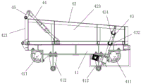
fig. 1 is the overall structure schematic diagram of the automatic sanding device of the embodiment of the utility model.
Fig. 2 is the utility model discloses the structure schematic diagram of sand material transport vechicle in automatic sanding device.
Fig. 3 is the utility model discloses sand material transport vechicle overlook the schematic structure diagram in automatic sanding device.
Fig. 4 is the utility model discloses the overlook structure schematic diagram of chassis among the automatic sanding device.
Fig. 5 is the structure diagram of the car bag in the automatic sanding device of the embodiment of the utility model.
Fig. 6 is the utility model discloses the orbital structure schematic diagram of shop sand in the automatic sanding device of embodiment.
Fig. 7 is a schematic structural view of a spiral spreader-leveler in the automatic sanding device of the embodiment of the present invention.
Fig. 8 is a schematic structural view of a spiral leveling shaft in the automatic sanding device according to the embodiment of the present invention.
Fig. 9 is a schematic structural view of a supporting leg height adjusting structure in the automatic sanding device according to the embodiment of the present invention.
Fig. 10 is an internal structure diagram of a leg height adjusting structure in the automatic sanding device according to an embodiment of the present invention.
Fig. 11 is a schematic structural view of a ball seat in the automatic sanding device according to the embodiment of the present invention.
Fig. 12 is a schematic top view of the ball seat gland of the automatic sanding device according to the embodiment of the present invention.
Fig. 13 is a schematic view of a cross-sectional structure of the ball seat gland in the automatic sanding device according to the embodiment of the present invention.
Fig. 14 is a schematic structural diagram of a lifting nut in the automatic sanding device according to the embodiment of the present invention.
Fig. 15 is the utility model discloses a lifting nut's among automatic sanding device sectional structure schematic diagram.
Fig. 16 is a schematic cross-sectional structural view of a supporting leg moving structure in the automatic sanding device according to an embodiment of the present invention.
Fig. 17 is a schematic side view of a supporting leg moving structure in the automatic sanding device according to the embodiment of the present invention.
Fig. 18 is a schematic structural view of the supporting leg moving structure in the automatic sanding device according to the embodiment of the present invention after the moving structure ball seat and the moving structure ball gland are removed.
Fig. 19 is a schematic view of a sectional structure of the moving structure ball head seat and the moving structure ball head gland in the automatic sanding device according to the embodiment of the present invention.
Fig. 20 is a schematic cross-sectional structural view of a ball cup with a moving structure in an automatic sanding device according to an embodiment of the present invention.
Fig. 21 is a schematic cross-sectional view of the ball cup with the moving structure in the automatic sanding device according to the embodiment of the present invention along another direction.
Fig. 22 is a schematic structural view of the ball head gland with the moving structure in the automatic sanding device of the embodiment of the present invention.
Fig. 23 is a schematic view of a sectional structure of the ball head gland with a moving structure in the automatic sanding device of the embodiment of the present invention.
Fig. 24 is a schematic structural diagram of a winch in the automatic sanding device according to the embodiment of the present invention.
Fig. 25 is a schematic top view of a winch in the automatic sanding device according to the embodiment of the present invention.
Fig. 26 is a left side view of the structure of fig. 24.
Fig. 27 is a schematic view of a winding manner of a winch rope in the automatic sanding device according to the embodiment of the present invention.
Fig. 28 is a schematic top view of a frame in an automatic sanding device according to an embodiment of the present invention.
Fig. 29 is a schematic structural view of a door-shaped lower leg device in an automatic sanding device according to an embodiment of the present invention.
Fig. 30 is a schematic structural view of a supporting leg device on a door type in an automatic sanding device according to the embodiment of the present invention.
Fig. 31 is a schematic structural diagram of the other side of the upper supporting leg device of the door type in the automatic sanding device of the embodiment of the present invention.
Fig. 32 is a schematic diagram of a structure of a hydraulic push rod and a limiting device lifted by a car bag in the automatic sanding device according to the embodiment of the present invention.
Wherein the figures include the following reference numerals:
10. paving a sand track; 11. a first track; 12. a second track; 13. a truss structure; 14. a rail bracket; 20. a gate style upper leg unit; 30. a gate-type lower leg device; 40. a sand material transport vehicle; 41. a chassis of the transport vehicle; 42. a vehicle bag; 43. lifting a hydraulic push rod by the bicycle bag; 44. a connecting rod; 45. a rotating arm; 46. a first transporter pulley; 47. a second transporter pulley; 48. a third vehicle sheave; 49. a fourth vehicle sheave; 50. a spiral flattening machine; 51. flattening the locomotive body; 52. a screw shaft mounting rack; 53. a hydraulic telescopic arm; 60. a winch; 61. a machine base; 62. a reel; 63. a hoisting motor; 70. a hopper; 80. an electric single-beam suspension crane; 90. a diagonal steel cable; 100. a gate-type leg frame body; 110. a leg height adjusting structure; 111. lifting the nut; 112. lifting the screw rod; 113. a ball cup seat; 114. a ball seat gland; 120. a leg moving structure; 121. a moving structure ball head seat; 122. a moving structure ball head bracket; 123. a moving structure ball head gland; 124. a walking roller; 130. a material transportation road; 411. a transport lane wheel; 412. a riding wheel device; 421. a bag door; 422. a material distributing guide plate; 423. a side plate; 431. a retraction limiting device; 432. lifting a limiting device; 433. a limiting device fixing frame; 434. a movable rod; 435. a limiting cone; 511. flattening the road wheel of the machine; 512. flattening the riding wheels of the vehicle; 521. spirally flattening the shaft; 611. a first balance pulley; 612. a second balance pulley; 621. a first reel; 622. a second reel; 623. isolating teeth; 624. a first spooling zone; 625. a second spooling zone; 626. a third rope winding area; 627. a fourth rope winding area; 1121. a universal joint ball head; 1131. a hemispherical recess; 1141. pressing a cover groove; 1211. a road wheel ball head groove; 1221. and moving the structural universal joint ball head.
Detailed Description
To facilitate understanding of the present invention, the present invention will be described more fully and specifically with reference to the accompanying drawings and preferred embodiments, but the scope of the present invention is not limited to the specific embodiments described below. It should be noted that, in the present invention, the embodiments and features of the embodiments may be combined with each other without conflict.
Unless otherwise defined, all terms of art used hereinafter have the same meaning as commonly understood by one of ordinary skill in the art. The use of "first," "second," and similar terms in the description and in the claims does not indicate any order, quantity, or importance, but rather the intention is merely to facilitate a distinction between corresponding parts. Also, the use of the terms "a" or "an" and the like do not denote a limitation of quantity, but rather denote the presence of at least one. The terms "connected" or "coupled" and the like are not restricted to physical or mechanical connections, but may include electrical connections, whether direct or indirect. "upper", "lower", "left", "right", and the like are used merely to indicate relative positional relationships, and when the absolute position of the object being described is changed, the relative positional relationships are changed accordingly.
Referring to fig. 1 to 32, an automatic sanding device for hydraulic engineering inclined plane according to the embodiment of the present invention mainly includes a sanding track 10, a gate-type upper leg device 20, a gate-type lower leg device 30, a sand material transporting vehicle 40 and a spiral spreader 50. Wherein, the sand paving track 10 is obliquely arranged along the inclined plane of the hydraulic engineering to be paved with sand; the gate-type upper leg supporting device 20 is arranged on the upper side of the hydraulic engineering inclined plane to be sanded and is connected with the upper end of the sanding track 10, and a winch 60 is further arranged on the gate-type upper leg supporting device 20; the gate-shaped lower supporting leg device 30 is arranged on the lower side of the hydraulic engineering inclined plane to be sanded and is connected with the lower end of the sanding track 10; the sand material transport vehicle 40 is arranged on the sanding track 10 in a sliding mode, the winch 60 is detachably connected with the sand material transport vehicle 40 through a pull rope, the sand material transport vehicle 40 is pulled to slide on the sanding track 10 through the winch 60, the sand material transport vehicle 40 is further provided with an automatic discharging device, and when the sand material transport vehicle 40 moves upwards along the sanding track 10, the automatic discharging device opens the sand material transport vehicle 40 for sanding; the spiral spreader 50 is slidably disposed on the sanding track 10, the winch 60 is detachably connected to the spiral spreader 50 through a pull rope, and the spiral spreader 50 is pulled to slide on the sanding track 10 by the winch 60.
The automatic sanding device comprises a door-shaped upper supporting leg device 20 and a door-shaped lower supporting leg device 30 which are respectively arranged at the upper end and the lower end of a hydraulic engineering inclined plane to be sanded, a sanding track 10 is connected between the door-shaped upper supporting leg device 20 and the door-shaped lower supporting leg device 30, a sand material transport vehicle 40 and a spiral paver 50 are arranged on the sanding track 10 in a sliding mode, the sand material transport vehicle 40 and the spiral paver 50 are pulled to slide along the sanding track 10 through a winch 60, and when the sand material transport vehicle 40 moves upwards along the sanding track 10, the automatic discharging device opens the sand material transport vehicle 40 to perform sanding. This automatic device of sanding can reduce the artifical intensity of labour of sanding operation effectively, improve sanding efficiency, guarantee that the sanding thickness is even to, when sanding on the geomembrane that has laid, can not cause the damage to the geomembrane.
Specifically, referring to fig. 2 to 5, in the present embodiment, the sand transporter 40 includes a transporter chassis 41 and a bag 42, a plurality of transporter lane wheels 411 are provided on a lower side of the transporter chassis 41, and the transporter chassis 41 is slidably disposed on the sanding rail 10 by the transporter lane wheels 411; the bicycle bag 42 is arranged above the transport vehicle chassis 41, the rear end (namely the left end in fig. 2) of the bicycle bag 42 is hinged with the rear end of the transport vehicle chassis 41, a bicycle bag door 421 is arranged at the rear end of the bicycle bag 42, and the upper end of the bicycle bag door 421 is hinged with the upper side of the rear end of the bicycle bag 42; the automatic discharging device is installed on the carrier chassis 41 and the bag 42, and turns up the bag 42 toward the rear end when the sand carrier 40 moves upward along the sanding rail 10, and simultaneously opens the bag door 421 to discharge.
Referring to fig. 2, in the present embodiment, the automatic discharging device includes a bag lifting hydraulic push rod 43, a link 44, and a swing arm 45. Wherein, the bag lifting hydraulic push rod 43 is arranged at the front end of the bag 42, one end of the bag lifting hydraulic push rod 43 is hinged on the chassis 41 of the transport vehicle, and the other end is hinged on the bag 42; one end of the connecting rod 44 is hinged on the transport vehicle chassis 41, the other end of the connecting rod 44 is hinged with the rotating arm 45, and the other end of the rotating arm 45 is fixedly connected on a hinged shaft of the car pocket door 421 and the car pocket 42. Thus, through the reasonable arrangement of the length and the installation position of the connecting rod 44 and the rotating arm 45, when the car pocket lifting hydraulic push rod 43 extends out, the front end of the car pocket 42 is pushed to turn backwards, the car pocket 42 rotates around the hinge shaft of the car pocket and the transport vehicle chassis 41, meanwhile, the car pocket door 421 is pulled through the connecting rod 44 and the rotating arm 45 to rotate around the hinge shaft of the car pocket 42 on the upper side of the rear end, and therefore the car pocket door 421 is opened to unload materials. The car pocket lifting hydraulic push rod 43 can be controlled to ascend according to the sand laying thickness required by design, so that the inclination of the car pocket 42 is adjusted, the height of the car pocket door 421 is controlled, and the dumping amount of sand in unit time is adjusted.
In order to enable the sand to be poured on the surface to be paved more uniformly, referring to fig. 3, in the present embodiment, a plurality of distributing guide plates 422 are provided in the pockets 42, the distributing guide plates 422 are gradually inclined outward from the front ends to the rear ends of the pockets 42, and the distributing guide plates 422 are symmetrically arranged along the center line of the length direction of the pockets 42, and the distributing guide plates 422 integrally form a plurality of 'splayed' structures. The inner space of the bicycle bag 42 is divided into a plurality of distributing grooves by the plurality of distributing guide plates 422, and the opening direction of the distributing grooves is the left, middle and right directions of the rear end of the bicycle bag 42. So set up, when sanding, the sand material is lifted off respectively to a plurality of directions of car pocket 42 rear end in a plurality of minutes silo that divide material baffle 422 to form, is favorable to guaranteeing that the sand material is emptyd on waiting to lay the face uniformly.
Further, referring to fig. 2 and 5, in the present embodiment, the side plates 423 of the bag 42 are gradually increased from the front end to the rear end of the bag 42. By the arrangement, sand materials can be prevented from overflowing from two sides of the bicycle bag 42 when the bicycle bag 42 is turned backwards for discharging.
In order to ensure that the sand transporting vehicle 40 can stably run on the sanding track 10 and prevent the sand transporting vehicle 40 from falling off the sanding track 10, referring to fig. 2, in the embodiment, two riding wheel devices 412 are respectively arranged at two sides below the chassis 41 of the transporting vehicle, and the sand transporting vehicle 40 can be limited on the sanding track 10 through the riding wheel devices 412 to prevent the vehicle body from falling off the sanding track 10. The chassis 41 of the carrier vehicle is further provided with a brake device and a rail clamp (not shown), and when the device is powered off, the sand carrier vehicle 40 can be stably stopped on the sanding track 10 through the brake device, the rail clamp and the riding wheel device 412.
Optionally, referring to fig. 2 and 32, a retraction stopper 431 and a lifting stopper 432 may be further provided on the bag lifting hydraulic push rod 43. The retraction and extension lengths of the bag lifting hydraulic push rod 43 are limited by the retraction limiting device 431 and the lifting limiting device 432. The sand material transport vehicle 40 is provided with a master control cabinet (not shown in the figure), and the expansion of the hydraulic push rod 43 can be controlled by manual control (keying and remote control) to control the lifting of the vehicle bag, so as to control the dumping amount of the sand material.
Specifically, referring to fig. 32, a limiting device fixing frame 433 is fixedly mounted on the bag lifting hydraulic push rod 43, a movable rod 434 penetrates through the limiting device fixing frame 433, the upper end of the movable rod 434 is connected with the piston rod of the bag lifting hydraulic push rod 43, the movable rod 434 can move in the direction parallel to the axial direction of the bag lifting hydraulic push rod 43 under the driving of the piston rod of the bag lifting hydraulic push rod 43, limiting cones 435 are respectively mounted at the upper end and the lower end of the movable rod 434, and a retraction limiting device 431 and a lifting limiting device 432 are mounted on the limiting device fixing frame 433 in the length direction of the bag lifting hydraulic push rod 43. The retraction limiting device 431 and the lifting limiting device 432 adopt travel switches, when the bag lifting hydraulic push rod 43 is lifted to a set position, the limiting cone 435 positioned below touches the lifting limiting device 432, and the bag lifting hydraulic push rod 43 stops lifting; when the bag lifting hydraulic push rod 43 retracts to the set position, the limiting cone 435 on the upper side touches the retraction limiting device 431, and the bag lifting hydraulic push rod 43 stops retracting.
Referring to fig. 1 and 6, in the present embodiment, the sanding rail 10 includes a first rail 11 and a second rail 12, wherein the second rail 12 is located below the first rail 11, and the first rail 11 and the second rail 12 are connected by a truss structure 13. The truss structure 13 is welded to the first 11 and second 12 rails as a unitary sanding rail 10. A hoist 60 is provided on the gate type upper leg unit 20 corresponding to the first rail 11 and the second rail 12, respectively. By arranging the first track 11 and the second track 12 which are arranged up and down, the sand material transport vehicles 40 on the first track 11 and the second track 12 can alternately run according to time difference according to the principle that the sand material is not on the same straight line at the same time when the sand material is fully loaded according to actual needs. In order to improve the working efficiency, after the sand material of the sand material transport vehicle 40 on the second track 12 is laid, the sand material of the sand material transport vehicle 40 on the first track 11 can be poured into the sand material transport vehicle 40 on the second track 12 in time, the sand material transport vehicle 40 on the second track 12 returns to the position of interrupting the sand laying to continue working, the sand material transport vehicle 40 on the first track 11 returns to receive and transport the sand material in time, and the laying efficiency is improved in a double way. In addition, the sand material transporting vehicle 40 can be used for paving the sand material upwards along the first rail 11, and the spiral flattening machine 50 can be used for flattening the sand material along the second rail 12, so that the sand paving efficiency can be improved.
In order to facilitate loading of the sand into the sand transporter 40, referring to fig. 1 and 30, in the present embodiment, a hopper 70 is further provided above the sanding rail 10 on the gate-type upper leg unit 20, and an electric single-beam overhead traveling crane 80 is provided above the hopper 70. The sand material transports the below of landing leg device 20 in portal type through material transportation road 130, hangs the driving 80 through electronic monospar and hangs the sand material and pour into hopper 70 in, returns the below of hopper 70 with empty sand material transport vechicle 40, can conveniently pack the sand material into sand material transport vechicle 40, has saved the manpower of sand material loading, has reduced artifical intensity of labour.
Referring to fig. 7 and 8, in the present embodiment, the spiral spreader 50 includes a spreader body 51, a spiral shaft mounting bracket 52, and a hydraulic telescopic arm 53. Wherein, the spreader vehicle body 51 is arranged on the sanding track 10 in a sliding way through the spreader road wheels 511; a spiral flattening shaft 521 is mounted on the spiral shaft mounting frame 52; the hydraulic telescopic arms 53 are installed at the front and rear ends of the spreader body 51, and the piston rods of the hydraulic telescopic arms 53 are hinged with the screw shaft mounting frame 52. The sand poured on the pavement surface can be flattened through the spiral flattening shaft 521, and the distances between the spiral shaft mounting frame 52 and the spiral flattening shaft 521 and the pavement surface can be adjusted through the hydraulic telescopic arm 53, so that the sand paving thickness can be controlled.
In order to ensure that the spiral spreader 50 can stably run on the sanding track 10 and prevent the spiral spreader 50 from falling off the sanding track 10, referring to fig. 7, in the present embodiment, the spreader idlers 512 are respectively installed at both sides of the lower portion of the spreader body 51, and the spiral spreader 50 can be restricted on the sanding track 10 by the spreader idlers 512 to prevent the spiral spreader 50 from falling off the sanding track 10.
In this embodiment, the upper end of the sanding rail 10 is connected to the upper gate leg device 20 through a universal joint spherical head, and the lower end of the sanding rail 10 is connected to the lower gate leg device 30 through a universal joint. The universal joint type buckling connection can ensure that the whole device can integrally translate to lay the next surface without disassembly or part separation after one area is laid. In the integral translation process of the device, the upper portal-shaped support leg device 20, the lower portal-shaped support leg device 30 and the sanding track 10 are connected through universal joints, so that the sanding track 10 and the portal are guaranteed to shake to form an included angle, but the connection position of the sanding track 10 and the portal cannot be disconnected. The universal joint spherical shaft head at the joint of the sanding track 10 and the portal upper leg device 20 has large mobility, so that the included angle caused by shaking of the sanding track 10 can be ensured not to separate the sanding track 10 from the portal upper leg device 20. The universal joint at the joint of the sanding track 10 and the door-shaped lower leg device 30 can ensure the stability of connection between the sanding track 10 and the door-shaped lower leg device 30, and can bear certain weight.
Referring to fig. 1 and 6, in the present embodiment, a plurality of rail brackets 14 are provided on the sanding rail 10, the top of the gate-type upper leg unit 20 is connected to the rail brackets 14 by stay-stayed cables 90, and the top of the gate-type lower leg unit 30 is connected to the rail brackets 14 by stay-stayed cables 90. So set up, portal structure about the universal joint is connected at sanding track 10 both ends, utilize cable-stay steel cable 90 to withhold the track bracket 14 of sanding track 10 interlude to one side, divide a plurality of stress points up two directions of portal down to form certain contained angle, will sanding track 10 gravity that receives to the both sides portal structure, will draw the steel cable 90 other end to one side and receive the both sides portal structurally. By the arrangement, the sanding track 10, the door-shaped upper leg device 20 and the door-shaped lower leg device 30 in the automatic sanding device can bear force together, and the stability of the device is improved.
Specifically, referring to fig. 29, 30 and 31, in the present embodiment, each of the gate-type upper leg unit 20 and the gate-type lower leg unit 30 includes a gate-type leg frame body 100, and the gate-type leg frame body 100 is formed by connecting a plurality of connecting rods by bolts. The door-shaped upper supporting leg device 20 and the door-shaped lower supporting leg device 30 are divided into a plurality of connecting rods, and the connecting rods can be flexibly and randomly combined and placed in a transport vehicle and transported to a use place. The connecting rods are different in size, and any single part from small to large does not exceed 4 tons (namely the largest part is not more than 4 tons), so that the transportation and the assembly of the parts are facilitated. When the components are transported to a construction site for assembly or the whole components are disassembled after construction, the components can be assembled or disassembled by lifting with a crane of 8-12 tons. After any single part is transported to a construction site, the high-strength bolts are only combined and connected into a whole without welding on the site; after construction, the whole body is disassembled without gas cutting or cutting, and the bolt at the combined joint can be loosened to be disassembled into single parts. So arranged, the door type upper leg device 20 and the door type lower leg device 30 are convenient to transport, assemble and disassemble.
In engineering application, the height of the sanding track 10 may need to be adjusted according to actual construction conditions, and in order to facilitate height adjustment, referring to fig. 9 to 15, in this embodiment, a leg height adjusting structure 110 is further disposed at the bottom of the gate-shaped leg support frame 100, where the leg height adjusting structure 110 includes a lifting nut 111, a lifting screw 112, a ball seat 113, and a ball seat gland 114. Wherein, the lifting nut 111 is fixedly installed at the bottom of the door-shaped landing leg frame body 100, and the lifting screw 112 is square; the lifting screw rod 112 is arranged in the lifting nut 111 in a penetrating way, and the lifting screw rod 112 is in threaded connection with the lifting nut 111; a universal joint spherical head 1121 is arranged at the lower end of the lifting screw 112; a hemispherical groove 1131 is formed on the ball seat 113, and a universal joint ball 1121 is disposed in the hemispherical groove 1131; the ball seat gland 114 is installed on the ball seat 113 through bolt connection, the ball seat gland 114 is provided with a gland groove 1141, the ball seat gland 114 fastens the universal joint ball head 1121 in the hemispherical groove 1131 and the gland groove 1141; the other side of the ball socket 113 is horizontal and is close to the ground for supporting the leg height adjustment structure 110.
By adopting the above-mentioned leg height adjusting structure 110, the inclination of the upper door-shaped leg device 20 and the lower door-shaped leg device 30 can be flexibly adjusted along with the terrain conditions at multiple angles, so as to achieve the stable effect of being tightly attached to the ground, the universal joint spherical head 1121 and the ball head seat 113 are fastened with each other, and simultaneously, the universal joint spherical head 1121 and the ball head seat 113 can easily and flexibly rotate at will to form a universal joint spherical rotating device, so that four corners of the gantry device can stably stand along with the terrain conditions of unevenness overcome by the vertical adjustment of the leg height adjusting structure 110. When the leg height adjusting structure 110 is adjusted, the portal upper leg device 20 and the portal lower leg device 30 can be jacked up by a jack, or the portal upper leg device 20 and the portal lower leg device 30 are hoisted by a chain block, the hoisting screw 112 is rotated to slide up and down, so that the height of the bottom of the ball head seat 113 is adjusted along with the vertical sliding of the hoisting screw 112, the height adjustment of the four legs at the bottom of the portal leg is completed, the portal upper leg device 20 and the portal lower leg device 30 are fixed on a plane, and the portal leg can stand stably.
When the automatic sand paving device is used in engineering, after one area is paved, the whole device needs to be moved to another area for continuous paving. In order to facilitate the overall movement of the automatic sanding device, referring to fig. 16 to 23, in the present embodiment, a leg moving structure 120 is further disposed at the bottom of the gate-type leg frame 100, and the leg moving structure 120 includes a moving structure ball seat 121, a moving structure ball support 122, a moving structure ball gland 123, and a walking roller 124. The moving structure ball seat 121 is mounted at the bottom of the gate-shaped landing leg frame 100 through a road wheel shaft, and a road wheel ball head groove 1211 is formed at the bottom of the moving structure ball seat 121; a moving structure universal joint ball 1221 is arranged on the moving structure ball support 122; the moving structure ball gland 123 is installed below the moving structure ball seat 121 through bolt connection, and the moving structure universal joint ball 1221 is buckled in the road wheel ball groove 1211; the travel rollers 124 are rotatably mounted on the mobile structure ball mount 122. The leg moving structure 120 is controlled by a ball joint, can be rotated at will at 360 degrees, and can be inclined at any angle to adapt to various terrain conditions, so that the gate-type upper leg device 20 and the gate-type lower leg device 30 can move at will.
Further, referring to fig. 17 and 18, in the present embodiment, two walking rollers 124 are mounted on the moving structure ball bracket 122 in parallel. By installing two walking rollers 124 in parallel on each moving structure ball head bracket 122, the flexibility of the device movement is ensured, and the pressure intensity on unit area is reduced. It has been found that it is right to install two walking rollers 124 in parallel on the moving structure ball bracket 122, and if more walking rollers 124 are installed, it is neither flexible nor wastes material.
Referring to fig. 24 to 28, in the present embodiment, the hoist 60 includes a base 61, a winding drum 62, and a hoist motor 63. Wherein, the base 61 is installed on the gate-type upper leg device 20; the winding drum 62 is rotatably arranged on the base 61, and a pull rope is wound on the winding drum 62; the winding motor 63 is installed on the base 61, and an output shaft of the winding motor 63 is connected with the winding drum 62 to drive the winding drum 62 to rotate. The winding drum 62 is driven to rotate by the winding motor 63, the sand material transport vehicle 40 and the spiral spreader 50 are pulled to slide on the sanding track 10 by the pulling rope wound on the winding drum 62, and the winding drum 60 provides power for the sand material transport vehicle 40 and the spiral spreader 50 to move upwards along the sanding track 10.
Specifically, referring to fig. 24 and 25, in the present embodiment, the winding drum 62 includes a first winding drum 621 and a second winding drum 622, and the first winding drum 621 and the second winding drum 622 are respectively rotatably mounted on the base 61 and synchronously driven by the winding motor 63; a first balance pulley 611 is arranged on the base 61 corresponding to the first winding drum 621, and a second balance pulley 612 is arranged on the base 61 corresponding to the second winding drum 622; the first winding drum 621 and the second winding drum 622 are both provided with a separation tooth 623, the separation tooth 623 divides the first winding drum 621 into a first rope winding area 624 and a second rope winding area 625, and the separation tooth 623 divides the second winding drum 622 into a third rope winding area 626 and a fourth rope winding area 627; the front end of the sand material transport vehicle 40 is provided with a first transport vehicle pulley 46, a second transport vehicle pulley 47, a third transport vehicle pulley 48 and a fourth transport vehicle pulley 49 in parallel.
Referring to fig. 27, the rope of the hoist 60 is wound as follows: the pulling rope on the first rope winding area 624 sequentially winds around the first transport vehicle pulley 46, the first balance pulley 611 and the second transport vehicle pulley 47 and then is connected into the second rope winding area 625, and the pulling rope on the third rope winding area 626 sequentially winds around the third transport vehicle pulley 48, the second balance pulley 612 and the fourth transport vehicle pulley 49 and then is connected into the fourth rope winding area 627. By adopting the winding manner of the winch 60 and the pull ropes, when the sand material transport vehicle 40 works and moves, eight pull ropes simultaneously pull one sand material transport vehicle 40, and the first winding drum 621 and the second winding drum 622 on the winch 60 work simultaneously; when the pulling rope on the pulley of the sand material transport vehicle 40 is released, the sand material transport vehicle 40 slides down along the sand paving track 10 under the action of self gravity; when the pulling rope on the pulley of the sand material transport vehicle 40 is retracted, the sand material transport vehicle 40 slides up along the sand paving track 10 under the action of the winch 60. So set up, can improve the stability when sand material transport vechicle 40 slides along sanding track 10.
The utility model discloses an automatic device of sanding on hydraulic engineering inclined plane's use as follows:
respectively installing a door-shaped upper supporting leg device 20 and a door-shaped lower supporting leg device 30 at the upper end and the lower end of a hydraulic engineering inclined plane to be sanded, and respectively connecting the upper end and the lower end of a sanding track 10 with the door-shaped upper supporting leg device 20 and the door-shaped lower supporting leg device 30, so that the sanding track 10 is arranged above the hydraulic engineering inclined plane in an overhead manner;
the sand material is loaded into the hopper 70 through the electric single-beam suspended travelling crane 80, the sand material is poured into the sand material transport vehicle 40 through the hopper 70, and the pull rope of the winch 60 is connected with the sand material transport vehicle 40, so that the sand material transport vehicle 40 loaded with the sand material automatically slides downwards to the lower end of the sand paving track 10 under the action of the self gravity of the sand material transport vehicle;
the sand material transport vehicle 40 is pulled to move upwards along the sand paving track 10 through the winch 60, in the process that the sand material transport vehicle 40 moves upwards, the bag lifting hydraulic push rod 43 is controlled to extend out, the bag 42 is turned backwards, the bag door 421 is driven to rotate through the connecting rod 44 and the rotating arm 45, the rear end of the bag 42 is opened for discharging, and sand materials are paved on the hydraulic engineering inclined plane;
pulling the spiral spreading machine 50 to move upwards along the sanding track 10 through the winch 60, and spreading the sand paved on the hydraulic engineering inclined plane;
after sanding of one area is completed, the door-shaped upper leg device 20 and the door-shaped lower leg device 30 are integrally moved to the next sanding area together with the sanding rail 10 by the leg moving structure 120, and sanding is continued.
The above description is only a preferred embodiment of the present invention and is not intended to limit the present invention, and various modifications and changes may be made by those skilled in the art. Any modification, equivalent replacement, or improvement made within the spirit and principle of the present invention should be included in the protection scope of the present invention.
Claims (17)
1. The utility model provides an automatic device of sanding on hydraulic engineering inclined plane which characterized in that includes:
the sand paving track (10), the sand paving track (10) is obliquely arranged;
the door-shaped upper leg supporting device (20) is arranged at the upper end of the sanding track (10) and is connected with the sanding track (10), and a winch (60) is arranged on the door-shaped upper leg supporting device (20);
the door-shaped lower supporting leg device (30) is arranged at the lower end of the sanding track (10) and is connected with the sanding track (10);
the sand material transport vehicle (40) is arranged on the sand paving track (10) in a sliding mode, the winch (60) is detachably connected with the sand material transport vehicle (40) through a pull rope, and an automatic discharging device is arranged on the sand material transport vehicle (40);
the spiral spreading machine (50) is arranged on the sand paving track (10) in a sliding mode, and the winch (60) is detachably connected with the spiral spreading machine (50) through a pull rope.
2. Device for the automatic sanding on hydraulic engineering slopes according to claim 1, characterized in that said sand trolley (40) comprises:
the transport vehicle chassis (41), the transport vehicle chassis (41) is arranged on the sand paving track (10) in a sliding manner through transport lane wheels (411);
the vehicle pocket (42) is mounted above the transport vehicle chassis (41), the rear end of the vehicle pocket (42) is hinged to the rear end of the transport vehicle chassis (41), a vehicle pocket door (421) is arranged at the rear end of the vehicle pocket (42), and the upper end of the vehicle pocket door (421) is hinged to the upper side of the rear end of the vehicle pocket (42);
the automatic discharging device is used for turning up the bicycle bag (42) towards the rear end and opening the bicycle bag door (421) for discharging.
3. Device for automatically sanding on hydraulic engineering slopes according to claim 2, characterized in that said automatic discharge device comprises:
the hydraulic push rod (43) for lifting the car bag is arranged at the front end of the car bag (42), one end of the hydraulic push rod (43) for lifting the car bag is hinged to the chassis (41) of the transport vehicle, and the other end of the hydraulic push rod is hinged to the car bag (42);
one end of the connecting rod (44) is hinged to the transport vehicle chassis (41), the other end of the connecting rod (44) is hinged to a rotating arm (45), and the other end of the rotating arm (45) is fixedly connected to a hinged shaft of the vehicle pocket door (421) and the vehicle pocket (42); connecting rod (44) with rocking arm (45) are used for the eckerchief lifts hydraulic push rod (43) and lifts open during eckerchief (42) eckerchief door (421), and the eckerchief lifts hydraulic push rod (43) and puts down close during eckerchief (42) eckerchief door (421).
4. The device of claim 2, wherein a plurality of distribution guide plates (422) are arranged in the car pocket (42), the distribution guide plates (422) are gradually and outwards inclined from the front end to the rear end of the car pocket (42), and the distribution guide plates (422) are symmetrically arranged along the center line of the car pocket (42) in the length direction.
5. Device for automatically sanding on hydraulic engineering slopes according to claim 2, characterized in that the side plates (423) of said basket (42) are progressively higher from the front end to the rear end of said basket (42).
6. The device for automatically spreading the sand on the inclined surface of the hydraulic engineering according to the claim 2, wherein a supporting wheel device (412) is arranged below the transport vehicle chassis (41), and a brake device and a rail clamping device are further arranged on the transport vehicle chassis (41).
7. Device for automatic sanding on hydraulic engineering slopes according to claim 1, characterized in that said sanding track (10) comprises a first track (11) and a second track (12), said second track (12) being located below said first track (11), said first track (11) and said second track (12) being connected by a truss structure (13).
8. The device for automatically sanding on hydraulic engineering slopes according to claim 1, characterized in that a hopper (70) is arranged above said sanding track (10) on said gate-shaped upper leg means (20), and an electric single-beam suspended trolley (80) is arranged above said hopper (70).
9. Device for automatically sanding on hydraulic engineering slopes according to claim 1, characterized in that said spiral spreader (50) comprises:
the sand paving rail comprises a flattening machine body (51), wherein the flattening machine body (51) is arranged on the sand paving rail (10) in a sliding mode through flattening machine road wheels (511);
the screw shaft mounting rack (52), wherein a screw flattening shaft (521) is mounted on the screw shaft mounting rack (52);
the hydraulic telescopic arm (53) is arranged at the front end and the rear end of the flattening machine body (51), and a piston rod of the hydraulic telescopic arm (53) is connected with the screw shaft mounting rack (52).
10. The device for automatically sanding on hydraulic engineering slopes according to claim 1, characterized in that the upper end of said sanding track (10) is connected with said gate-type upper leg device (20) through a universal joint ball joint, and the lower end of said sanding track (10) is connected with said gate-type lower leg device (30) through a universal joint.
11. The device for automatically sanding on hydraulic engineering slopes according to claim 1, wherein a plurality of rail brackets (14) are provided on said sanding rail (10), the top of said gate-type upper leg device (20) is connected to said rail brackets (14) by means of diagonal steel cables (90), and the top of said gate-type lower leg device (30) is connected to said rail brackets (14) by means of diagonal steel cables (90).
12. The apparatus for automatically sanding on hydraulic engineering slopes according to claim 1, wherein said gate-type upper leg support apparatus (20) and said gate-type lower leg support apparatus (30) each comprise a gate-type leg support body (100), said gate-type leg support body (100) being formed by connecting a plurality of connecting rods through bolts.
13. The apparatus for automatically sanding on hydraulic engineering slopes according to claim 12, characterized in that the bottom of said gate-type leg frame body (100) is provided with a leg height adjusting structure (110), said leg height adjusting structure (110) comprising:
the lifting nut (111) is fixedly arranged at the bottom of the door-shaped landing leg frame body (100);
the lifting screw rod (112) is arranged in the lifting nut (111) in a penetrating mode, the lifting screw rod (112) is in threaded connection with the lifting nut (111), and a universal joint spherical head (1121) is arranged at the lower end of the lifting screw rod (112);
the ball seat (113) is provided with a hemispherical groove (1131), and the universal joint ball head (1121) is arranged in the hemispherical groove (1131);
the ball seat gland (114) is installed on the ball seat (113) through bolt connection, a gland groove (1141) is formed in the ball seat gland (114), and the universal joint ball head (1121) is buckled in the hemispherical groove (1131) and the gland groove (1141) through the ball seat gland (114).
14. Device for automatically sanding on hydraulic engineering slopes according to claim 12, characterized in that the bottom of said door-shaped leg frame (100) is provided with a leg moving structure (120), said leg moving structure (120) comprising:
the movable structure ball seat (121), the movable structure ball seat (121) is installed at the bottom of the door-shaped supporting leg frame body (100) through a road wheel shaft, and a road wheel ball head groove (1211) is formed in the bottom of the movable structure ball seat (121);
the ball head support (122) of the moving structure is provided with a universal joint ball head (1221) of the moving structure;
the moving structure ball head gland (123), the moving structure ball head gland (123) is installed below the moving structure ball head seat (121) through bolt connection, and the moving structure universal joint ball head (1221) is buckled in the road wheel ball head groove (1211);
and the walking roller (124) is rotatably arranged on the moving structure ball head bracket (122).
15. Device for automatically sanding on hydraulic engineering slopes according to claim 14, characterized in that two said walking rollers (124) are mounted in parallel on said mobile structure ball head support (122).
16. Device for automatically sanding on hydraulic engineering slopes according to claim 1, characterized in that said winch (60) comprises:
the base (61) is arranged on the door-shaped upper support leg device (20);
the winding drum (62) is rotatably arranged on the base (61), and a pull rope is wound on the winding drum (62);
the winding motor (63) is installed on the base (61), an output shaft of the winding motor (63) is connected with the winding drum (62), and the winding motor (63) is used for driving the winding drum (62) to rotate.
17. The device for automatically sanding on hydraulic engineering slopes according to claim 16, wherein said reel (62) comprises a first reel (621) and a second reel (622), said base (61) is provided with a first balance pulley (611) corresponding to said first reel (621), said base (61) is provided with a second balance pulley (612) corresponding to said second reel (622), said first reel (621) and said second reel (622) are both provided with a separation tooth (623), said separation tooth (623) divides said first reel (621) into a first rope winding area (624) and a second rope winding area (625), said separation tooth (623) divides said second reel (622) into a third rope winding area (626) and a fourth rope winding area (627), a first carrier pulley (46) and a second carrier pulley (46) are installed side by side at the front end of said sand carrier (40), Second transport vechicle pulley (47), third transport vechicle pulley (48) and fourth transport vechicle pulley (49), the stay cord in first serving area (624) is walked around in proper order first transport vechicle pulley (46) first balanced pulley (611) with insert behind second transport vechicle pulley (47) second serving area (625), the stay cord in third serving area (626) is walked around in proper order third transport vechicle pulley (48) second balanced pulley (612) with insert behind fourth transport vechicle pulley (49) fourth serving area (627).
Priority Applications (1)
| Application Number | Priority Date | Filing Date | Title |
|---|---|---|---|
| CN201921957495.1U CN210972768U (en) | 2019-11-13 | 2019-11-13 | Automatic sand paving device on hydraulic engineering inclined plane |
Applications Claiming Priority (1)
| Application Number | Priority Date | Filing Date | Title |
|---|---|---|---|
| CN201921957495.1U CN210972768U (en) | 2019-11-13 | 2019-11-13 | Automatic sand paving device on hydraulic engineering inclined plane |
Publications (1)
| Publication Number | Publication Date |
|---|---|
| CN210972768U true CN210972768U (en) | 2020-07-10 |
Family
ID=71440970
Family Applications (1)
| Application Number | Title | Priority Date | Filing Date |
|---|---|---|---|
| CN201921957495.1U Active CN210972768U (en) | 2019-11-13 | 2019-11-13 | Automatic sand paving device on hydraulic engineering inclined plane |
Country Status (1)
| Country | Link |
|---|---|
| CN (1) | CN210972768U (en) |
Cited By (1)
| Publication number | Priority date | Publication date | Assignee | Title |
|---|---|---|---|---|
| CN110733847A (en) * | 2019-11-13 | 2020-01-31 | 红河哈尼族彝族自治州水利水电工程地质勘察咨询规划研究院 | automatic sand paving device on hydraulic engineering inclined plane |
-
2019
- 2019-11-13 CN CN201921957495.1U patent/CN210972768U/en active Active
Cited By (2)
| Publication number | Priority date | Publication date | Assignee | Title |
|---|---|---|---|---|
| CN110733847A (en) * | 2019-11-13 | 2020-01-31 | 红河哈尼族彝族自治州水利水电工程地质勘察咨询规划研究院 | automatic sand paving device on hydraulic engineering inclined plane |
| CN110733847B (en) * | 2019-11-13 | 2024-12-17 | 红河哈尼族彝族自治州水利水电工程地质勘察咨询规划研究院 | Automatic sanding device on hydraulic engineering inclined plane |
Similar Documents
| Publication | Publication Date | Title |
|---|---|---|
| CN112144535A (en) | Working method of riprap leveling ship | |
| CN203412327U (en) | Rotary lift type stereo garage | |
| CN110733847B (en) | Automatic sanding device on hydraulic engineering inclined plane | |
| CN104343263A (en) | Rotary lifting type three-dimensional garage | |
| CN207498754U (en) | A kind of novel track-laying machine of city track traffic engineering | |
| CN107513907A (en) | A kind of subway solid concrete roabed concreting conveyer and its application method | |
| WO2024239510A1 (en) | Shield engineering system | |
| CN115432386A (en) | Slope transportation device and method | |
| CN210972768U (en) | Automatic sand paving device on hydraulic engineering inclined plane | |
| CN210972767U (en) | Rail set among automatic sanding device of hydraulic engineering | |
| CN113479787B (en) | Side-feeding gallery machine and pipeline gallery construction technology | |
| CN115341912A (en) | Shield split starting device used in limit space | |
| CN212376290U (en) | Post-cast constructional column concrete lifting device | |
| CN210972766U (en) | Sand material transport vechicle of automatic sanding on hydraulic engineering inclined plane | |
| CN117039720B (en) | A self-propelled lifting and rotating crossing frame for power transmission lines and its use method | |
| CN116971332B (en) | Multifunctional slope paver tractor | |
| CN208981038U (en) | A kind of subway tunnel track paving frame work car | |
| CN211226121U (en) | Winding mechanism in automatic sanding device of hydraulic engineering and portal device with winding mechanism | |
| CN110712941A (en) | A track device in automatic sand laying device for hydraulic engineering | |
| CN110697364A (en) | Sand material transport vechicle of automatic sanding on hydraulic engineering inclined plane | |
| CN219296669U (en) | Vehicle-mounted side unloader | |
| CN113293736A (en) | Geomembrane laying system and method | |
| CN111845467B (en) | High-speed rail contact net construction method based on transportation hoisting machine | |
| CN211001334U (en) | Retraction device for rail vehicle or equipment | |
| CN210684379U (en) | Material paving device and paving vehicle for roadbed earthwork and road surface material filling |
Legal Events
| Date | Code | Title | Description |
|---|---|---|---|
| GR01 | Patent grant | ||
| GR01 | Patent grant |