CN211046292U - Base is connected to antidetonation gallows - Google Patents
Base is connected to antidetonation gallows Download PDFInfo
- Publication number
- CN211046292U CN211046292U CN201922430030.7U CN201922430030U CN211046292U CN 211046292 U CN211046292 U CN 211046292U CN 201922430030 U CN201922430030 U CN 201922430030U CN 211046292 U CN211046292 U CN 211046292U
- Authority
- CN
- China
- Prior art keywords
- clamping seat
- opening slot
- seat
- base
- seismic support
- Prior art date
- Legal status (The legal status is an assumption and is not a legal conclusion. Google has not performed a legal analysis and makes no representation as to the accuracy of the status listed.)
- Expired - Fee Related
Links
Images


Landscapes
- Clamps And Clips (AREA)
Abstract
本实用新型提供了一种抗震支吊架连接底座,包括上底座和下底座;上底座包括通过第一固定铆钉铰接连接的上连接座和上夹紧座,所述上连接座包括一体成型的上底板和两块上翼板,上底板上设有上连接孔;在上夹紧座的前端开设有第一开口槽;所述下底座由下连接座、下夹紧座、用于连接下连接座和下夹紧座的第二固定铆钉组成;所述下连接座包括一体成型的下底板、下连接板和两块下翼板,下连接板的前端连接下底板、其尾部连接两块下翼板,下底板上还开设有下连接孔;所述下夹紧座前端开设有第二开口槽。本实用新型极大的稳定了连接底座与C型槽钢的连接稳定性,整体结构强度高、安装方便快捷,提高了抗震支吊架整体的抗拉强度。
The utility model provides an anti-seismic support and hanger connection base, which comprises an upper base and a lower base; the upper base comprises an upper connecting seat and an upper clamping seat hingedly connected by a first fixing rivet, and the upper connecting seat comprises an integrally formed The upper base plate and two upper wing plates are provided with upper connecting holes; the front end of the upper clamping seat is provided with a first opening slot; the lower base consists of a lower connecting seat and a lower clamping seat for connecting the lower The connecting seat is composed of the second fixing rivet of the lower clamping seat; the lower connecting seat includes an integrally formed lower bottom plate, a lower connecting plate and two lower wing plates, the front end of the lower connecting plate is connected to the lower bottom plate, and the tail thereof is connected to two The lower wing plate and the lower bottom plate are also provided with lower connecting holes; the front end of the lower clamping seat is provided with a second opening slot. The utility model greatly stabilizes the connection stability between the connection base and the C-shaped channel steel, has high overall structural strength, is convenient and quick to install, and improves the overall tensile strength of the anti-seismic support and hanger.
Description
技术领域technical field
本实用新型涉及一种抗震支吊架连接底座,属于机电抗震技术领域。The utility model relates to an anti-seismic support and hanger connection base, which belongs to the technical field of electromechanical anti-seismic.
背景技术Background technique
我国处于环太平洋地震带和欧亚地震带之间,是世界上地震灾害最严重的国家之一。为了提高建筑的抗震性能,2014年10月9日住建部正式发布了《建筑机电工程抗震设计规范》,并于2015年8月1日正式实施。该规范强制规定,抗震设防烈度为6度及6度以上地区的建筑机电工程必须进行抗震设计,旨在减轻地震对机电工程设备的破坏。在机电工程抗震系统中,抗震支吊架是一个重要的组成部分;抗震支吊架能够抵抗水平地震力,发生地震时可以通过支吊架的斜撑等构件将地震力传递给与其连接的结构体,尽可能减小机电管道与建筑结构之间的相对位移和晃动。my country is located between the Pacific Rim seismic belt and the Eurasian seismic belt, and is one of the countries with the most severe earthquake disasters in the world. In order to improve the seismic performance of buildings, on October 9, 2014, the Ministry of Housing and Urban-Rural Development officially issued the Code for Seismic Design of Building Mechanical and Electrical Engineering, which was officially implemented on August 1, 2015. The code stipulates that the mechanical and electrical engineering of buildings in areas with seismic fortification intensity of 6 degrees and above must be designed for earthquake resistance, in order to reduce the damage to mechanical and electrical engineering equipment caused by earthquakes. In the seismic system of electromechanical engineering, the anti-seismic support and hanger is an important part; the anti-seismic support and hanger can resist the horizontal seismic force, and in the event of an earthquake, the seismic force can be transmitted to the structure connected to it through the diagonal bracing of the support and hanger. body, and minimize the relative displacement and shaking between the electromechanical piping and the building structure.
目前,现有的抗震支吊架中,承重吊杆和斜拉槽钢的上端通过上连接底座与顶面建筑结构固定连接、下端通过下连接底座与设备管道连通,承重吊杆和斜拉槽钢与连接底座之间通过单一的螺栓螺母连接。由于在地震过程中会出现持续的抖动,螺栓螺母连接结构容易发生松动,从而导致斜拉固定不稳,影响抗震支吊架的整体稳定性。At present, in the existing anti-seismic support and hanger, the upper end of the load-bearing hanger and the inclined-stayed channel steel are fixedly connected to the top building structure through the upper connecting base, and the lower end is connected to the equipment pipeline through the lower connecting base. The steel is connected to the connection base by a single bolt and nut. Due to the continuous shaking during the earthquake, the bolt and nut connection structure is prone to loosening, resulting in unstable cable-stayed fixing and affecting the overall stability of the seismic support and hanger.
中国专利CN201821430473.5公开了一种多向抗震支吊架用抗震连接底座,包括铰接连接的连接座、内夹紧板和外夹紧板,所述连接座安装在管道安装支架上,所述内夹紧板和外夹紧板配合与C型槽钢连接牢固,外夹紧板用于铰接连接的一端设有安装孔,另一端下方设有放置C型槽钢上端壁、便于将C型槽钢夹紧的L型凹槽。该连接底座在原有基础上提高了整体结构的强度,且装配安装方便;但经试验证明,当地震烈度较高时,螺栓螺母容易松动的问题仍未解决,连接底座与槽钢会沿螺栓的长度方向发生分离,降低抗震支撑强度。Chinese patent CN201821430473.5 discloses an anti-vibration connection base for a multi-directional anti-vibration support and hanger, comprising a hinged connection base, an inner clamping plate and an outer clamping plate, the connection base is mounted on a pipe installation bracket, and the The inner clamping plate and the outer clamping plate are firmly connected with the C-shaped channel steel. One end of the outer clamping plate for hinged connection is provided with a mounting hole, and the other end is provided with the upper end wall of the C-shaped channel steel, which is convenient for the C-shaped channel steel. L-shaped groove for channel clamping. The connection base improves the strength of the overall structure on the original basis, and is easy to assemble and install; however, it has been proved by tests that when the seismic intensity is high, the problem of easy loosening of the bolts and nuts has not been solved, and the connection base and the channel steel will follow the bolts. Separation occurs in the length direction, reducing the strength of the seismic support.
实用新型内容Utility model content
为解决现有技术存在的上述问题,本实用新型的目的在于提供一种结构简单、连接强度大、稳定性高的抗震支吊架连接底座。In order to solve the above problems existing in the prior art, the purpose of the present utility model is to provide a connection base of an anti-seismic support and hanger with a simple structure, high connection strength and high stability.
为解决上述技术问题,本实用新型所采用的技术方案是:In order to solve the above-mentioned technical problems, the technical scheme adopted by the present utility model is:
一种抗震支吊架连接底座,包括分别安装于C型槽钢的两端的上底座和下底座。所述上底座由上连接座和上夹紧座组成,上连接座和上夹紧座通过第一固定铆钉铰接连接;所述上连接座包括一体成型的上底板和两块上翼板,两块上翼板设置在上底板的两侧且向上弯折90°,在上底板上还设置有用于膨胀螺栓穿过的上连接孔;在上夹紧座的前端开设有第一开口槽,在第一开口槽的上方设有拧断锥形螺丝;An anti-seismic support and hanger connection base comprises an upper base and a lower base respectively installed on both ends of a C-shaped channel steel. The upper base is composed of an upper connecting seat and an upper clamping seat, and the upper connecting seat and the upper clamping seat are hingedly connected by a first fixing rivet; the upper connecting seat comprises an integrally formed upper bottom plate and two upper The upper wings of the block are arranged on both sides of the upper base plate and are bent upwards by 90°, and the upper base plate is also provided with an upper connecting hole for the expansion bolt to pass through; a first opening slot is opened at the front end of the upper clamping seat, The top of the first opening slot is provided with a screw-off conical screw;
所述下底座由下连接座、下夹紧座、用于连接下连接座和下夹紧座的第二固定铆钉组成,下连接座和下夹紧座通过第二固定铆钉铰接;所述下连接座包括一体成型的下底板、下连接板和两块下翼板,下连接板的前端连接下底板、其尾部连接两块下翼板,两块下翼板与下连接板呈直角设置,在下底板上还开设有下连接孔;所述下夹紧座的前端开设有第二开口槽,所述第二开口槽的上方设置有拧断锥形螺丝;The lower base is composed of a lower connecting seat, a lower clamping seat, a second fixing rivet for connecting the lower connecting seat and the lower clamping seat, and the lower connecting seat and the lower clamping seat are hinged by the second fixing rivet; The connecting seat includes an integrally formed lower bottom plate, a lower connecting plate and two lower wing plates. The front end of the lower connecting plate is connected to the lower bottom plate, and its tail is connected to two lower wing plates. The two lower wing plates are arranged at right angles to the lower connecting plate. A lower connecting hole is also opened on the lower bottom plate; a second opening slot is arranged at the front end of the lower clamping seat, and a taper screw is arranged above the second opening slot;
所述第一开口槽、第二开口槽与C型槽钢的顶壁间隙配合。The first opening slot and the second opening slot are in clearance fit with the top wall of the C-shaped channel steel.
本实用新型的进一步改进在于:所述上夹紧座以第一固定铆钉为轴心的可旋转角度不小于180°,下夹紧座以第二固定铆钉为轴心的可旋转角度不小于180°。A further improvement of the present invention is that the rotatable angle of the upper clamping seat with the first fixing rivet as the axis is not less than 180°, and the rotatable angle of the lower clamping seat with the second fixing rivet as the axis is not less than 180° °.
本实用新型的进一步改进在于:所述两块上翼板的顶部、上夹紧座的尾部均设置有用于第一固定铆钉穿过的销孔,所述两块下翼板的顶部、下夹紧座的尾部均设置有用于第二固定铆钉穿过的销孔。A further improvement of the present invention is that the tops of the two upper wings and the tail of the upper clamping seat are provided with pin holes for the first fixing rivets to pass through, and the tops and the lower clamps of the two lower wings are provided with pin holes for passing through. A pin hole for the second fixing rivet to pass through is arranged at the tail of the tightening seat.
本实用新型的进一步改进在于:所述第一开口槽和第二开口槽的上端壁上均设置有贯穿的柱形螺纹孔,拧断锥形螺丝设置于柱形螺纹孔中。A further improvement of the present invention lies in that the upper end walls of the first opening slot and the second opening slot are provided with through cylindrical threaded holes, and the screwed-off conical screws are arranged in the cylindrical threaded holes.
本实用新型的进一步改进在于:所述第一开口槽的下端壁上开设有与柱形螺纹孔相对应的锥形凹孔。A further improvement of the present invention is that a conical concave hole corresponding to the cylindrical threaded hole is formed on the lower end wall of the first opening groove.
本实用新型的进一步改进在于:所述第一开口槽的下端壁上开设有柱形螺纹孔。A further improvement of the present invention is that: the lower end wall of the first opening groove is provided with a cylindrical threaded hole.
本实用新型的进一步改进在于:所述第一开口槽、第二开口槽的宽度均为5mm,开口槽的上端壁、下端壁厚度均为15mm。A further improvement of the present invention is that the width of the first opening slot and the second opening slot are both 5mm, and the thickness of the upper end wall and the lower end wall of the opening slot are both 15mm.
本实用新型的进一步改进在于:所述上夹紧座、下夹紧座均由35mm×35mm的方形钢锭加工而成。The further improvement of the utility model is that: the upper clamping seat and the lower clamping seat are both processed from square steel ingots of 35mm×35mm.
由于采用了上述技术方案,本实用新型取得的技术进步是:Owing to having adopted the above-mentioned technical scheme, the technological progress that the utility model obtains is:
本实用新型公开了一种抗震支吊架用连接底座,结构简单、设计合理,通过开口槽的夹持和拧断螺丝对C型槽钢进行稳定夹持,极大的稳定了连接底座与C型槽钢的连接稳定性,且整体结构强度高、安装方便快捷,从而提高了抗震支吊架整体的抗拉强度,保证了整体结构的稳定性。本产品在不同安装环境和安装尺寸下均可轻松安装,通用性强。The utility model discloses a connection base for an anti-seismic support and hanger, which has a simple structure and a reasonable design. The C-shaped channel steel is stably clamped by clamping with an open slot and screwing off a screw, which greatly stabilizes the connection base and the C-shaped channel steel. The connection stability of the channel steel, the overall structural strength is high, and the installation is convenient and quick, thereby improving the overall tensile strength of the seismic support and hanger, and ensuring the stability of the overall structure. This product can be easily installed in different installation environments and installation sizes, and has strong versatility.
附图说明Description of drawings
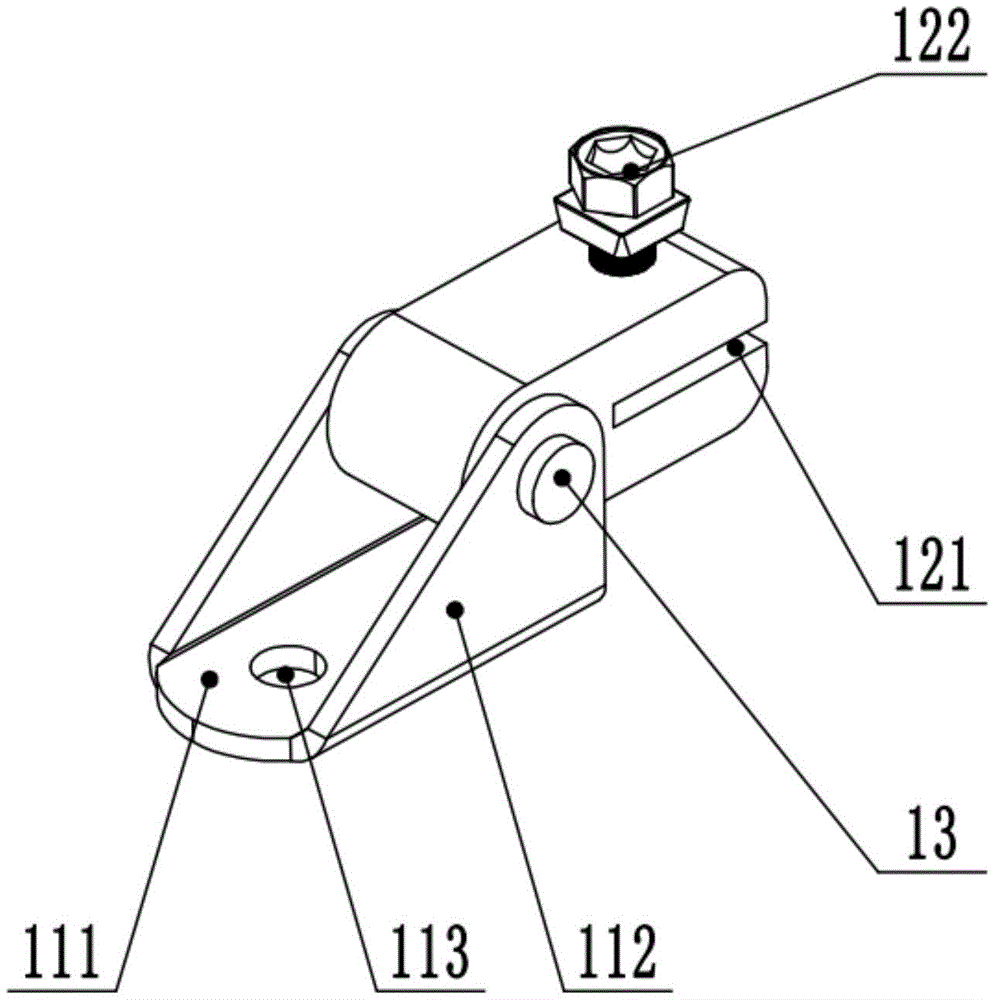
图1为实施例1中上底座的结构示意图;Fig. 1 is the structural representation of the upper base in embodiment 1;
图2为实施例1中下底座的结构示意图;Fig. 2 is the structural representation of lower base in embodiment 1;
图3为实施例1中夹紧座的局部剖视图;3 is a partial cross-sectional view of the clamping seat in Embodiment 1;
图4为实施例2中夹紧座的局部剖视图;4 is a partial cross-sectional view of the clamping seat in Embodiment 2;
图5为实施例3中上连接座的侧视示意图;5 is a schematic side view of the upper connecting seat in
图6为实施例3中下连接座的侧视示意图。FIG. 6 is a schematic side view of the lower connecting seat in
其中,111-上底板,112-上翼板,113-上连接孔,12-上夹紧座12,121-第一开口槽,13-第一固定铆钉,211-下底板,212-下连接板,213-下翼板,214-下连接孔,22-下夹紧座22,221-第二开口槽,23-第二固定铆钉,3-柱形螺纹孔,4-锥形凹孔,5-拧断锥形螺丝。Among them, 111-upper base plate, 112-upper wing plate, 113-upper connecting hole, 12-
具体实施方式Detailed ways
下面通过参考附图来详细说明本实用新型。The present invention will be described in detail below with reference to the accompanying drawings.
实施例1Example 1
一种抗震支吊架用连接底座,包括成对使用的上底座和下底座。所述上底座和下底座分别安装于C型槽钢的两端,固定后即可实现对设备管道的侧向拉撑和纵向拉撑。其中,上底座朝上安装、用于将C型槽钢与楼板墙体或主体结构固定连接,下底座朝下安装,用于将C型槽钢与管道和设备构件固定连接。A connection base for an anti-seismic support and hanger comprises an upper base and a lower base used in pairs. The upper base and the lower base are respectively installed at the two ends of the C-shaped channel steel, and after being fixed, the lateral and longitudinal support of the equipment pipeline can be realized. Among them, the upper base is installed upwards, which is used to fixedly connect the C-shaped channel steel with the floor wall or the main structure, and the lower base is installed downwards, which is used to fixedly connect the C-shaped channel steel with the pipeline and equipment components.
如图1所示,所述上底座由上连接座和上夹紧座12组成,上连接座和上夹紧座12通过第一固定铆钉13铰接连接,上夹紧座12以第一固定铆钉13为轴心大角度旋转,旋转角度不小于180°。As shown in FIG. 1 , the upper base is composed of an upper connecting seat and an
所述上连接座包括一体成型的上底板111和两块上翼板112,两块上翼板112设置在上底板111的两侧且向上弯折呈90°垂直设置;两块上翼板112之间形成夹持上夹紧座12的间隙。在两块上翼板112的顶部对应开设有用于第一固定铆钉13穿过的销孔。在上底板111上还设置有上连接孔113,膨胀螺栓由上连接孔113插入、再固定于墙体。The upper connecting seat includes an integrally formed
具体来说,所述两块上翼板112均为三角形翼板,可以在保证连接强度的情况下便于工人施工操作。Specifically, the two
所述上夹紧座12为方形钢锭加工而成,其尾部设置有与上翼板112的销孔相对应的通孔,第一固定铆钉13依次穿过销孔-通孔-销孔后用螺母固定,实现上连接座和上夹紧座12的固定连接。在上夹紧座12的前端开设有第一开口槽121,所述第一开口槽121的宽度略大于C型槽钢的顶壁厚度,C型槽钢可顺利插入第一开口槽121、并被第一开口槽121的上端壁和下端壁限位夹紧。在第一开口槽121的上方开设有贯穿第一开口槽121上端壁的柱形螺纹孔3,柱形螺纹孔3上设置拧断锥形螺丝5;在第一开口槽121下端壁上开设有锥形凹孔4,锥形凹孔4与柱形螺纹孔3对应设置、其形状与拧断锥形螺丝5的前端相配适。C型槽钢插入第一开口槽121后、旋转拧断锥形螺丝向下紧固,直至拧断锥形螺丝5头部断开,此时拧断锥形螺丝5已穿透槽钢、前端插入锥形凹孔4,将C型槽钢和上夹紧座12牢牢的连接起来。The
如图2所示,所述下底座由下连接座、下夹紧座22、用于连接下连接座和下夹紧座22的第二固定铆钉23组成,下连接座和下夹紧座22通过第二固定铆钉23铰接,下夹紧座22可以第二固定铆钉23为轴心大角度旋转,旋转角度不小于180°。As shown in FIG. 2 , the lower base is composed of a lower connecting seat, a
所述下连接座包括一体成型的下底板211、下连接板212和两块下翼板213。所述下连接板212的前端连接下底板211,下底板211与下连接板212之间呈100°~145°的钝角,便于配合斜撑槽钢的安装角度;在下底板211上开设有下连接孔214,螺栓由下连接孔214穿过、与管道和设备构件连接。所述两块下翼板213设置在下连接板212的尾部两侧、且向上弯折呈90°直角设置,两块下翼板213之间形成夹持下夹紧座22的间隙。在两块下翼板213的顶部对应开设有用于第二固定铆钉23穿过的销孔。The lower connecting seat includes an integrally formed
所述下夹紧座22结构与上夹紧座12的结构基本相同,由方形钢锭加工而成,其尾部设置有与下翼板213的销孔相对应的通孔,第二固定铆钉23依次穿过销孔-通孔-销孔后用螺母固定,实现下连接座和下夹紧座22的固定连接。在下夹紧座22的前端开设有第二开口槽221,第二开口槽221顶部设置有用于紧固的拧断锥形螺丝5;所述第二开口槽221的宽度略大于C型槽钢的顶壁厚度,C型槽钢可顺利插入第二开口槽221、并被第二开口槽221的上端壁和下端壁限位夹紧。在第二开口槽221的下方开设有贯穿开口槽上端壁的柱形螺纹孔3,在第二开口槽221下端壁下开设有与柱形螺纹孔3相对应的锥形凹孔4,锥形凹孔4未贯穿第二开口槽221的下端壁;在柱形螺纹孔3上设置有拧断锥形螺丝5,C型槽钢插入第二开口槽221后旋转拧断锥形螺丝5,直至螺丝前端贯穿槽钢、固定于锥形凹孔4,实现C型槽钢的稳固连接。The structure of the
所述上夹紧座12、下夹紧座22的边角均为圆角。The corners of the upper clamping
实施例2Example 2
本实施例产品结构与实施例1的产品结构基本相同,其区别在于,上夹紧座12与下夹紧座22均为双向可固定。The product structure of this embodiment is basically the same as that of the first embodiment, the difference is that the upper clamping
具体来说,所述第一开口槽121的上端壁和下端壁上均设置有贯穿的柱形螺纹孔3,两个螺纹孔对应设置,如图4所示;拧断锥形螺丝5可从第一开口槽121的任意一面开始拧紧、贯穿C型槽钢后在相对的柱形螺纹孔3上固定。类似的,第二开口槽221的上端壁和下端壁上均设置有贯穿的柱形螺纹孔3,两个柱形螺纹孔3对应设置;拧断锥形螺丝可以从第二开口槽221的任意一面开始拧紧、贯穿C型槽钢后在相对的柱形螺纹孔3上固定。Specifically, the upper end wall and the lower end wall of the
拧断锥形螺丝5可以双向拧入,极大的方便了工人施工,尤其是在较为狭窄的安装区域,可以根据空间和设备安装的具体情况,选择便于操作的一端进行固定,适应性强。The broken
实施例3Example 3
本实施例产品结构与实施例1产品结构的区别之处在于,实施例1中上翼板112、下翼板213均为直角三角形,本实施例产品中的上翼板112、下翼板213均为等腰三角形,销孔设置于等腰三角形的顶端。The difference between the product structure of this embodiment and the product structure of Embodiment 1 is that in Embodiment 1, the
当上翼板112、下翼板213为直角三角形时,夹紧座向翼板直角边一侧旋转时角度较大、而向翼板斜边一侧旋转时角度受限;将上翼板112、下翼板213调整为等腰三角形后,夹紧座向翼板两侧均能获得较大的旋转空间,旋转角度加大,能够满足不同角度的安装连接要求。When the
实施例4Example 4
所述上翼板和下翼板的销孔内壁上均设置有弹性缓冲层。弹性缓冲层可以粘结在销孔内壁,也可采用其他常规方式固定。弹性缓冲层为橡胶层或硅胶层,具有良好的弹性;当连接底座受到地震力时,弹性缓冲层能够吸收一定应力,减少固定铆钉对销孔的冲击力,增加连接座和夹紧座之间的连接稳定性。An elastic buffer layer is arranged on the inner walls of the pin holes of the upper wing plate and the lower wing plate. The elastic buffer layer can be bonded to the inner wall of the pin hole, or fixed in other conventional ways. The elastic buffer layer is a rubber layer or a silicone layer, which has good elasticity; when the connection base is subjected to seismic force, the elastic buffer layer can absorb certain stress, reduce the impact force of the fixed rivet on the pin hole, and increase the gap between the connection base and the clamping base. connection stability.
本实用新型产品可以根据具体的安装要求进行加工。在上述实施例中,所述上夹紧座12、下夹紧座22均由35mm×35mm的方料加工而成,第一开口槽、第二开口槽的宽度均为5mm,开口槽的上端壁、下端壁厚度均为15mm,固定用销孔
常规的C型槽钢的顶壁厚度为2~3mm,相对两侧壁之间的宽度为36mm;当C型槽钢插入开口槽后,开口槽夹住槽钢顶壁的两侧,槽钢的侧壁夹住夹紧座,夹紧座和C型槽钢彼此相互夹持,显著提高了连接稳定性,解决了原本槽钢与夹紧部件单侧连接时两者容易相对分离的问题。The thickness of the top wall of the conventional C-shaped channel steel is 2-3mm, and the width between the opposite two side walls is 36mm; when the C-shaped channel steel is inserted into the open slot, the open slot clamps both sides of the top wall of the channel steel, and the channel steel The side wall of the duct clamps the clamping seat, and the clamping seat and the C-shaped channel steel are clamped to each other, which significantly improves the connection stability and solves the problem that the channel steel and the clamping part are easily separated from each other when they are connected on one side.
以上所述仅为本实用新型的较佳实施例,凡依本实用新型申请专利范围所做的均等变化与修饰,皆应属本实用新型的涵盖范围。The above are only preferred embodiments of the present invention, and all equivalent changes and modifications made according to the scope of the patent application of the present invention shall fall within the scope of the present invention.
Claims (8)
Priority Applications (1)
| Application Number | Priority Date | Filing Date | Title |
|---|---|---|---|
| CN201922430030.7U CN211046292U (en) | 2019-12-30 | 2019-12-30 | Base is connected to antidetonation gallows |
Applications Claiming Priority (1)
| Application Number | Priority Date | Filing Date | Title |
|---|---|---|---|
| CN201922430030.7U CN211046292U (en) | 2019-12-30 | 2019-12-30 | Base is connected to antidetonation gallows |
Publications (1)
| Publication Number | Publication Date |
|---|---|
| CN211046292U true CN211046292U (en) | 2020-07-17 |
Family
ID=71535917
Family Applications (1)
| Application Number | Title | Priority Date | Filing Date |
|---|---|---|---|
| CN201922430030.7U Expired - Fee Related CN211046292U (en) | 2019-12-30 | 2019-12-30 | Base is connected to antidetonation gallows |
Country Status (1)
| Country | Link |
|---|---|
| CN (1) | CN211046292U (en) |
-
2019
- 2019-12-30 CN CN201922430030.7U patent/CN211046292U/en not_active Expired - Fee Related
Similar Documents
| Publication | Publication Date | Title |
|---|---|---|
| CN211351611U (en) | A combined circular tube anti-seismic support hanger | |
| US20140017031A1 (en) | Attach toggle | |
| CN211046292U (en) | Base is connected to antidetonation gallows | |
| CN211693357U (en) | A kind of anti-seismic support hanger for cable bridge | |
| CN219068099U (en) | An Assembled Flexible Photovoltaic Support | |
| CN211344235U (en) | A kind of anti-seismic support hanger for air duct | |
| CN110863674B (en) | Integrated assembled steel construction building | |
| CN209742174U (en) | A curtain wall installation structure | |
| WO2003074805A1 (en) | Point-joint type mounting for glass curtain wall | |
| CN219952642U (en) | Disc buckle type cross bar | |
| CN209151084U (en) | A kind of mounting assembly and photovoltaic bracket of photovoltaic cell | |
| CN213143617U (en) | Installation structure for solving large-span prestress | |
| CN209102314U (en) | Vibration detection bracket | |
| JPH086896Y2 (en) | Ceiling base muscle abuse hardware | |
| CN207572846U (en) | A kind of double catenary clamping devices for erecting cable | |
| KR20070056757A (en) | Scaffolding Clamps | |
| CN114704011B (en) | Mounting structure for curtain | |
| CN111663687A (en) | Suspended Detachable Flexible Connection Stone Curtain Wall System | |
| CN112178018A (en) | A connection structure and an installation structure of an insulator of a suspended angle steel tower | |
| CN217000187U (en) | Building engineering antidetonation connecting piece | |
| CN205577449U (en) | Building slope steel hangs and draws device | |
| CN222277658U (en) | Adjustable bolt assembly structure for support and hanger | |
| CN216767473U (en) | Single-column upward expansion type support | |
| CN211058104U (en) | Curtain wall shock mounting | |
| CN217799887U (en) | Support tooling for bulkhead installation |
Legal Events
| Date | Code | Title | Description |
|---|---|---|---|
| GR01 | Patent grant | ||
| GR01 | Patent grant | ||
| CF01 | Termination of patent right due to non-payment of annual fee | ||
| CF01 | Termination of patent right due to non-payment of annual fee |
Granted publication date: 20200717 |