CN211113236U - Mountain area river course flood discharge box culvert inlet structure - Google Patents
Mountain area river course flood discharge box culvert inlet structure Download PDFInfo
- Publication number
- CN211113236U CN211113236U CN201921102008.3U CN201921102008U CN211113236U CN 211113236 U CN211113236 U CN 211113236U CN 201921102008 U CN201921102008 U CN 201921102008U CN 211113236 U CN211113236 U CN 211113236U
- Authority
- CN
- China
- Prior art keywords
- box culvert
- discharge box
- flood discharge
- guide wall
- overflow weir
- Prior art date
- Legal status (The legal status is an assumption and is not a legal conclusion. Google has not performed a legal analysis and makes no representation as to the accuracy of the status listed.)
- Active
Links
Images




Landscapes
- Barrages (AREA)
Abstract
本实用新型提供了一种山区河道排洪箱涵进口结构,包括排洪箱涵进口及设置在第一河岸和第二河岸之间的溢流堰,溢流堰的上游设置一引水闸,溢流堰的下游建有与排洪箱涵进口连通的导墙,溢流堰的末端与排洪箱涵进口的底板之间设置有渐变陡坡。山区河道常径流下,本实用新型通过溢流堰抬高水位,打开引水闸,引进清水,满足下游景观水面需求,沟道发洪水时,关闭引水闸,洪水通过溢流堰进入渐变陡坡,同时经过导墙引导,实现水流平稳过渡,使得洪水顺利进入排洪箱涵,洪水经过排洪箱涵排放至下游。
The utility model provides an inlet structure of a flood discharge box culvert in a mountain river, which comprises an inlet of the flood discharge box culvert and an overflow weir arranged between the first river bank and the second river bank. There is a guide wall connected to the inlet of the flood discharge box culvert in the downstream of the weir, and a gradient steep slope is set between the end of the overflow weir and the bottom plate of the inlet of the flood discharge box culvert. Under the constant runoff of the mountain river, the utility model raises the water level through the overflow weir, opens the diversion gate, and introduces clean water to meet the demand of the downstream landscape water surface. Guided by the guide wall, the smooth transition of the water flow is realized, so that the flood can smoothly enter the flood discharge box culvert, and the flood water is discharged to the downstream through the flood discharge box culvert.
Description
技术领域technical field
本实用新型属于水利工程中的排洪设计领域,涉及一种山区河道排洪箱涵进口结构。The utility model belongs to the field of flood discharge design in water conservancy projects, and relates to an inlet structure of a flood discharge box culvert in a mountain river.
背景技术Background technique
山区河道具有河道纵坡大,洪水历时短,流速大,两岸土地面积受限的特点,随着山区水景观要求的提高,有限的土地空间很难同时满足景观水面和排洪要求,需要设置排洪箱涵解决水面景观与行洪通道的尖锐矛盾,在箱涵进口需要布置一种分流的进口结构。顺河道方向,进口结构主要起到分洪和引流的作用,即河道常流量下,向下游引水,满足景观用水,在河道发生洪水时,能够将洪水引入排洪箱涵。The mountain river course has the characteristics of large longitudinal slope, short flood duration, large flow velocity, and limited land area on both sides. The flood box culvert solves the sharp contradiction between the water surface landscape and the flood channel, and a diverted inlet structure needs to be arranged at the entrance of the box culvert. Along the direction of the river, the inlet structure mainly plays the role of flood diversion and drainage, that is, under the constant flow of the river, the water is diverted downstream to meet the landscape water consumption. When the river flood occurs, the flood can be introduced into the flood discharge box culvert.
现有技术中,排洪箱涵的分流进口结构通常是在河道上游设置进水闸和分洪闸。如申请号CN00240991.7的实用新型专利公开了一种自动泄洪分洪闸,该分洪闸包括一个上端开口的框架,框架的两侧连接轴套,三角形的闸门两侧连接闸门轴,闸门轴套在轴套内,闸门的上部面积大于闸门的下部面积,闸门的上部质量小于闸门的下部质量,闸门的上部宽度小于框架的上部宽度,闸门的下部宽度大于框架的下部宽度。当洪水超过一定水位时,闸门自动翻转,即可自动泄洪分洪。In the prior art, the diversion inlet structure of the flood discharge box culvert is usually provided with an intake gate and a flood gate at the upstream of the river. For example, the utility model patent with the application number CN00240991.7 discloses an automatic flood discharge flood gate, the flood gate comprises a frame with an open upper end, two sides of the frame are connected with shaft sleeves, two sides of the triangular gate are connected with a gate shaft, and the gate shaft is sleeved on In the shaft sleeve, the upper area of the gate is larger than the lower area of the gate, the upper mass of the gate is smaller than the lower mass of the gate, the upper width of the gate is smaller than the upper width of the frame, and the lower width of the gate is larger than the lower width of the frame. When the flood exceeds a certain water level, the gate is automatically turned over, and the flood can be automatically released and distributed.
申请号CN201303070327.X的发明专利涉及一种城市河流截污箱涵清污分流系统和方法,包括:截污箱涵闸门,在截污箱涵闸门的支流端上游设置连接支流和干流的入河岔道,截污箱涵闸门的截污箱涵端上游设置箱涵水位仪和箱涵流量计,支流在入河闸门上游设置溶氧仪,溶氧仪上游设置与调蓄池连接的调蓄岔道,支流在调蓄池闸门上游设置支流入流水位仪和支流流量计,调蓄岔道中设置调蓄水位仪。本实用新型通过检测水体溶解氧浓度,判断水体污染状况,通过测量水体深度和流量,判断截污箱涵是否发生溢流。选择性调整支流汇入干流、截污箱涵和调蓄池闸门开度,控制由支流进入干流河道、截污箱涵和调蓄池的流量,达到保证清洁水进入干流河道。The invention patent of application number CN201303070327.X relates to an urban river sewage interception box culvert decontamination and diversion system and method, including: a sewage interception box culvert gate, and upstream of the tributary end of the sewage interception box culvert gate is provided. Fork road, box culvert water level meter and box culvert flowmeter are installed upstream of the sewage interception box culvert end of the sewage interception box culvert gate, and a dissolved oxygen meter is installed upstream of the tributary gate, and the adjustment and storage branch road connected to the adjustment and storage tank is installed upstream of the dissolved oxygen meter. , The tributary is set upstream of the regulating and storage tank gate with a tributary inflow water level meter and a tributary flow meter, and a regulating and storage water level meter is set in the regulating and storage fork. The utility model judges the pollution status of the water body by detecting the dissolved oxygen concentration of the water body, and judges whether the sewage interception box culvert overflows by measuring the depth and flow of the water body. Selectively adjust the opening of tributaries into the main stream, sewage interception box culverts and regulating and storage tank gates, and control the flow from tributaries into the main stream channel, sewage interception box culverts and regulating reservoirs, so as to ensure that clean water enters the main stream channel.
但是,上述结构需要管理人员常驻场地,或者时时远程控制,增加工程投资和管理成本;同时,由于山区河道一般较窄,闸门过多也极易影响河道行洪。However, the above structure requires management personnel to be stationed at the site, or remote control from time to time, which increases project investment and management costs; at the same time, because the river channels in mountainous areas are generally narrow, too many gates can easily affect the flood flow of the river channel.
实用新型内容Utility model content
本实用新型的目的在于提供一种山区河道排洪箱涵进口结构,旨在解决现有技术中,闸门过多影响河道行洪,或分洪不善致使水景观设施冲刷的问题。The purpose of the utility model is to provide an inlet structure of a flood discharge box culvert in a mountain river, which aims to solve the problem in the prior art that too many gates affect the flood discharge of the river, or the water landscape facilities are eroded due to poor flood distribution.
为此,本实用新型提供了一种山区河道排洪箱涵进口结构,包括排洪箱涵进口及设置在第一河岸和第二河岸之间的溢流堰,溢流堰的上游设置一引水闸,溢流堰的下游建有与排洪箱涵进口连通的导墙,溢流堰的末端与排洪箱涵进口的底板之间设置有渐变陡坡。To this end, the utility model provides a flood discharge box culvert inlet structure of a mountain river, including a flood discharge box culvert inlet and an overflow weir arranged between the first river bank and the second river bank, and a lead-in port is arranged upstream of the overflow weir. The sluice gate and the downstream of the overflow weir are built with a guide wall that communicates with the inlet of the flood discharge box culvert, and a gradient steep slope is set between the end of the overflow weir and the bottom plate of the flood discharge box culvert inlet.
所述溢流堰为WES曲线堰。The overflow weir is a WES curve weir.
所述导墙由上游导墙、下游导墙及连接上游导墙、下游导墙的衔接挡墙组成。The guide wall is composed of an upstream guide wall, a downstream guide wall, and a connecting retaining wall connecting the upstream guide wall and the downstream guide wall.
所述上游导墙、下游导墙均为圆弧形结构,且下游导墙半径为上游导墙半径的3~4倍。The upstream guide wall and the downstream guide wall are both circular arc structures, and the radius of the downstream guide wall is 3-4 times the radius of the upstream guide wall.
所述上游导墙的高度h上=P+h0+A,The height h of the upstream guide wall=P+h 0 +A,
式中:P为溢流堰堰高,取0.5m~1.0m;In the formula: P is the height of the overflow weir, which is 0.5m to 1.0m;
h0为水深,单位为m;h 0 is the water depth, the unit is m;
A为安全超高,取0.5m。A is the safety superelevation, which is 0.5m.
所述下游导墙的高度h下= h1+AThe height of the downstream guide wall h = h 1 +A
式中:h1为排洪箱涵进口壅高水深,单位为m; A为安全超高,取0.5m。In the formula: h 1 is the high water depth at the inlet of the flood discharge box culvert, the unit is m; A is the safety superelevation, which is taken as 0.5m.
所述渐变陡坡的坡度为1:10~1:20,其长度L=△H/1:10~1:20,式中,△H为溢流堰的末端与排洪箱涵进口的底板之间的高差。The gradient of the gradient steep slope is 1:10~1:20, and its length L=ΔH/1:10~1:20, where ΔH is the distance between the end of the overflow weir and the bottom plate of the flood discharge box culvert inlet. height difference between.
所述溢流堰与上游导墙之间、上游导墙与衔接挡墙之间的衔接处分别设置有橡胶止水带。Rubber waterstops are respectively provided at the joints between the overflow weir and the upstream guide wall and between the upstream guide wall and the connecting retaining wall.
所述引水闸闸门尺寸与溢流堰的堰高一致。The size of the diversion gate is the same as the weir height of the overflow weir.
与现有技术相比本实用新型具有以下有益效果:Compared with the prior art, the utility model has the following beneficial effects:
1.减少了闸门数量,增加了溢流堰的宽度,降低了结构对河道行洪的影响;1. The number of gates is reduced, the width of the overflow weir is increased, and the impact of the structure on the flood discharge of the river is reduced;
2.本实用新型所述的溢流堰采用WES曲线堰,降低水流紊动性;2. The overflow weir of the utility model adopts WES curve weir to reduce the turbulence of water flow;
3. 本实用新型采用溢流堰抬高水位,使得上游有一定的存水量,满足下游景观用水需求;采用渐变陡坡使得水流平稳过渡,同时通过导墙阻挡洪水,防止洪水对下游水景观的冲刷,进而解决了山区河道的分洪和景观引水问题。3. The utility model adopts the overflow weir to raise the water level, so that there is a certain amount of water in the upstream to meet the water demand of the downstream landscape; the gradient steep slope is used to make the water flow smoothly transition, and at the same time, the flood is blocked by the guide wall to prevent the flood from scouring the downstream water landscape. , and then solve the problem of flood diversion and landscape water diversion in mountain rivers.
附图说明Description of drawings
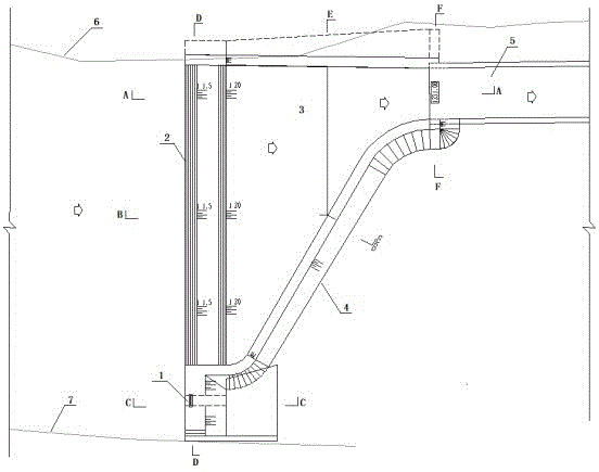
图1是本实用新型所述的排洪箱涵进口平面图;Fig. 1 is the inlet plan view of the flood discharge box culvert described in the present utility model;
图2是图1中A-A剖面图;Fig. 2 is A-A sectional view in Fig. 1;
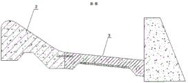
图3是图1中B-B剖面图;Fig. 3 is B-B sectional view in Fig. 1;
图4是图1中C-C剖面图;Fig. 4 is C-C sectional view in Fig. 1;
图5是图1中D-D剖面图;Fig. 5 is D-D sectional view in Fig. 1;
图6是图1中E-E剖面图。FIG. 6 is an E-E sectional view in FIG. 1 .
附图标记说明:1、引水闸;2、溢流堰;3、导墙;4、渐变陡坡;5、排洪箱涵进口,6、第一河岸;7、第二河岸。Description of reference numerals: 1. Diversion gate; 2. Overflow weir; 3. Guide wall; 4. Gradient steep slope; 5. Inlet of flood discharge box culvert; 6. First river bank;
具体实施方式Detailed ways
在本实用新型的描述中,需说明的是,术语“第一”、“第二”仅用于描述目的,而不能理解为指示或暗示相对重要性。术语“安装”、“相连”、“连接”应做广义理解,例如,可以是固定连接,也可以是可拆卸连接,或一体地连接;可以是直接相连,也可以通过中间媒介间接相连,可以是两个元件内部的连通。对于本领域的普通技术人员而言,可以具体情况理解上述术语在本实用新型中的具体含义。In the description of the present invention, it should be noted that the terms "first" and "second" are only used for description purposes, and cannot be understood as indicating or implying relative importance. The terms "installed", "connected" and "connected" should be understood in a broad sense, for example, it may be a fixed connection, a detachable connection, or an integral connection; it may be directly connected or indirectly connected through an intermediate medium, and it may be is the connection between the two elements. For those of ordinary skill in the art, the specific meanings of the above terms in the present invention can be understood in specific situations.
现参考附图介绍本实用新型的示例性实施方式,然而,本实用新型可以用许多不同的形式来实施,并且不局限于此处描述的实施例,提供这些实施例是为了详尽地且完全地公开本实用新型,并且向所属技术领域的技术人员充分传达本实用新型的范围。对于表示在附图中的示例性实施方式中的术语并不是对本实用新型的限定。在附图中,相同的单元/元件使用相同的附图标记。Exemplary embodiments of the present invention will now be described with reference to the accompanying drawings, however, the present invention may be embodied in many different forms and is not limited to the embodiments described herein, which are provided for the purpose of being thorough and complete. The present invention is disclosed and the scope of the present invention is fully conveyed to those skilled in the art. The terms used in the exemplary embodiments shown in the accompanying drawings are not intended to limit the invention. In the drawings, the same elements/elements are given the same reference numerals.
除非另有说明,此处使用的术语(包括科技术语)对所属技术领域的技术人员具有通常的理解含义。另外,可以理解的是,以通常使用的词典限定的术语,应当被理解为与其相关领域的语境具有一致的含义,而不应该被理解为理想化的或过于正式的意义。Unless otherwise defined, terms (including scientific and technical terms) used herein have the commonly understood meanings to those skilled in the art. In addition, it is to be understood that terms defined in commonly used dictionaries should be construed as having meanings consistent with the context in the related art, and should not be construed as idealized or overly formal meanings.
实施例1Example 1
如图1所示,一种山区河道排洪箱涵进口结构,包括排洪箱涵进口5及设置在第一河岸6和第二河岸7之间的溢流堰2,溢流堰2的上游设置一引水闸1,溢流堰2的下游建有与排洪箱涵进口5连通的导墙3,溢流堰2的末端与排洪箱涵进口5的底板之间设置有渐变陡坡4。As shown in Figure 1, a flood discharge box culvert inlet structure of a mountain river includes a flood discharge box culvert inlet 5 and an
本实用新型通过溢流堰2和引水闸1共同拦段河床,协调控制水流,山区河道常径流下,通过溢流堰2抬高水位,打开引水闸1,引进清水,山区河道发洪水时,关闭引水闸1,洪水越过溢流堰2,堰后洪水在导墙3和渐变陡坡4的引导下进入排洪箱涵进口5,进而,通过排洪箱涵通向河道下游。The utility model uses the
实施例2Example 2
在实施例1的基础上,如图2所示,进一步地,所述溢流堰2为WES曲线堰,溢流堰的堰顶面曲线方程为:
WES曲线堰能够尽可能的降低水流紊动性。The WES curve weir can reduce the turbulence of water flow as much as possible.
进一步地,如图4、图5所示,所述溢流堰2堰高P为0.5~1.0m,所述引水闸1布置于溢流堰2轴线,引水闸1在溢流堰2抬高水位时,引水闸1的闸门尺寸与堰高一致,优选地,引水闸1采用1.0m×1.0m的矩形闸。Further, as shown in FIGS. 4 and 5 , the weir height P of the
实施例3Example 3
在上述实施例的基础上,进一步地,如图3、图6所示,所述导墙3主要为阻挡通过溢流堰2后的洪水,保护下游水景观设施,导墙3为曲线结构,由上游导墙、下游导墙及连接上游导墙、下游导墙的衔接段挡墙组成。On the basis of the above-mentioned embodiment, further, as shown in Fig. 3 and Fig. 6 , the
优选地,所述上游导墙、下游导墙均为圆弧形结构,使得水流平顺,增加水流过流能力,下游导墙与游导墙相比水面较窄,容易形成急流,因此,下游导墙半径应大于上游导墙半径,本实例中下游导墙半径为上游导墙半径4倍。Preferably, the upstream guide wall and the downstream guide wall are arc-shaped structures, so that the water flow is smooth and the water flow capacity is increased. The wall radius should be larger than the upstream guide wall radius. In this example, the downstream guide wall radius is 4 times the upstream guide wall radius.
进一步地,所述上游导墙的高度h上=P+h0+A,式中:P为WES曲线堰2堰高,取0.5m~1.0m;h0为堰上水深,通过堰流流量公式计算确定,A为安全超高,取0.5m。Further, the height h of the upstream guide wall=P+h 0 +A, where: P is the height of the
所述下游导墙的高度h下= h1+A,式中:h1为排洪箱涵进口5壅水高度,通过隧洞半有压流公式计算确定;A为安全超高,取0.5m。The height h of the downstream guide wall = h 1 +A, where: h 1 is the height of the backwater at the inlet of the flood discharge box culvert 5, which is calculated and determined by the semi-pressurized flow formula of the tunnel; A is the safety superelevation, which is 0.5m .
所述堰流流量公式、隧洞半有压流公式及其计算方法均为现有公知技术,在此不再赘述。The weir flow flow formula, the tunnel semi-pressurized flow formula and the calculation method thereof are all known in the prior art, and will not be repeated here.
实施例4Example 4
在上述实施例的基础上,进一步地,所述渐变陡坡4主要为衔接溢流堰2和排洪箱涵进口,渐变陡坡4坡度应尽可能缓,保证洪水有充分的收缩过程,降低旋流发生的可能性,本实用新型推荐渐变陡坡4的坡度为1:10~1:20,其长度L=△H/(1:10~1:2),△H为溢流堰2末端与排洪箱涵进口5底板之间的高差。On the basis of the above embodiment, further, the gradient steep slope 4 mainly connects the
实施例5Example 5
本实用新型的施工步骤,包括:步骤一,靠近引水闸1位置实施纵向围堰,纵向围堰采用混凝土围堰,在引水闸1上、下游分别布置横向围堰,横向围堰采用土石结构,纵向围堰嵌入横向围堰中,横向围堰与纵向围堰应封闭,必要时设置止水,围堰施工满足现行《水利水电工程施工组织设计规范》的要求;步骤二,施工引水闸,施工满足现行《水闸施工规范》的要求;步骤三,先拆除下游围堰,在拆除上游围堰最后拆除纵向围堰;步骤四,在溢流堰2上、下游实施横向围堰,横向围堰布置于溢流堰2、导墙3、渐变陡坡4的外侧,横向围堰与引水闸1紧密相连;步骤五,实施溢流堰2、导墙3、渐变陡坡4,施工中应先实施溢流堰,在实施导墙,最后实施变陡坡4,施工满足现行《水工混凝土施工规范》的要求;步骤六,拆除围堰,先拆除下游围堰,在拆除上游围堰。The construction steps of the present utility model include: step 1, implementing a longitudinal cofferdam near the water diversion gate 1, using a concrete cofferdam for the longitudinal cofferdam, arranging a horizontal cofferdam on the upstream and downstream of the diversion gate 1 respectively, and the lateral cofferdam adopts an earth-rock structure, The vertical cofferdam is embedded in the horizontal cofferdam, the horizontal cofferdam and the vertical cofferdam should be closed, and the water stop should be set up if necessary. The construction of the cofferdam meets the requirements of the current "Code for Design of Construction Organization of Water Conservancy and Hydropower Engineering"; Meet the requirements of the current "Sluice Construction Specifications";
本实用新型的运行管理步骤为:景观补水时打开引水闸1引水,清水通过引水闸1进入下游景观水面,汛期时关闭引水闸1,河道通过溢流堰2溢流泄洪,定期对溢流堰上游的淤沙进行清理,定期对结构进行维护修理,增加结构的使用寿命。The operation and management steps of the utility model are as follows: when the landscape is replenished, the water diversion gate 1 is opened to divert water, the clear water enters the downstream landscape water surface through the diversion gate 1, the diversion gate 1 is closed during the flood season, the river channel overflows and discharges the flood through the
Claims (9)
Priority Applications (1)
| Application Number | Priority Date | Filing Date | Title |
|---|---|---|---|
| CN201921102008.3U CN211113236U (en) | 2019-07-15 | 2019-07-15 | Mountain area river course flood discharge box culvert inlet structure |
Applications Claiming Priority (1)
| Application Number | Priority Date | Filing Date | Title |
|---|---|---|---|
| CN201921102008.3U CN211113236U (en) | 2019-07-15 | 2019-07-15 | Mountain area river course flood discharge box culvert inlet structure |
Publications (1)
| Publication Number | Publication Date |
|---|---|
| CN211113236U true CN211113236U (en) | 2020-07-28 |
Family
ID=71705169
Family Applications (1)
| Application Number | Title | Priority Date | Filing Date |
|---|---|---|---|
| CN201921102008.3U Active CN211113236U (en) | 2019-07-15 | 2019-07-15 | Mountain area river course flood discharge box culvert inlet structure |
Country Status (1)
| Country | Link |
|---|---|
| CN (1) | CN211113236U (en) |
Cited By (1)
| Publication number | Priority date | Publication date | Assignee | Title |
|---|---|---|---|---|
| CN117107786A (en) * | 2023-07-05 | 2023-11-24 | 陕西冶金设计研究院有限公司 | A method for managing hidden risks in tailings ponds |
-
2019
- 2019-07-15 CN CN201921102008.3U patent/CN211113236U/en active Active
Cited By (1)
| Publication number | Priority date | Publication date | Assignee | Title |
|---|---|---|---|---|
| CN117107786A (en) * | 2023-07-05 | 2023-11-24 | 陕西冶金设计研究院有限公司 | A method for managing hidden risks in tailings ponds |
Similar Documents
| Publication | Publication Date | Title |
|---|---|---|
| CN115305864B (en) | A method and system for comprehensive treatment of coastal silted rivers | |
| CN112281770B (en) | Flood discharge structure adopting bottom hole and surface hole combined flood discharge and energy dissipation | |
| CN114775510B (en) | Ecological river and lake system with controllable combination and construction method thereof | |
| CN104963322A (en) | Hydraulic junction facility | |
| CN110528475A (en) | A kind of hydraulic engineering water intake system | |
| CN211113236U (en) | Mountain area river course flood discharge box culvert inlet structure | |
| CN106702968A (en) | Arc type overflow dam capable of automatically washing away sand and reducing siltation and running method of arc type overflow dam | |
| CN202214710U (en) | Overflow and water discharge integrated sluice weir | |
| CN210562502U (en) | Integrated hydraulic intercepting well | |
| CN211665715U (en) | High-low dam and water taking structure | |
| CN116856361B (en) | A sand retaining and discharging structure for the lower reservoir of a pumped storage power station and its operation method | |
| CN210562057U (en) | Riverbed water intake structure for forward water taking of hydropower station | |
| CN112081063A (en) | Go into sea mouth and fall siphon system | |
| CN219930883U (en) | Landscape overflow weir with purifying system | |
| CN217839763U (en) | Highway bridge culvert steep slope culvert export drainage structures | |
| CN212248058U (en) | Go into sea mouth and fall siphon system | |
| CN116289817A (en) | A water inlet structure of a high head hydropower station without a sedimentation tank and a sedimentation and discharge method | |
| CN208220838U (en) | Tunnel Engineering crosses underground river transverse direction temporary drainage construction | |
| CN105603942B (en) | Dykes and dams super standard flood flood diversion siphon pipe band | |
| CN116464004A (en) | Flood discharge canal and fishway combined system | |
| CN211948317U (en) | Ecological flow drainage facility for constructed diversion canal type rural hydropower station | |
| CN210031716U (en) | A reservoir overflow device | |
| CN223951716U (en) | Ecological water release structure during diversion tunnel closure period | |
| CN219973103U (en) | Low-water-head landscape ecological weir capable of preventing silting and duckweed | |
| CN220433802U (en) | Water taking structure in hydraulic engineering |
Legal Events
| Date | Code | Title | Description |
|---|---|---|---|
| GR01 | Patent grant | ||
| GR01 | Patent grant |