CN211646830U - Detachable wall structure of independent thermostatic chamber - Google Patents
Detachable wall structure of independent thermostatic chamber Download PDFInfo
- Publication number
- CN211646830U CN211646830U CN201922213126.8U CN201922213126U CN211646830U CN 211646830 U CN211646830 U CN 211646830U CN 201922213126 U CN201922213126 U CN 201922213126U CN 211646830 U CN211646830 U CN 211646830U
- Authority
- CN
- China
- Prior art keywords
- wall
- plate
- wall body
- asbestos
- detachable
- Prior art date
- Legal status (The legal status is an assumption and is not a legal conclusion. Google has not performed a legal analysis and makes no representation as to the accuracy of the status listed.)
- Expired - Fee Related
Links
- 239000010425 asbestos Substances 0.000 claims abstract description 36
- 229910052895 riebeckite Inorganic materials 0.000 claims abstract description 36
- 238000009413 insulation Methods 0.000 claims abstract description 25
- 238000007789 sealing Methods 0.000 claims description 15
- 239000000853 adhesive Substances 0.000 claims description 3
- 230000001070 adhesive effect Effects 0.000 claims description 3
- 230000001681 protective effect Effects 0.000 abstract description 25
- 230000000694 effects Effects 0.000 abstract description 9
- 238000003780 insertion Methods 0.000 description 7
- 230000037431 insertion Effects 0.000 description 7
- 238000010586 diagram Methods 0.000 description 3
- 238000009434 installation Methods 0.000 description 3
- 238000000034 method Methods 0.000 description 3
- 229940079593 drug Drugs 0.000 description 2
- 239000003814 drug Substances 0.000 description 2
- 230000009286 beneficial effect Effects 0.000 description 1
- 230000007547 defect Effects 0.000 description 1
- 238000005516 engineering process Methods 0.000 description 1
- 239000000463 material Substances 0.000 description 1
- 238000012986 modification Methods 0.000 description 1
- 230000004048 modification Effects 0.000 description 1
- 238000003466 welding Methods 0.000 description 1
Images



Landscapes
- Thermal Insulation (AREA)
Abstract
本实用新型公开了一种独立恒温室可拆卸式墙体结构,包括第一墙体、顶墙和连接块,所述第一墙体的内侧表面开设有卡槽,且第一墙体的边侧连接有第二墙体,并且第二墙体的左右两端固定有卡块,所述第二墙体边侧最上方的卡块表面开设有限位孔,所述第一墙体和第二墙体的表面均开设有滑槽,且所述防护板的下方粘接设置有橡胶垫,所述顶墙的下方四边设置有固定插杆,所述第一墙体和第二墙体的下方固定安装有万向轮。该独立恒温室可拆卸式墙体结构,第一墙体和第二墙体的内侧均设置有第一石棉板和第二石棉板以及橡胶材质的隔热板,能够通过2个石棉板和隔热板的使用,提高该墙体的保温效果。

The utility model discloses a detachable wall structure of an independent constant temperature chamber, which comprises a first wall, a top wall and a connecting block. A clamping groove is provided on the inner surface of the first wall, and the edge of the first wall is provided with a clamping groove. The side is connected with a second wall body, and the left and right ends of the second wall body are fixed with clamping blocks, the surface of the uppermost clamping block on the side of the second wall body is provided with a limiting hole, the first wall body and the second wall body are The surface of the wall is provided with a chute, and the bottom of the protective plate is bonded with a rubber pad, the bottom four sides of the top wall are provided with fixed insert rods, and the bottom of the first wall and the second wall are The universal wheel is fixedly installed. In the detachable wall structure of the independent constant temperature chamber, the inner sides of the first wall and the second wall are provided with a first asbestos board, a second asbestos board and a rubber heat insulation board, which can pass through the two asbestos boards and the insulation board. The use of hot plate improves the thermal insulation effect of the wall.
Description
技术领域technical field
本实用新型涉及医药厂房独立恒温室相关技术领域,具体为一种独立恒温室可拆卸式墙体结构。The utility model relates to the related technical field of an independent constant temperature chamber of a medical workshop, in particular to a detachable wall structure of an independent constant temperature chamber.
背景技术Background technique
医药厂房独立恒温室是保存药品的重要场所,其由四面墙体和顶墙所构成,在医药厂房中常通过搭建临时独立恒温室对特殊药物进行储存,而对于现有的医药厂房独立恒温室墙体的结构来说,还是存有部分缺陷,比如:The independent constant temperature room of the pharmaceutical workshop is an important place for storing medicines. It consists of four walls and a top wall. In the pharmaceutical workshop, special drugs are often stored by building a temporary independent constant temperature room. In terms of the structure of the body, there are still some defects, such as:
现有的独立恒温室墙体结构的保温效果较差,内部温度容易散失,并且不方便墙体与墙体之间的拆卸,使用效果较差,因此我们提出一种独立恒温室可拆卸式墙体结构,以便解决上述中所存在的问题。The existing wall structure of the independent constant temperature chamber has poor thermal insulation effect, the internal temperature is easy to dissipate, and it is inconvenient to disassemble between the walls and the use effect is poor. Therefore, we propose a detachable wall of the independent constant temperature chamber. body structure in order to solve the above problems.
实用新型内容Utility model content
本实用新型的目的在于提供一种独立恒温室可拆卸式墙体结构,以解决上述背景技术提出现有独立恒温室墙体结构的保温效果较差,内部温度容易散失,并且不方便墙体与墙体之间的拆卸,使用效果较差的问题。The purpose of the utility model is to provide a detachable wall structure of an independent constant temperature chamber, in order to solve the above-mentioned background technology, the existing wall structure of an independent constant temperature chamber has poor thermal insulation effect, the internal temperature is easily lost, and it is inconvenient for the wall to be separated from the wall. The disassembly between the walls is a problem that the use effect is poor.
为实现上述目的,本实用新型提供如下技术方案:一种独立恒温室可拆卸式墙体结构,包括第一墙体、顶墙和连接块,所述第一墙体的内侧表面开设有卡槽,且第一墙体的边侧连接有第二墙体,并且第二墙体的左右两端固定有卡块,所述第二墙体边侧最上方的卡块表面开设有限位孔,所述第一墙体和第二墙体的表面均开设有滑槽,且滑槽上连接有防护板,并且防护板的左侧固定有固定块,所述防护板的下方粘接设置有橡胶垫,且防护板的上当内侧设置有密封条,所述顶墙的下方四边设置有固定插杆,所述第一墙体和第二墙体的下方固定安装有万向轮。In order to achieve the above purpose, the utility model provides the following technical solutions: a detachable wall structure of an independent constant temperature chamber, comprising a first wall, a top wall and a connecting block, and the inner surface of the first wall is provided with a card slot , and the side of the first wall is connected with a second wall, and the left and right ends of the second wall are fixed with clamping blocks, and the surface of the uppermost clamping block on the side of the second wall is provided with limited holes, so The surfaces of the first wall body and the second wall body are both provided with chute, and the chute is connected with a protective plate, and the left side of the protective plate is fixed with a fixing block, and the bottom of the protective plate is glued and provided with a rubber pad , and a sealing strip is arranged on the inner side of the upper side of the protective plate, fixed insertion rods are arranged on the lower four sides of the top wall, and universal wheels are fixedly installed under the first wall and the second wall.
优选的,所述第一墙体由外板、第一石棉板、隔热板、第二石棉板和内板构成,且外板内侧粘接设置有第一石棉板,第一石棉板的内表面连接有隔热板,且隔热板的内表面粘接设置有第二石棉板,第二石棉板的外侧固定连接有内板。Preferably, the first wall is composed of an outer panel, a first asbestos panel, a heat insulating panel, a second asbestos panel and an inner panel, and the inner side of the outer panel is bonded with a first asbestos panel, and the inner side of the first asbestos panel is The surface is connected with a heat insulation board, and the inner surface of the heat insulation board is bonded with a second asbestos board, and the outer side of the second asbestos board is fixedly connected with an inner board.
优选的,所述第一石棉板和第二石棉板关于隔热板的中轴线对称设置,且隔热板采用橡胶材质。Preferably, the first asbestos board and the second asbestos board are symmetrically arranged with respect to the central axis of the heat insulation board, and the heat insulation board is made of rubber.
优选的,所述第二墙体的内部结构与第一墙体的内部结构相同,且第二墙体通过左右两端的卡块与第一墙体内表面的卡槽构成卡合连接。Preferably, the internal structure of the second wall is the same as the internal structure of the first wall, and the second wall is connected with the clipping grooves on the inner surface of the first wall through the clips at the left and right ends.
优选的,所述防护板通过固定块与滑槽构成卡合连接的滑动结构,且防护板底部的橡胶垫的下端面与万向轮的最低端在同一水平面上。Preferably, the protective plate forms a sliding structure in a snap connection with the chute through the fixing block, and the lower end surface of the rubber pad at the bottom of the protective plate and the lowest end of the universal wheel are on the same level.
优选的,所述顶墙与固定插杆为垂直分布,且固定插杆的外径与卡块表面的限位孔的内径相吻合。Preferably, the top wall and the fixed insertion rod are vertically distributed, and the outer diameter of the fixed insertion rod is consistent with the inner diameter of the limiting hole on the surface of the clamping block.
优选的,所述密封条与防护板的连接方式为粘接连接,且密封条的厚度与防护板到第一墙体之间的距离相等。Preferably, the sealing strip and the protective plate are connected by adhesive connection, and the thickness of the sealing strip is equal to the distance between the protective plate and the first wall.
与现有技术相比,本实用新型的有益效果是:该独立恒温室可拆卸式墙体结构;Compared with the prior art, the beneficial effects of the utility model are: the detachable wall structure of the independent constant temperature chamber;
(1)第一墙体和第二墙体的内侧均设置有第一石棉板和第二石棉板以及橡胶材质的隔热板,能够通过2个石棉板和隔热板的使用,提高该墙体的保温效果,避免温度从墙体传出的问题;(1) The inner sides of the first wall and the second wall are provided with a first asbestos board, a second asbestos board and a rubber insulation board, which can improve the wall by using two asbestos boards and insulation boards. The thermal insulation effect of the body can avoid the problem of temperature being transmitted from the wall;
(2)设置有第二墙体的两端通过卡块与第一墙体的边侧构成卡合连接,并配合顶墙下方固定插杆的使用,方便了该恒温室的拆卸与安装,提高了该墙体的使用;(2) The two ends of the second wall are provided with the two ends of the second wall to form a snap connection with the side of the first wall, and cooperate with the use of the fixed insertion rod under the top wall, which facilitates the disassembly and installation of the constant temperature chamber, and improves the use of the wall;
(3)设置有防护板、橡胶垫和万向轮,能够通过滑动防滑板,使第一墙体和第二墙体下方的万向轮显露出来,方便了第一墙体和第二墙体的移动,同时防护板下方的橡胶垫和防护板上方内侧的密封条,能够方便墙体使用时对墙体下方进行密封,提高箱体的使用效果。(3) A protective plate, a rubber pad and a universal wheel are provided, and the universal wheel under the first wall and the second wall can be exposed by sliding the anti-skid plate, which is convenient for the first wall and the second wall. At the same time, the rubber pad under the protective plate and the sealing strip on the inner side above the protective plate can facilitate the sealing of the bottom of the wall when the wall is in use, and improve the use effect of the box.
附图说明Description of drawings
图1为本实用新型俯剖视结构示意图;Fig. 1 is the top sectional structure schematic diagram of the utility model;
图2为本实用新型第一墙体右视结构示意图;Fig. 2 is the right side structural schematic diagram of the first wall of the present invention;
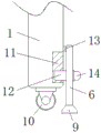
图3为本实用新型防护板与第一墙体连接结构示意图;3 is a schematic diagram of the connection structure between the protective plate and the first wall of the present invention;
图4为本实用新型第二墙体侧视结构示意图。4 is a schematic side view of the second wall structure of the present invention.
图中:1、第一墙体;101、外板;102、第一石棉板;103、隔热板;104、第二石棉板;105、内板;2、卡槽;3、第二墙体;4、卡块;5、限位孔;6、防护板;7、顶墙;8、固定插杆;9、橡胶垫;10、万向轮;11、滑槽;12、固定块;13、密封条;14、连接块。In the figure: 1, the first wall; 101, the outer plate; 102, the first asbestos plate; 103, the heat insulation plate; 104, the second asbestos plate; 105, the inner plate; 2, the card slot; 3, the second wall body; 4, clamping block; 5, limit hole; 6, protective plate; 7, top wall; 8, fixed insertion rod; 9, rubber pad; 10, universal wheel; 11, chute; 12, fixed block; 13. Sealing strip; 14. Connecting block.
具体实施方式Detailed ways
下面将结合本实用新型实施例中的附图,对本实用新型实施例中的技术方案进行清楚、完整地描述,显然,所描述的实施例仅仅是本实用新型一部分实施例,而不是全部的实施例。基于本实用新型中的实施例,本领域普通技术人员在没有做出创造性劳动前提下所获得的所有其他实施例,都属于本实用新型保护的范围。The technical solutions in the embodiments of the present utility model will be clearly and completely described below with reference to the accompanying drawings in the embodiments of the present utility model. Obviously, the described embodiments are only a part of the embodiments of the present utility model, rather than all the implementations. example. Based on the embodiments of the present invention, all other embodiments obtained by those of ordinary skill in the art without creative work fall within the protection scope of the present invention.
请参阅图1-4,本实用新型提供一种技术方案:一种独立恒温室可拆卸式墙体结构,包括第一墙体1、外板101、第一石棉板102、隔热板103、第二石棉板104、内板105、卡槽2、第二墙体3、卡块4、限位孔5、防护板6、顶墙7、固定插杆8、橡胶垫9、万向轮10、滑槽11、固定块12、密封条13和连接块14,第一墙体1的内侧表面开设有卡槽2,且第一墙体1的边侧连接有第二墙体3,并且第二墙体3的左右两端固定有卡块4,第二墙体3边侧最上方的卡块4表面开设有限位孔5,第一墙体1和第二墙体3的表面均开设有滑槽11,且滑槽11上连接有防护板6,并且防护板6的左侧固定有固定块12,防护板6的下方粘接设置有橡胶垫9,且防护板6的上当内侧设置有密封条13,顶墙7的下方四边设置有固定插杆8,第一墙体1和第二墙体3的下方固定安装有万向轮10。1-4, the present utility model provides a technical solution: a detachable wall structure of an independent constant temperature chamber, comprising a
如图1中第一墙体1由外板101、第一石棉板102、隔热板103、第二石棉板104和内板105构成,且外板101内侧粘接设置有第一石棉板102,第一石棉板102的内表面连接有隔热板103,且隔热板103的内表面粘接设置有第二石棉板104,第二石棉板104的外侧固定连接有内板105,第一石棉板102和第二石棉板104关于隔热板103的中轴线对称设置,且隔热板103采用橡胶材质,提高该墙体的保温效果。As shown in FIG. 1 , the
如图1、图2和图4中第二墙体3的内部结构与第一墙体1的内部结构相同,且第二墙体3通过左右两端的卡块4与第一墙体1内表面的卡槽2构成卡合连接,方便了墙体之间的拆卸,如图3中防护板6通过固定块12与滑槽11构成卡合连接的滑动结构,且防护板6底部的橡胶垫9的下端面与万向轮10的最低端在同一水平面上,有效密封墙体底部,如图2中顶墙7与固定插杆8为垂直分布,且固定插杆8的外径与卡块4表面的限位孔5的内径相吻合,方便墙体顶部的安装,如图3中密封条13与防护板6的连接方式为粘接连接,且密封条13的厚度与防护板6到第一墙体1之间的距离相等,避免内部温度从墙体底部散出。As shown in Figures 1, 2 and 4, the internal structure of the
工作原理:首先,在使用时,可通过第二墙体3两端卡块4插入第一墙体1内侧表面开设的卡槽2中,方便了该独立恒温室四面墙体的组装,再将顶墙7下方的固定插杆8与第二墙体3最上方卡块4表面的限位孔5相对应,方便了顶墙7的安装,以便该独立恒温室构成,在使用时,第一墙体1和第二墙体3内部设置的第一石棉板102和第二石棉板104以及橡胶材质的隔热板103,能够有效的提高该墙体的保温效果,在拆卸时,可向上滑动防护板6,使第一墙体1和第二墙体3底部的万向轮10显露出来,方便了第一墙体1和第二墙体3拆卸后的移动,同时防护板6底部的橡胶垫9和上方内侧密封条13能够有效的对该墙体在组合后底部的密封,避免内部温度从墙体底部散出的问题,这就是该独立恒温室可拆卸式墙体结构的使用原理,本说明书中未作详细描述的内容属于本领域专业技术人员公知的现有技术。Working principle: First of all, when in use, the
本实用新型使用到的标准零件均可以从市场上购买,异形件根据说明书的和附图的记载均可以进行订制,各个零件的具体连接方式均采用现有技术中成熟的螺栓、铆钉、焊接等常规手段,机械、零件和设备均采用现有技术中,常规的型号,加上电路连接采用现有技术中常规的连接方式,在此不再详述,本说明书中未作详细描述的内容属于本领域专业技术人员公知的现有技术。The standard parts used in the utility model can be purchased from the market, the special-shaped parts can be customized according to the description in the specification and the drawings, and the specific connection method of each part adopts the mature bolts, rivets and welding in the prior art. and other conventional means, the machinery, parts and equipment all adopt the conventional models in the prior art, and the circuit connection adopts the conventional connection method in the prior art, which will not be described in detail here, and the content that is not described in detail in this specification. It belongs to the prior art known to those skilled in the art.
尽管参照前述实施例对本实用新型进行了详细的说明,对于本领域的技术人员来说,其依然可以对前述各实施例所记载的技术方案进行修改,或者对其中部分技术特征进行等同替换,凡在本实用新型的精神和原则之内,所作的任何修改、等同替换、改进等,均应包含在本实用新型的保护范围之内。Although the present invention has been described in detail with reference to the foregoing embodiments, for those skilled in the art, it is still possible to modify the technical solutions described in the foregoing embodiments, or perform equivalent replacements for some of the technical features. Within the spirit and principle of the present utility model, any modifications, equivalent replacements, improvements, etc. made shall be included within the protection scope of the present utility model.
Claims (7)
Priority Applications (1)
| Application Number | Priority Date | Filing Date | Title |
|---|---|---|---|
| CN201922213126.8U CN211646830U (en) | 2019-12-11 | 2019-12-11 | Detachable wall structure of independent thermostatic chamber |
Applications Claiming Priority (1)
| Application Number | Priority Date | Filing Date | Title |
|---|---|---|---|
| CN201922213126.8U CN211646830U (en) | 2019-12-11 | 2019-12-11 | Detachable wall structure of independent thermostatic chamber |
Publications (1)
| Publication Number | Publication Date |
|---|---|
| CN211646830U true CN211646830U (en) | 2020-10-09 |
Family
ID=72695513
Family Applications (1)
| Application Number | Title | Priority Date | Filing Date |
|---|---|---|---|
| CN201922213126.8U Expired - Fee Related CN211646830U (en) | 2019-12-11 | 2019-12-11 | Detachable wall structure of independent thermostatic chamber |
Country Status (1)
| Country | Link |
|---|---|
| CN (1) | CN211646830U (en) |
-
2019
- 2019-12-11 CN CN201922213126.8U patent/CN211646830U/en not_active Expired - Fee Related
Similar Documents
| Publication | Publication Date | Title |
|---|---|---|
| CN111852258A (en) | An L-shaped edge-sealing aluminum profile | |
| CN211646830U (en) | Detachable wall structure of independent thermostatic chamber | |
| US20180229460A1 (en) | Quick mold clamping device | |
| CN206976443U (en) | A kind of battery box structure | |
| CN104482356A (en) | Heat insulation pad block | |
| CN207040110U (en) | A high-efficiency and energy-saving heat sink assembly that is easy to disassemble | |
| CN204421300U (en) | A kind of associating flange composite air duct | |
| CN206992098U (en) | Semiconductor-type heat sink | |
| CN211481598U (en) | A kind of PCB soft and hard combination board | |
| CN204947523U (en) | A kind of cast-type bus duct connector | |
| CN204288111U (en) | Novel portable computer radiator | |
| CN206413334U (en) | A driver and a governor | |
| CN205536454U (en) | Air-conditioning cabinet cabinet connection structure and air-conditioning cabinet cabinet having the same | |
| CN206564759U (en) | A combined heat sink | |
| CN210891572U (en) | Pressing plate for LED equipment | |
| CN207585390U (en) | A high-efficiency energy-saving radiator | |
| CN218091380U (en) | Thermal insulation material with metal frame protective edge | |
| CN223243006U (en) | A cold bridge prevention box for air handling units used in nuclear power plants | |
| CN222118586U (en) | Fireproof elevator insulation board | |
| CN206946416U (en) | A kind of Novel laptop cooler | |
| CN105180569A (en) | Assembly method for vacuum heat insulation plate | |
| CN210869205U (en) | Energy-saving pig house heating installation conveyor | |
| CN219914503U (en) | A temperature and humidity sensor for buildings | |
| CN220620525U (en) | Building energy-saving heat-insulating board convenient to assemble | |
| CN204627785U (en) | The discharge manifold sealing gasket of integrated thermal baffle |
Legal Events
| Date | Code | Title | Description |
|---|---|---|---|
| GR01 | Patent grant | ||
| GR01 | Patent grant | ||
| CF01 | Termination of patent right due to non-payment of annual fee | ||
| CF01 | Termination of patent right due to non-payment of annual fee |
Granted publication date: 20201009 |