CN211695437U - fireplace - Google Patents
fireplace Download PDFInfo
- Publication number
- CN211695437U CN211695437U CN202020127087.XU CN202020127087U CN211695437U CN 211695437 U CN211695437 U CN 211695437U CN 202020127087 U CN202020127087 U CN 202020127087U CN 211695437 U CN211695437 U CN 211695437U
- Authority
- CN
- China
- Prior art keywords
- water
- water inlet
- bathroom
- valve
- outlet
- Prior art date
- Legal status (The legal status is an assumption and is not a legal conclusion. Google has not performed a legal analysis and makes no representation as to the accuracy of the status listed.)
- Active
Links
Images




Landscapes
- Central Heating Systems (AREA)
Abstract
本实用新型提供一种壁挂炉,该壁挂炉包括换热器、进水阀和流量调节阀,其中,进水阀设有依次连通的卫浴水进口、卫浴水通道和卫浴水出口,卫浴水出口与换热器连通,流量调节阀设置于卫浴水进口、卫浴水出口和卫浴水通道中的任意一处。本实用新型技术方案,通过在进水阀上设置流量调节阀来调节进入换热器中的卫浴水流量,能够使卫浴水出水温度满足不同季节的温度需求。
The utility model provides a wall-mounted boiler, which comprises a heat exchanger, a water inlet valve and a flow regulating valve, wherein the water inlet valve is provided with a sanitary water inlet, a sanitary water channel and a sanitary water outlet which are connected in sequence, and a sanitary water outlet is provided. In communication with the heat exchanger, the flow regulating valve is arranged at any one of the sanitary water inlet, the sanitary water outlet and the sanitary water channel. The technical scheme of the utility model can adjust the flow rate of bathroom water entering the heat exchanger by setting a flow regulating valve on the water inlet valve, so that the outlet temperature of the bathroom water can meet the temperature requirements of different seasons.
Description
技术领域technical field
本实用新型涉及热水设备技术领域,特别涉及一种壁挂炉。The utility model relates to the technical field of hot water equipment, in particular to a wall-hung boiler.
背景技术Background technique
壁挂炉是燃气壁挂炉的简称,全称是“燃气壁挂式采暖炉”,是一种以天然气为能源的热水器。其中,两用壁挂炉除了具有为室内供暖的功能,还兼具提供卫浴热水功能。具体的,低温卫浴水和高温采暖水通过在换热器里进行换热,从而实现加热卫浴水的功能。The wall-hung boiler is the abbreviation of the gas-fired wall-hung boiler, and the full name is "gas-fired wall-hung heating furnace". It is a water heater that uses natural gas as energy. Among them, the dual-purpose wall-hung boiler not only has the function of heating the room, but also has the function of providing hot water for the bathroom. Specifically, the low-temperature bathroom water and the high-temperature heating water exchange heat in the heat exchanger, thereby realizing the function of heating the bathroom water.
现有的两用壁挂炉不能对进入换热器的卫浴水流量进行调节,为了使冬天的卫浴水温度能够满足用户的需求,往往在进水阀的卫浴水通道里面设置限流环,以降低换热器中卫浴水的流量,从而使得在冬季时卫浴水出水温度比较高,但当处于夏季时用户往往不需要过高的卫浴水温度,这样壁挂炉就存在卫浴水温度过高的问题。The existing dual-purpose wall-hung boilers cannot adjust the flow of the bathroom water entering the heat exchanger. In order to make the temperature of the bathroom water in winter meet the needs of users, a restrictor ring is often set in the bathroom water channel of the water inlet valve to reduce the temperature. The flow rate of the bathroom water in the heat exchanger makes the temperature of the bathroom water outlet relatively high in winter, but when it is in summer, users often do not need too high the bathroom water temperature, so the wall-hung boiler has the problem of the bathroom water temperature being too high.
实用新型内容Utility model content
本实用新型的主要目的是提出一种壁挂炉,旨在解决现有技术中的壁挂炉的卫浴水出水温度不能随季节变化调节到舒适温度的技术问题。The main purpose of the utility model is to propose a wall-hung boiler, which aims to solve the technical problem that the outlet water temperature of the bathroom water of the wall-hung boiler in the prior art cannot be adjusted to a comfortable temperature with seasonal changes.
为实现上述目的,本实用新型提出一种壁挂炉,所述壁挂炉包括:In order to achieve the above purpose, the utility model proposes a wall-hung boiler, which comprises:
换热器;Heat Exchanger;
进水阀,所述进水阀设有卫浴水进口、卫浴水出口和连通所述卫浴水进口、所述卫浴水出口的卫浴水通道,所述卫浴水出口与所述换热器连通;a water inlet valve, the water inlet valve is provided with a bathroom water inlet, a bathroom water outlet, and a bathroom water channel connecting the bathroom water inlet and the bathroom water outlet, and the bathroom water outlet communicates with the heat exchanger;
流量调节阀,所述流量调节阀设置于所述卫浴水进口、所述卫浴水出口和所述卫浴水通道中的任意一处。A flow regulating valve, which is arranged at any one of the sanitary water inlet, the sanitary water outlet and the sanitary water channel.
在一实施例中,所述流量调节阀设置于所述卫浴水通道,所述流量调节阀包括相互连接的手柄和阀芯,所述阀芯开设有出水孔及多个进水孔,至少部分所述进水孔的进水面积不同,所述出水孔与所述卫浴水通道连通,所述手柄用以驱动所述阀芯移动,以切换不同进水面积的所述进水孔与所述卫浴水通道进行连通。In one embodiment, the flow regulating valve is disposed in the sanitary water channel, the flow regulating valve includes a handle and a valve core that are connected to each other, and the valve core is provided with a water outlet hole and a plurality of water inlet holes, at least part of which is provided with a water outlet hole and a plurality of water inlet holes. The water inlet areas of the water inlet holes are different, the water outlet holes are communicated with the bathroom water channel, and the handle is used to drive the valve core to move, so as to switch the water inlet holes with different water inlet areas and the The bathroom water channel is connected.
在一实施例中,多个所述进水孔沿所述阀芯的周向分布,所述手柄用以驱动所述阀芯旋转,以切换不同进水面积的所述进水孔与所述卫浴水通道进行连通。In one embodiment, a plurality of the water inlet holes are distributed along the circumference of the valve core, and the handle is used to drive the valve core to rotate, so as to switch the water inlet holes and the water inlet holes with different water inlet areas. The bathroom water channel is connected.
在一实施例中,多个不同进水面积的所述进水孔沿所述阀芯的周向按进水面积逐渐递增或递减的顺序排布。In one embodiment, the water inlet holes with different water inlet areas are arranged in the order of gradually increasing or decreasing water inlet areas along the circumferential direction of the valve core.
在一实施例中,多个所述进水孔沿所述阀芯的轴向分布,所述手柄用以驱动所述阀芯伸缩运动,以切换不同进水面积的所述进水孔与所述卫浴水通道进行连通。In one embodiment, a plurality of the water inlet holes are distributed along the axial direction of the valve core, and the handle is used to drive the valve core to telescopically move, so as to switch the water inlet holes with different water inlet areas and all the water inlet holes. The bathroom water channel is connected.
在一实施例中,多个不同进水面积的所述进水孔沿所述阀芯的轴向按大小逐渐递增或递减的顺序排布。In one embodiment, a plurality of the water inlet holes with different water inlet areas are arranged in an order of gradually increasing or decreasing size along the axial direction of the valve core.
在一实施例中,多个所述进水孔包括多个第一进水孔和多个第二进水孔,所述第一进水孔的进水面积大于所述第二进水孔的进水面积,所述第一进水孔和所述第二进水孔沿所述阀芯的周向排布,且所述第一进水孔和所述第二进水孔交替间隔排布。In one embodiment, the plurality of water inlet holes include a plurality of first water inlet holes and a plurality of second water inlet holes, and the water inlet area of the first water inlet holes is larger than that of the second water inlet holes. The water inlet area, the first water inlet hole and the second water inlet hole are arranged along the circumference of the valve core, and the first water inlet hole and the second water inlet hole are alternately arranged at intervals .
在一实施例中,所述流量调节阀设置于所述卫浴水通道,所述流量调节阀包括相互连接的手柄和阀芯,所述阀芯开设有进水孔及多个出水孔,至少部分所述出水孔的出水面积不同,所述进水孔与所述卫浴水通道连通,所述手柄用以驱动所述阀芯移动,以切换不同出水面积的所述出水孔与所述卫浴水通道进行连通。In one embodiment, the flow regulating valve is arranged in the sanitary water channel, and the flow regulating valve includes a handle and a valve core that are connected to each other, and the valve core is provided with a water inlet hole and a plurality of water outlet holes, at least part of which is provided with a water inlet hole and a plurality of water outlet holes. The water outlet areas of the water outlet holes are different, the water inlet holes are communicated with the bathroom water channel, and the handle is used to drive the valve core to move, so as to switch the water outlet holes with different water outlet areas and the bathroom water channel Connect.
在一实施例中,所述流量调节阀包括手动阀、电磁阀和水比例阀中的任意一种。In one embodiment, the flow regulating valve includes any one of a manual valve, a solenoid valve and a water proportional valve.
在一实施例中,所述进水阀还设有采暖水进口、采暖水出口和连通所述采暖水进口、所述采暖水出口的采暖水通道,所述采暖水进口与所述换热器连通。In one embodiment, the water inlet valve is further provided with a heating water inlet, a heating water outlet, and a heating water channel connecting the heating water inlet and the heating water outlet, and the heating water inlet is connected to the heat exchanger. Connected.
在一实施例中,所述壁挂炉还包括水泵,所述采暖水出口与所述水泵的进水端连通。In one embodiment, the wall-hung boiler further includes a water pump, and the heating water outlet is communicated with a water inlet end of the water pump.
本实用新型提供一种壁挂炉,包括换热器、进水阀和流量调节阀,进水阀设有依次连通的卫浴水进口、卫浴水通道和卫浴水出口,卫浴水出口与换热器连通。其中,流量调节阀设置于卫浴水进口、卫浴水出口和卫浴水通道中的任意一处,以调节通过进水阀进入换热器中的卫浴水流量。在冬季时,通过流量调节阀减小进入换热器中的卫浴水流量,能够调高卫浴水的出水温度;而在夏季时,通过流量调节阀增大进入换热器中的卫浴水流量,能够调低卫浴水的出水温度。本实用新型技术方案,通过在进水阀上设置流量调节阀来调节进入换热器中的卫浴水流量,能够使卫浴水出水温度满足不同季节的温度需求。The utility model provides a wall-mounted boiler, which comprises a heat exchanger, a water inlet valve and a flow regulating valve. The water inlet valve is provided with a sanitary water inlet, a sanitary water channel and a sanitary water outlet which are connected in sequence, and the sanitary water outlet communicates with the heat exchanger. . Wherein, the flow regulating valve is arranged at any one of the sanitary water inlet, the sanitary water outlet and the sanitary water channel to adjust the flow of the sanitary water entering the heat exchanger through the water inlet valve. In winter, reducing the flow of bathroom water into the heat exchanger through the flow control valve can increase the outlet temperature of the bathroom water; in summer, increasing the flow of bathroom water into the heat exchanger through the flow control valve, It can reduce the temperature of the outlet water of the bathroom water. The technical scheme of the utility model can adjust the flow rate of sanitary water entering the heat exchanger by arranging a flow regulating valve on the water inlet valve, so that the outlet temperature of the sanitary water can meet the temperature requirements of different seasons.
附图说明Description of drawings
为了更清楚地说明本实用新型实施例或现有技术中的技术方案,下面将对实施例或现有技术描述中所需要使用的附图作简单地介绍,显而易见地,下面描述中的附图仅仅是本实用新型的一些实施例,对于本领域普通技术人员来讲,在不付出创造性劳动的前提下,还可以根据这些附图示出的结构获得其他的附图。In order to more clearly illustrate the embodiments of the present utility model or the technical solutions in the prior art, the following briefly introduces the accompanying drawings that need to be used in the description of the embodiments or the prior art. Obviously, the accompanying drawings in the following description These are just some embodiments of the present invention, and for those of ordinary skill in the art, other drawings can also be obtained based on the structures shown in these drawings without any creative effort.
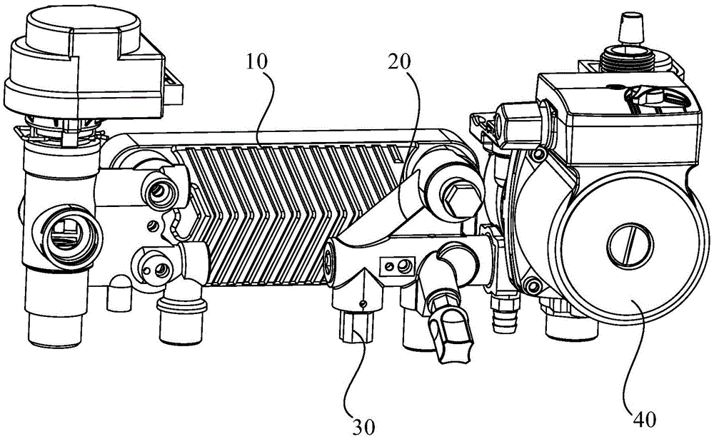
图1为本实用新型壁挂炉一实施例的局部结构示意图;Fig. 1 is the partial structure schematic diagram of an embodiment of the utility model wall-hung boiler;
图2为图1中进水阀和流量调节阀的结构示意图;Fig. 2 is the structural representation of the water inlet valve and the flow regulating valve in Fig. 1;
图3为图1中进水阀和流量调节阀的内部结构示意图;Figure 3 is a schematic diagram of the internal structure of the water inlet valve and the flow regulating valve in Figure 1;
图4为图1中进水阀和流量调节阀的另一结构示意图;Fig. 4 is another structural representation of the water inlet valve and the flow regulating valve in Fig. 1;
图5为图1中进水阀和流量调节阀的又一结构示意图;Fig. 5 is another structural schematic diagram of the water inlet valve and the flow regulating valve in Fig. 1;
图6为图1中流量调节阀的结构示意图。FIG. 6 is a schematic structural diagram of the flow regulating valve in FIG. 1 .
附图标号说明:Description of reference numbers:


本实用新型目的的实现、功能特点及优点将结合实施例,参照附图做进一步说明。The realization, functional characteristics and advantages of the purpose of the present utility model will be further described with reference to the accompanying drawings in conjunction with the embodiments.
具体实施方式Detailed ways
下面将结合本实用新型实施例中的附图,对本实用新型实施例中的技术方案进行清楚、完整地描述,显然,所描述的实施例仅仅是本实用新型的一部分实施例,而不是全部的实施例。基于本实用新型中的实施例,本领域普通技术人员在没有作出创造性劳动前提下所获得的所有其他实施例,都属于本实用新型保护的范围。The technical solutions in the embodiments of the present utility model will be clearly and completely described below with reference to the accompanying drawings in the embodiments of the present utility model. Obviously, the described embodiments are only a part of the embodiments of the present utility model, not all of them. Example. Based on the embodiments of the present invention, all other embodiments obtained by those of ordinary skill in the art without creative work fall within the protection scope of the present invention.
需要说明,若本实用新型实施例中有涉及方向性指示(诸如上、下、左、右、前、后……),则该方向性指示仅用于解释在某一特定姿态(如附图所示)下各部件之间的相对位置关系、运动情况等,如果该特定姿态发生改变时,则该方向性指示也相应地随之改变。It should be noted that if there are directional indications (such as up, down, left, right, front, back, etc.) in the embodiments of the present invention, the directional indications are only used to explain a certain posture (such as the accompanying drawings). When the relative positional relationship, movement situation, etc. between the various components shown below), if the specific posture changes, the directional indication also changes accordingly.
另外,若本实用新型实施例中有涉及“第一”、“第二”等的描述,则该“第一”、“第二”等的描述仅用于描述目的,而不能理解为指示或暗示其相对重要性或者隐含指明所指示的技术特征的数量。由此,限定有“第一”、“第二”的特征可以明示或者隐含地包括至少一个该特征。另外,全文中出现的“和/或”的含义为,包括三个并列的方案,以“A和/或B”为例,包括A方案,或B方案,或A和B同时满足的方案。另外,各个实施例之间的技术方案可以相互结合,但是必须是以本领域普通技术人员能够实现为基础,当技术方案的结合出现相互矛盾或无法实现时应当认为这种技术方案的结合不存在,也不在本实用新型要求的保护范围之内。In addition, if there are descriptions involving "first", "second", etc. in the embodiments of the present invention, the descriptions of "first", "second", etc. are only for the purpose of description, and should not be construed as instructions or Implicit their relative importance or implicitly indicate the number of technical features indicated. Thus, a feature delimited with "first", "second" may expressly or implicitly include at least one of that feature. In addition, the meaning of "and/or" in the whole text is to include three parallel schemes. Taking "A and/or B" as an example, it includes scheme A, scheme B, or scheme that A and B satisfy at the same time. In addition, the technical solutions between the various embodiments can be combined with each other, but must be based on the realization by those of ordinary skill in the art. When the combination of technical solutions is contradictory or cannot be realized, it should be considered that the combination of such technical solutions does not exist. , is not within the scope of protection required by the present utility model.
本实用新型提出一种壁挂炉,该壁挂炉既能够提供为室内供暖的采暖水,又能够提供卫浴热水。该壁挂炉包括换热器10、进水阀20和水泵40。进水阀20设有依次连通的卫浴水进口21、卫浴水通道23和卫浴水出口22,以及依次连通的采暖水进口24、采暖水通道26和采暖水出口25。其中,卫浴水出口22、采暖水进口24与换热器10连通,采暖水出口25与水泵40的进水端连通。具体而言,自来水经卫浴水进口21进入卫浴通道后,由卫浴水出口22进入换热器10;同时,由于水泵40的作用,采暖水流经换热器10,再经采暖水进口24进入采暖水通道26,从采暖水出口25进入水泵40。如此,低温的卫浴水和高温的采暖水在换热器10里进行换热,从而实现加热卫浴水的目的。The utility model proposes a wall-hung boiler, which can not only provide heating water for indoor heating, but also provide hot water for bathroom. The wall-hung boiler includes a
参照图1至图4所示,在本实用新型一实施例中,所述壁挂炉包括:1 to 4, in an embodiment of the present invention, the wall-hung boiler includes:
换热器10;
进水阀20,所述进水阀20设有卫浴水进口21、卫浴水出口22和连通所述卫浴水进口21、所述卫浴水出口22的卫浴水通道23,所述卫浴水出口22与所述换热器10连通;A
流量调节阀30,所述流量调节阀30设置于所述卫浴水进口21、所述卫浴水出口22和所述卫浴水通道23中的任意一处。The
应说明的是,所述流量调节阀30可以为手动阀、电磁阀或者水比例阀等,本实用新型不对流量调节阀30的类型作限定。另外,流量调节阀30可以安装在卫浴水进口21、卫浴水出口22或者卫浴水通道23,本实用新型不对其具体的安装位置进行限定,只要能够实现对从进水阀20进入换热器10的卫浴水流量进行调节即可。It should be noted that the
另需说明的是,现有的壁挂炉不能对进入换热器的卫浴水流量进行调节。虽然可以通过控制壁挂炉的功率,来对卫浴水出水温度进行调节。但壁挂炉的功率限于一定的范围值,当达到最大功率时,卫浴水出水温度可能还低于用户所需温度(比如处于寒冷的冬季时);当到达最小功率时,卫浴水出水温度可能还高于用户所需温度(比如处于闷热的夏季时)。为了使冬天的卫浴水温度能够满足用户的需求,现有的壁挂炉往往通过在进水阀的卫浴水通道里面设置限流环,以降低换热器中卫浴水的流量,从而使得在冬季时卫浴水出水温度比较高,但当处于夏季时用户往往不需要过高的卫浴水温度,此时壁挂炉就存在卫浴水温度过高的问题。It should also be noted that the existing wall-hung boiler cannot adjust the flow rate of sanitary water entering the heat exchanger. Although the temperature of the bathroom water outlet can be adjusted by controlling the power of the wall-hung boiler. However, the power of the wall-hung boiler is limited to a certain range value. When the maximum power is reached, the temperature of the bathroom water outlet may be lower than the temperature required by the user (such as in cold winter); when the minimum power is reached, the bathroom water outlet temperature may still be Higher than the user's desired temperature (such as during a hot summer day). In order to make the temperature of the bathroom water in winter meet the needs of users, the existing wall-hung boilers often reduce the flow of bathroom water in the heat exchanger by setting a restrictor ring in the bathroom water channel of the water inlet valve, so that in winter The outlet water temperature of the bathroom water is relatively high, but when it is in summer, users often do not need a high bathroom water temperature. At this time, the wall-hung boiler has the problem that the bathroom water temperature is too high.
而本实用新型技术方案,通过在进水阀20上设置流量调节阀30来调节进入换热器10中的卫浴水流量,能够使卫浴水出水温度满足不同季节的温度需求。可以理解,在换热器10中采暖水的温度恒定的情况下,换热器10中的卫浴水流量会影响卫浴水出水温度。当换热器10中的卫浴水较少时,同样温度的采暖水使卫浴水温升较大,当换热器10中的卫浴水较多时,同样温度的采暖水就会使卫浴水温升较小。因此,在冬季时,通过流量调节阀30减小进入换热器10中的卫浴水流量,能够调高卫浴水的出水温度;而在夏季时,通过流量调节阀30增大进入换热器10中的卫浴水流量,能够调低卫浴水的出水温度。In the technical solution of the present invention, the
在一实施例中,请一并参照图5所示,流量调节阀30设置于卫浴水通道23,流量调节阀30包括相互连接的手柄31和阀芯32,阀芯32开设有出水孔及多个进水孔,至少部分进水孔的进水面积不同,出水孔与卫浴水通道23连通,手柄31用以驱动阀芯32移动,以切换不同进水面积的进水孔与卫浴水通道23进行连通。可以理解,本实施例中,流量调节阀30采用手动阀,当用户需要较高的卫浴水出水温度时,通过移动手柄31,从而驱动阀芯32移动,切换较小面积的进水孔与卫浴水通道23连通,以减小从进水阀20进入换热器10的卫浴水流量,从而使得卫浴水出水温度较高;相反地,当用户需要较低的卫浴水出水温度时,通过移动手柄31,驱动阀芯32移动,切换较大面积的进水孔与卫浴水通道23连通,以增大从进水阀20进入换热器10的卫浴水流量,从而使得卫浴水出水温度较低。当然,在其它实施例中,流量调节阀30可以采用电磁阀、水比例阀等,其中,水比例阀具有可调节流量大小的流量间隙,通过调节流量间隙的大小,就可以调节进水阀20中卫浴水流量的大小。In one embodiment, please refer to FIG. 5 together, the
进一步地,多个进水孔沿阀芯32的周向分布,手柄31用以驱动阀芯32旋转,以切换不同进水面积的进水孔与卫浴水通道23进行连通。具体而言,该阀芯32为中通的环形结构,多个进水孔沿其周向分布,因此,通过旋转手柄31带动阀芯32旋转,即可切换不同进水面积的进水孔与卫浴水通道23进行连通。当然,可以在壁挂炉的外壳上设置相应的流量调节开关,该流量调节开关与手柄31连接,该流量调节开关上可标识流量级别,用户可通过旋转该流量调节开关,来带动手柄31及阀芯32旋转,以提高用户操作的便捷性。Further, a plurality of water inlet holes are distributed along the circumference of the
进一步地,多个不同进水面积的进水孔沿阀芯32的周向按进水面积逐渐递增或递减的顺序排布。可以理解,将不同进水面积进水孔按照一定的顺序和规律排布,可以方便用户快速识别流量级别和进行操作。比如,沿顺时针旋转流量调节开关时,就是增大进水阀20中的卫浴水流量,降低卫浴水出水温度;而沿逆时针旋转流量调节开关时,就是减小进水阀20中的卫浴水流量,提高卫浴水出水温度。Further, a plurality of water inlet holes with different water inlet areas are arranged along the circumferential direction of the
在另一实施例中,多个进水孔沿阀芯32的轴向分布,手柄31用以驱动阀芯32伸缩运动,以切换不同进水面积的进水孔与卫浴水通道23进行连通。区别于通过旋转手柄31来旋转阀芯32的方式,本实施例通过推动或拉伸手柄31的方式,同样可以实现切换不同进水面积的进水孔与卫浴水通道23进行连通的目的。In another embodiment, a plurality of water inlet holes are distributed along the axial direction of the
进一步地,多个不同进水面积的进水孔沿阀芯32的轴向按大小逐渐递增或递减的顺序排布。同样地,将不同进水面积进水孔按照一定的顺序和规律排布,可以方便用户快速识别流量级别和进行操作。Further, a plurality of water inlet holes with different water inlet areas are arranged along the axial direction of the
本实施例中,参照图6所示,多个进水孔包括多个第一进水孔321和多个第二进水孔322,第一进水孔321的进水面积大于所述第二进水孔322的进水面积,第一进水孔321和第二进水孔322沿阀芯32的周向排布,且第一进水孔321和第二进水孔322交替间隔排布。如此,用户不管往左旋还右旋,都可以切换不同进水面积的进水孔与卫浴水通道23进行连通,不用用户特意去记忆和识别。当然,本实施例中,进水孔只有两种不同大小的进水面积,也就是只有两档卫浴水进水流量,用户较容易进行区分。在冬季时,通过旋转手柄31,使第二进水孔322与卫浴水通道23连通,降低进入换热器10的卫浴水流量,以提高卫浴出水温度;在夏季时,则切换第一进水孔321与卫浴水通道23连通,提高进入换热器10的卫浴水流量,以降低卫浴水出水温度。In this embodiment, as shown in FIG. 6 , the plurality of water inlet holes include a plurality of first water inlet holes 321 and a plurality of second water inlet holes 322 , and the water inlet area of the first water inlet holes 321 is larger than that of the second water inlet holes 321 . The water inlet area of the
本实施例中,参照图1所示,所述换热器10为板式换热器,板式换热器包括卫浴水流道和采暖水流道。具体的,采暖水流道与进水阀20的采暖水进口24连通,进水阀20的卫浴水出口22与卫浴水流道连通。采暖水从从板式换热器10的一端进入采暖水流道,卫浴水从板式换热器10的另一端进入卫浴水流道,然后低温卫浴水和高温采暖水在板式换热器里进行换热。In this embodiment, as shown in FIG. 1 , the
进一步地,参照图5所示,该壁挂炉还包括流量传感器50、温度探头60和控制器(附图未示),流量传感器50安装于卫浴水通道23处,流量传感器50用以测量卫浴水通道23的水流量。温度探头60设于卫浴水通道23,用于感测卫浴水进水温度。流量传感器50和温度探头60均与控制器电连接,控制器通过卫浴温度探头60和流量传感器50收集的信息,控制壁挂炉的功率。Further, as shown in FIG. 5 , the wall-hung boiler also includes a
进一步地,参照图4和图5所示,该壁挂炉还包括补水阀70,所述补水阀70设于卫浴水通道23和采暖水通道26之间,补水阀70用以控制卫浴水通道23和采暖水通道26的连通和断开。当壁挂炉的采暖水水压偏低时,可以通过打开补水阀70使卫浴水通道23的水流入采暖水通道26以对采暖水通道26进行补水。Further, as shown in FIG. 4 and FIG. 5 , the wall-hung boiler further includes a
以上所述仅为本实用新型的优选实施例,并非因此限制本实用新型的专利范围,凡是在本实用新型的实用新型构思下,利用本实用新型说明书及附图内容所作的等效结构变换,或直接/间接运用在其他相关的技术领域均包括在本实用新型的专利保护范围内。The above are only preferred embodiments of the present utility model, and are not intended to limit the scope of the present utility model patent. Under the concept of the utility model of the present utility model, the equivalent structure transformations made by using the contents of the present utility model description and accompanying drawings, Or directly/indirectly applied in other related technical fields are included in the scope of patent protection of the present invention.
Claims (11)
Priority Applications (1)
| Application Number | Priority Date | Filing Date | Title |
|---|---|---|---|
| CN202020127087.XU CN211695437U (en) | 2020-01-19 | 2020-01-19 | fireplace |
Applications Claiming Priority (1)
| Application Number | Priority Date | Filing Date | Title |
|---|---|---|---|
| CN202020127087.XU CN211695437U (en) | 2020-01-19 | 2020-01-19 | fireplace |
Publications (1)
| Publication Number | Publication Date |
|---|---|
| CN211695437U true CN211695437U (en) | 2020-10-16 |
Family
ID=72773681
Family Applications (1)
| Application Number | Title | Priority Date | Filing Date |
|---|---|---|---|
| CN202020127087.XU Active CN211695437U (en) | 2020-01-19 | 2020-01-19 | fireplace |
Country Status (1)
| Country | Link |
|---|---|
| CN (1) | CN211695437U (en) |
-
2020
- 2020-01-19 CN CN202020127087.XU patent/CN211695437U/en active Active
Similar Documents
| Publication | Publication Date | Title |
|---|---|---|
| CN205002407U (en) | Constant -temperature gas water heater | |
| CN111043640B (en) | A heating system and its control method | |
| US20200080788A1 (en) | Multi-coil heat exchanger | |
| CN110686410A (en) | Intelligent water mixing system for gas water heater and control method thereof | |
| CN110094882A (en) | Gas heater and control method, computer readable storage medium, heating system | |
| CN211695437U (en) | fireplace | |
| WO2021012832A1 (en) | Heating and hot-water apparatus and control method therefor | |
| CN111102741A (en) | Zero-cold-water preheating wall-mounted boiler system with pre-heating function and simultaneous use function | |
| CN211345824U (en) | Gas wall-mounted boiler system with independent temperature-adjusting water faucet | |
| CN211290527U (en) | Wall-mounted furnace | |
| CN204438540U (en) | The thermostatically-controlled equipment of electric water heater system and electric heater | |
| CN111102740A (en) | Wall-mounted furnace system capable of being used for heating and bathing simultaneously | |
| CN110749092A (en) | Gas wall-mounted furnace system with different water supply terminal temperatures | |
| CN210624878U (en) | Sleeve type wall-mounted furnace | |
| CN211400281U (en) | Wall-mounted furnace | |
| CN211345809U (en) | Gas water heater system with independent temperature-adjusting faucet | |
| CN207881192U (en) | Gas heater and heating system | |
| CN211233348U (en) | a wall-hung furnace | |
| CN111306781B (en) | Wall-mounted boiler | |
| CN209605249U (en) | Heating and hot water installations and heating and hot water systems | |
| CN211503220U (en) | Water heating stove | |
| CN223649467U (en) | A gas-fired wall-hung boiler | |
| CN211204401U (en) | Wall-mounted stove | |
| CN212057730U (en) | Wall-mounted furnace system capable of being used for heating and bathing simultaneously | |
| CN211345827U (en) | Gas wall-mounted furnace system with different water supply terminal temperatures |
Legal Events
| Date | Code | Title | Description |
|---|---|---|---|
| GR01 | Patent grant | ||
| GR01 | Patent grant |