CN211892425U - Three-color printing machine for adhesive tape printing - Google Patents
Three-color printing machine for adhesive tape printing Download PDFInfo
- Publication number
- CN211892425U CN211892425U CN202020143613.1U CN202020143613U CN211892425U CN 211892425 U CN211892425 U CN 211892425U CN 202020143613 U CN202020143613 U CN 202020143613U CN 211892425 U CN211892425 U CN 211892425U
- Authority
- CN
- China
- Prior art keywords
- roller
- printing
- frame
- power
- adhesive tape
- Prior art date
- Legal status (The legal status is an assumption and is not a legal conclusion. Google has not performed a legal analysis and makes no representation as to the accuracy of the status listed.)
- Active
Links
- 238000007639 printing Methods 0.000 title claims abstract description 152
- 239000002390 adhesive tape Substances 0.000 title claims description 92
- 230000007246 mechanism Effects 0.000 claims abstract description 100
- 238000004804 winding Methods 0.000 claims abstract description 71
- 238000012546 transfer Methods 0.000 claims abstract description 27
- 238000001035 drying Methods 0.000 claims abstract description 26
- 238000007599 discharging Methods 0.000 claims abstract description 15
- 230000008859 change Effects 0.000 claims abstract description 6
- 230000005540 biological transmission Effects 0.000 claims description 43
- 238000004049 embossing Methods 0.000 claims description 31
- 238000005485 electric heating Methods 0.000 claims description 21
- 238000006243 chemical reaction Methods 0.000 claims description 12
- 230000008878 coupling Effects 0.000 claims description 10
- 238000010168 coupling process Methods 0.000 claims description 10
- 238000005859 coupling reaction Methods 0.000 claims description 10
- 238000012423 maintenance Methods 0.000 claims description 6
- 238000003825 pressing Methods 0.000 claims description 3
- 239000000853 adhesive Substances 0.000 claims 2
- 230000001070 adhesive effect Effects 0.000 claims 2
- 238000004891 communication Methods 0.000 claims 1
- 238000005520 cutting process Methods 0.000 abstract description 18
- 239000003086 colorant Substances 0.000 description 10
- 238000005096 rolling process Methods 0.000 description 9
- 238000007664 blowing Methods 0.000 description 6
- 238000010073 coating (rubber) Methods 0.000 description 6
- 230000007306 turnover Effects 0.000 description 6
- 238000000034 method Methods 0.000 description 5
- 239000006247 magnetic powder Substances 0.000 description 4
- 239000000049 pigment Substances 0.000 description 4
- 230000001360 synchronised effect Effects 0.000 description 4
- 229920000297 Rayon Polymers 0.000 description 2
- 238000004026 adhesive bonding Methods 0.000 description 2
- 230000008901 benefit Effects 0.000 description 2
- 239000011127 biaxially oriented polypropylene Substances 0.000 description 2
- 229920006378 biaxially oriented polypropylene Polymers 0.000 description 2
- 238000010276 construction Methods 0.000 description 2
- 238000010586 diagram Methods 0.000 description 2
- 238000005516 engineering process Methods 0.000 description 2
- 230000008569 process Effects 0.000 description 2
- 239000000523 sample Substances 0.000 description 2
- 239000011265 semifinished product Substances 0.000 description 2
- 238000002791 soaking Methods 0.000 description 2
- 230000004075 alteration Effects 0.000 description 1
- 230000000052 comparative effect Effects 0.000 description 1
- 239000003292 glue Substances 0.000 description 1
- 238000007646 gravure printing Methods 0.000 description 1
- 238000004519 manufacturing process Methods 0.000 description 1
- 238000012986 modification Methods 0.000 description 1
- 230000004048 modification Effects 0.000 description 1
- 238000007645 offset printing Methods 0.000 description 1
- 238000003860 storage Methods 0.000 description 1
- 238000006467 substitution reaction Methods 0.000 description 1
- 238000012360 testing method Methods 0.000 description 1
Images





Landscapes
- Rotary Presses (AREA)
Abstract
The utility model discloses a three-colour printing machine for sticky tape printing, including chassis, frame, air pump and power unit, the fixed workstation that is provided with in top of chassis, power unit fix in one side of frame, wherein, are provided with winding mechanism, cutting mechanism in the frame, and supporting mechanism, drying mechanism, power unit and printing mechanism, the frame is fixed in one side of workstation, is provided with the base on the workstation, and one side of base is fixed and is provided with the stand. The printing mechanism comprises a printing center roller, a discharging roller and a plurality of printing groups; each printing group comprises a raised printing roller, an ink groove, a transfer roller, a bracket and a transverse moving frame, wherein two printing groups are arranged on one side of a printing center roller, and one printing group is arranged on the other side of the printing center roller. The utility model discloses simple structure, convenient to use adopt relief printing, and the printing plate expense is low, and the customer can be random change printing plate, and is time-saving swift, and the volume of ordering is little, and is with low costs, and the specially adapted printing plate is changed soon, uses small in quantity's customer's demand.
Description
Technical Field
The utility model relates to a printing machine technical field, concretely relates to three-colour printing machine is used in sticky tape printing.
Background
A three-color printer for printing adhesive tape is a printing device for printing trademarks, characters and the like on adhesive tape blanks, and for the existing adhesive tape printing in China, the three-color printer is a process of firstly carrying out color printing on a BOPP film, then carrying out gluing to form a large roll, and then cutting the large roll into small rolls. However, the process has the disadvantages of complex manufacturing process, long construction period, large subscription amount and high cost. With the progress of the technology, the technology of firstly gluing the BOPP film and then printing on the viscose surface is available in the market, and the advantage of printing on the viscose surface is as follows: no matter how rubbed the tape, the printed words are not damaged. But still has the problems of long construction period, large volume of orders and high cost. Both the two modes adopt a gravure printing mode, and the plate replacement is not easy.
In view of the fact that the market demands for tape printing mostly tend to small-batch, personalized customization, such as the order of 10-20 rolls, and frequent replacement of the printed patterns or marks on the tape, the above two conventional intaglio printing methods have the problems of large order and high cost. Therefore, it is necessary to improve the technical problem and provide a three-color printing machine for offset printing, which has the advantages of simple structure, convenient use, relief printing, low printing plate cost, free printing plate replacement by customers, time saving, rapidness, small order making amount, low cost, quick plate replacement, and small use amount.
Disclosure of Invention
Technical problem to be solved
The utility model provides a simple structure, convenient to use adopt relief printing, and the printing plate expense is low, and the customer can be random change the printing plate, and is swift in a time-saving way, and the volume of ordering is little, and is with low costs, and specially adapted printing plate changes soon, uses a three-colour printing machine for the adhesive tape printing of small in quantity's customer's demand.
(II) technical scheme
Adopt relief printing for realizing above-mentioned simple structure, convenient to use, the printing plate expense is low, and the change printing plate that the customer can be random, and is time-saving swift, and the volume of ordering is little, and is with low costs, and the specially adapted printing plate is changed soon, uses the purpose of the customer's demand of small in quantity, the utility model provides a following technical scheme:
the utility model discloses three-colour printing machine is used in sticky tape printing, including the chassis, a machine support, air pump and power unit, the fixed workstation that is provided with in top of chassis, power unit fixes the one side in the frame, is provided with motor power and power conversion wheel on the power unit, is provided with belt pulley and master gear on the motor power output shaft, wherein, is provided with winding mechanism in the frame, cuts the mechanism, supporting mechanism, stoving mechanism, power unit and printing mechanism, one side at the workstation is fixed to the frame, is provided with the base on the workstation, the fixed stand that is provided with in one side of base.
Further, the printing mechanism comprises a printing center roller, a discharging roller and a plurality of printing groups; each printing group comprises a raised printing roller, an ink tank, a transfer roller, a bracket and a transverse moving frame, a printing center roller is connected between a power mechanism and the upright post through a shaft, a belt wheel on an output shaft of a power motor is in belt transmission with a power conversion wheel, one section of the printing center roller stretching into the power mechanism is in belt transmission connection with the power conversion wheel, and a transmission gear is fixedly arranged on the section of the printing center roller exposed out of the frame.
Furthermore, two printing groups are arranged on one side of the printing center roller, one printing group is arranged on the other side of the printing center roller, an ink tank is fixed on the transverse moving frame, a support is fixed at the front end of the ink tank, a raised printing roller is connected to the support in an upper shaft mode, a bracket is arranged beside the support and suspended above the ink tank, the bracket is respectively connected with an ink roller and a transfer roller in a shaft mode from bottom to top, the transfer roller is tangent to the ink roller, and the ink roller is partially immersed in the ink tank; the transverse moving frame is connected to the upright post through a screw structure, the tail end of the transverse moving frame is provided with a relief printing roller adjusting handle, the thread adjusting of the relief printing roller adjusting handle is used for adjusting the distance between a relief printing roller and a printing center roller, the bracket is connected with the ink tank in a sliding mode, the bracket is connected with the bracket adjusting handle through the screw structure, the thread adjusting of the bracket adjusting handle is used for adjusting the distance between a transfer roller and the relief printing roller, and the ink roller, the transfer roller and the relief printing roller are connected with the transmission teeth of the printing center roller in a meshing mode.
Further, the carriage is a rectangular plate with a slope, and the slope is arranged to facilitate the assembly of an ink roller or a transfer roller.
Furthermore, a temperature adjusting button of the drying mechanism is arranged on the upper side of the rack, one side of an electric heating tube of the drying mechanism is inserted into the temperature control probe, and the temperature of the electric heating tube is adjusted through the temperature adjusting button.
Further, the upside of frame is provided with air pump control switch (blowing switch for opening or closing of control inflatable axle, conveniently inserts the wide sticky tape blank of large-width on the blowing roller), and the upside of frame is provided with the upset control switch for the switching of two rolling turnplates of control winding mechanism.
Further, the winding mechanism includes rolling capstan a, rolling capstan b, the upset motor, tilting mechanism, frame plate and shaft coupling, the winding mechanism is located the opposite side of frame, rolling capstan a, rolling capstan b is connected with the frame hub connection, the rear side of frame is provided with the maintenance door, fixed connection between frame plate and the frame, rolling capstan a, rolling capstan b upper shaft coupling has the adhesive tape roller, the epaxial embedding of adhesive tape roller has the stretching lug, be provided with two gear trains on the frame plate, every gear train is the multilayer tooth structure, the meshing is connected between one deck tooth wherein of gear train and the corresponding adhesive tape roller, power unit drives two adhesive tape rollers of this group of one of gear train meshing through chain drive and rotates.
Furthermore, power unit includes power motor, main power embossing roll, auxiliary drive embossing roll and power conversion wheel, and the top of printing center roller is provided with drying mechanism, and one side of drying mechanism is provided with the main power embossing roll, and the opposite side is provided with auxiliary drive embossing roll, and the main power embossing roll is connected with the hub connection between frame, and the main power embossing roll passes through chain drive between auxiliary drive embossing roll and the main gear of power motor output shaft, and the chain further transmits power to corresponding adhesive tape roller on the rolling mechanism.
Furthermore, the supporting mechanism comprises a supporting roller a and a supporting roller b, the supporting roller a and the supporting roller b are connected with the rack shaft, the supporting roller a is located on the left side of the auxiliary driving printing roller, the supporting roller b is located on the right side of the auxiliary driving printing roller, a guide roller is arranged between the printing center roller and the main driving force printing roller, and the guide roller is connected with the rack shaft.
Furthermore, the power of the power motor, the turnover motor, the drying system and the like is electrically connected with an external power supply.
Further, the drying mechanism comprises a fan, an electric heating tube, a cover plate and a bottom plate, the bottom plate is fixedly connected with the rack, the cover plate is located right above the bottom plate and is connected with the upper portion of the rack through hinges, a plurality of holes are formed in the cover plate, the fan is installed in the holes, a plurality of electric heating tubes are fixedly installed on the cover plate, the fan is located above the electric heating tubes, and the distance between the electric heating tubes and the bottom plate is 2-5 cm.
Furthermore, a cutting mechanism is fixed right above the middle point of the connecting line of the main power embossing roll and the auxiliary transmission embossing roll, the cutting mechanism comprises a plurality of adjusting handles, a plurality of cutting knives and a rubber coating roll, the cutting knives are fixed at the tail end of the adjusting handles, the adjusting handles are used for adjusting the pressing angles of the cutting knives, and the knife tips of the cutting knives press the side of the rubber coating roll.
Further, an air expansion shaft is wrapped on the outer wall of the discharging roller, the air pump is in pneumatic connection with the air expansion shaft, and the air pump is used for expanding the air expansion shaft pneumatically so as to tightly fix the adhesive tape blank with large width on the discharging roller; the turnover motor drives the winding rotary disc a and the winding rotary disc b to replace through another layer of teeth of the coupling transmission chain meshing gear set according to a manual control turnover switch, so that the winding rotary disc a is driven, and the meshing relation between the adhesive tape roller on the winding rotary disc b and the transmission chain of the power mechanism is realized, and then the operation of changing the adhesive tape roll is realized.
For better realization the utility model discloses the purpose, the utility model discloses again provides the use of three-colour printing machine for the sticky tape printing, wherein: the method comprises the following steps:
A. assembling the adhesive tape blank: sleeving the large-width adhesive tape blank on a discharging roller, and expanding an air expansion shaft by an air pump to tightly fix the blank on the discharging roller; the paper roll with the size to be cut is sleeved on the stretching convex sheet of the adhesive tape roll, the adhesive tape withdrawn from the large-width adhesive tape blank is wound to the printing center roll along the guide roll, and then is wound to the main power printing roll, so that the adhesive tape is suspended above the bottom plate and then is transmitted to the supporting roll b, the auxiliary transmission printing roll, the supporting roll a and the rubber coating roll, and then the small-width adhesive tape cut by the slitting knife is wound on the paper roll on the corresponding adhesive tape roll,
B. a step of setting a printing mechanism: matching three colors according to the customer identification, and filling pigments into corresponding ink tanks; installing relief printing rollers corresponding to the corresponding pigments, printing a relief printing plate with a color tone on each relief printing roller according to the principle of three-color printing, assembling the relief printing rollers with the corresponding colors on a bracket, partially soaking an ink roller into an ink tank with the corresponding colors, transferring the corresponding colors to a transfer roller by the ink roller, printing the corresponding colors on the rubber surface of a printing center roller by the transfer roller,
C. adjusting the drying mechanism: adjusting the drying temperature, adjusting the distance between the adhesive tape and the electric heating tube, and adjusting the wind speed and the wind quantity of the fan for blowing air to the adhesive tape to transfer the heat of the electric heating tube to the adhesive tape;
D. adjusting the tightness of the adhesive tape and changing the roll: a magnetic powder clutch can be arranged on the winding mechanism to control the tension of the adhesive tape, the overturning motor is meshed with the other layer of teeth of the gear set through a coupling transmission chain, and the winding rotary disc a and the winding rotary disc b are driven to replace according to the manual control of an overturning switch, so that the meshing relation between an adhesive tape roller on the winding rotary disc a and the winding rotary disc b and a transmission chain of a power mechanism is realized, and the operation of changing the adhesive tape is further realized;
E. slitting: after the adhesive tape passes through the slitting mechanism, the slitting knife divides the transferred large-width blank into small widths, the small-width adhesive tape is transferred to a corresponding winding rotary disc a through a rubber coating roller, and a paper roll on the adhesive tape roller is arranged on a winding rotary disc b to complete synchronous printing and synchronous slitting
Compared with the prior art, the utility model discloses simple structure, convenient to use adopt relief printing, and the printing plate expense is low, and the change printing plate that the customer can be random, and it is swift to save time, and the volume of ordering is little, and is with low costs, and the specially adapted printing plate is changed soon, uses the purpose of the few customer's demand of quantity: the utility model firstly puts the semi-finished product of the adhesive tape (large-width adhesive tape blank) on the air expansion shaft of the discharging roller. The adhesive tape is supported by an adjustable guide roller, a printing center roller, a supporting roller and other guide wheels to reach certain tension, a semi-finished adhesive tape is cut into adhesive tapes with required specification and width by a cutting mechanism, then the adhesive tapes with required code length are automatically wound by a winding mechanism, the winding mechanism can automatically exchange two winding shafts, after the winding shafts are replaced, the films are manually cut off, the wound adhesive tapes are dismounted, and the other winding shaft which is exchanged performs working winding. Tape printing is accomplished by three sets of printing mechanisms around a print center roll. The ink roller is stained with ink in the ink tank, the ink is transferred to the relief printing roller through the transfer roller, and the relief printing roller is printed on the adhesive tape on the printing center roller, so that the adhesive tape is colored. The colored adhesive tape is dried by a drying mechanism and then cut into adhesive tapes of the specifications required by customers by a cutting mechanism. The transmission of the equipment is realized by driving a belt pulley by a driving motor, driving a chain wheel of a corresponding main transmission embossing roller, a printing center roller and the like by a main gear and a winding chain wheel (gear group), and the winding transmission is provided with a magnetic powder clutch to further control the tension.
Drawings
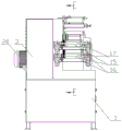
Fig. 1 is a schematic structural view in the main view direction of the present invention;
fig. 2 is a schematic structural view of the rear view direction of the present invention;
FIG. 3 is a schematic structural view in the left-view direction of the present invention;
FIG. 4 is a schematic structural view in the right-viewing direction of the present invention;
FIG. 5 is a schematic cross-sectional view of the location F-F in FIG. 1;
fig. 6 is a schematic structural diagram of the rear view direction (the transmission relationship is shown after the maintenance door is opened) of the present invention.
Fig. 7 is a schematic view of the top view of the present invention.
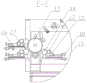
Fig. 8 is a schematic cross-sectional view taken along the direction E-E in fig. 3.
Fig. 9 is a perspective view of the present invention.
Reference symbols of the drawings
1. Underframe 2, storage cabinet 3, frame
4. Winding mechanism 4a, winding turnplate a 4b, winding turnplate b
5. Adhesive tape roller 5a, stretching lug 6 and rubber covered roller
7. Slitting mechanism 7a, adjusting handle 7b and slitting knife
8. Support mechanism 8a, support roller a 8b, support roller b
9a, a main drive embossing roller 9b, an auxiliary drive embossing roller 10 and a discharge roller
10a, an air expansion shaft 11, a drying mechanism 11a and a fan
11b, an electric heating tube 11c, a cover plate 11d, and a bottom plate
12. Guide roller 13, printing center roller 14, relief roller
15. Ink roller 16, ink tank 17, transfer roller
18. Bracket adjusting handle 19, relief roller adjusting handle 20 and power motor
21. Maintenance door 22, turnover mechanism 23 and turnover motor
24. Coupling 25, frame plate 26, sideslip frame
27. Bracket 28, power conversion wheel 29 and power mechanism
30. Workbench 31, base 32 and upright post
Detailed Description
The technical solutions in the embodiments of the present invention will be described clearly and completely with reference to the accompanying drawings in the embodiments of the present invention, and it is obvious that the described embodiments are only some embodiments of the present invention, not all embodiments. Based on the embodiments in the present invention, all other embodiments obtained by a person skilled in the art without creative work belong to the protection scope of the present invention.
Referring to fig. 1-9, fig. 1 is a schematic structural view in the main view direction of the present invention; fig. 2 is a schematic structural view of the rear view direction of the present invention; FIG. 3 is a schematic structural view in the left-view direction of the present invention; FIG. 4 is a schematic structural view in the right-viewing direction of the present invention; FIG. 5 is a schematic cross-sectional view of the location F-F in FIG. 1; fig. 6 is a schematic structural diagram of the rear view direction (the transmission relationship is shown after the maintenance door is opened) of the present invention. Fig. 7 is a schematic view of the top view of the present invention. Fig. 8 is a schematic cross-sectional view taken along the direction E-E in fig. 3. Fig. 9 is a perspective view of the present invention.
The utility model discloses three-colour printing machine is used in sticky tape printing, including chassis 1, frame 3, air pump and power unit 29, the fixed workstation 30 that is provided with in top of chassis 1, one side in frame 3 is fixed to power unit 29, be provided with motor power 20 and power conversion wheel 28 on the power unit 29, be provided with belt pulley and master gear on the motor power 20 output shaft, wherein, be provided with winding mechanism 4 in the frame 3, cut mechanism 7, supporting mechanism 8, drying mechanism 11, power unit 29 and printing mechanism, one side at workstation 30 is fixed to frame 3, be provided with base 31 on the workstation 30, the fixed stand 32 that is provided with in one side of base 31.
Further, the printing mechanism includes a printing center roller 13, a discharging roller 10 and a plurality of printing groups; each printing group comprises a raised plate roller 14, an ink roller 15, an ink tank 16, a transfer roller 17, a bracket 27 and a transverse frame 26, a printing center roller 13 is connected between a power mechanism 29 and a vertical column 32 through a shaft, a belt wheel on an output shaft of a power motor 20 is in belt transmission with a power conversion wheel 28, one section of the printing center roller extending into the power mechanism 29 is in belt transmission connection with the power conversion wheel 28, and a transmission gear is fixedly arranged on the section of the printing center roller exposed out of the frame 3.
Furthermore, two printing groups are arranged on one side of the printing center roller 13, one printing group is arranged on the other side of the printing center roller, an ink tank 16 is fixed on the transverse moving frame 26, a bracket is fixed at the front end of the ink tank 16, a raised plate roller 14 is axially connected to the bracket, a bracket 27 is arranged beside the bracket, the bracket 27 is suspended above the ink tank 16, an ink roller 15 and a transfer roller 17 are respectively axially connected to the bracket 27 from bottom to top, the transfer roller 17 is tangent to the ink roller 15, and the ink roller 15 is partially immersed in the ink tank 16; the transverse frame 26 is connected to the upright column 32 through a screw structure, the tail end of the transverse frame 26 is provided with a relief roller adjusting handle 19, the thread adjustment of the relief roller adjusting handle 19 is used for adjusting the distance between the relief roller 14 and the printing center roller 13, the bracket 27 is in sliding connection with the ink tank 16, the bracket 27 is connected with a bracket adjusting handle 18 through a screw structure, the thread adjustment of the bracket adjusting handle 18 is used for adjusting the distance between the transfer roller 17 and the relief roller 14, and the ink roller 15, the transfer roller 17 and the relief roller 14 are in meshed connection with the driving teeth of the printing center roller 13.
Further, the carriage 27 is a rectangular plate with a slope provided to facilitate the assembly of an ink roller or a transfer roller.
Furthermore, a temperature adjusting button of the drying mechanism is arranged on the upper side of the rack, one side of an electric heating tube of the drying mechanism is inserted into the temperature control probe, and the temperature of the electric heating tube is adjusted through the temperature adjusting button.
Further, the upside of frame is provided with air pump control switch (blowing switch for opening or closing of control inflatable axle, conveniently inserts the wide sticky tape blank of large-width on the blowing roller), and the upside of frame is provided with the upset control switch for the switching of two rolling turnplates of control winding mechanism.
Further, winding mechanism 4 includes winding carousel a4a, winding carousel b4b, turnover motor 23, tilting mechanism 22, frame plate 25 and shaft coupling 24, winding mechanism 4 is located the opposite side of frame 3, winding carousel a4a, winding carousel b4b is connected with frame 3 hub connection, the rear side of frame 3 is provided with maintenance door 21, fixed connection between frame plate 25 and the frame 3, winding carousel a4a, winding carousel b4b upper shaft connection has adhesive tape roller 5, the epaxial embedding of adhesive tape roller 5 props up lug 5a, be provided with two gear trains on the frame plate 25, every gear train is the multilayer tooth structure, meshing connection between one deck tooth of gear train and corresponding adhesive tape roller 5, power unit 29 drives one of them gear train meshing this group of two adhesive tape rollers 5 through chain drive and rotates.
Further, the power mechanism 29 comprises a power motor 20, a main power embossing roller 9a, an auxiliary transmission embossing roller 9b and a power conversion wheel 28, a drying mechanism 11 is arranged above the printing center roller 13, the main power embossing roller 9a is arranged on one side of the drying mechanism, the auxiliary transmission embossing roller 9b is arranged on the other side of the drying mechanism, the main power embossing roller 9a, the auxiliary transmission embossing roller 9b is connected with a shaft between the frames, the main power embossing roller 9a, the auxiliary transmission embossing roller 9b and a main gear of an output shaft of the power motor 20 are in chain transmission, and the chains further transmit power to corresponding adhesive tape rollers 5 on the winding mechanism 4.
Further, the supporting mechanism 8 comprises a supporting roller a and a supporting roller b, the supporting roller a and the supporting roller b are connected with the machine frame 3 through a shaft, the supporting roller a is located on the left side of the auxiliary driving printing roller 9b, the supporting roller b is located on the right side of the auxiliary driving printing roller 9b, a guide roller 12 is arranged between the printing center roller 13 and the main driving printing roller 9a, and the guide roller 12 is connected with the machine frame 3 through a shaft.
Further, the drying mechanism 11 includes a fan 11a, an electric heating tube 11b, a cover plate 11c, and a bottom plate 11d, the bottom plate 11d is fixedly connected with the rack 3, the cover plate 11c is located right above the bottom plate 11d, the cover plate 11c is hinged with the upper portion of the rack 3, a plurality of holes are formed in the cover plate 11c, the fan 11a is installed in the holes, a plurality of electric heating tubes 11b are fixedly installed on the cover plate 11c, the fan 11a is located above the electric heating tube 11b, and a distance of 2-5cm exists between the electric heating tube 11b and the bottom plate 11 d.
Furthermore, a cutting mechanism 7 is fixed right above the middle point of the connecting line of the main power embossing roller 9a and the auxiliary drive embossing roller 9b, the cutting mechanism 7 comprises an adjusting handle 7a, a plurality of cutting knives 7b and a rubber covered roller 6, the cutting knives 7b are fixed at the tail end of the adjusting handle 7a, the adjusting handle 7a is used for adjusting the pressing angle of the cutting knives 7b, and the knife points of the cutting knives 7b are pressed to the side of the rubber covered roller 6.
Further, an air expansion shaft 10a is wound on the outer wall of the discharging roller 10, the air pump is in pneumatic connection with the air expansion shaft 10a, and the air pump is used for expanding the air expansion shaft 10a pneumatically so as to tension and fix the adhesive tape blank with large width on the discharging roller 10; the overturning motor 23 drives the winding rotary disc a4a and the winding rotary disc b4b to replace through another layer of teeth of the coupling transmission chain meshing gear set according to a manual control overturning switch, so that the driving of the winding rotary disc a4a and the meshing relation between the adhesive tape roller 5 on the winding rotary disc b4b and the transmission chain of the power mechanism 29 are realized, and the adhesive tape roll changing operation is further realized.
For better realization the utility model discloses the purpose, the utility model discloses again provides the use of three-colour printing machine for the sticky tape printing, wherein: the method comprises the following steps:
A. assembling the adhesive tape blank: sleeving the large-width adhesive tape blank on a discharging roller, and expanding an air expansion shaft by an air pump to tightly fix the blank on the discharging roller; the paper roll with the size to be cut is sleeved on the stretching convex sheet of the adhesive tape roller 5, the adhesive tape withdrawn from the large-width adhesive tape blank is wound to the printing center roller along the guide roller, and then is wound by the main power printing roller 9a, the adhesive tape is suspended above the bottom plate and then is transmitted to the supporting roller b, the auxiliary transmission printing roller 9b, the supporting roller a and the rubber coating roller 6, and then the small-width adhesive tape cut by the slitting knife is wound on the paper roll on the corresponding adhesive tape roller 5,
B. a step of setting a printing mechanism: matching three colors according to the customer identification, and filling pigments into corresponding ink tanks; installing relief printing rollers corresponding to the corresponding pigments, printing a relief printing plate with a color tone on each relief printing roller according to the principle of three-color printing, assembling the relief printing rollers with the corresponding colors on a bracket, partially soaking an ink roller into an ink tank with the corresponding colors, transferring the corresponding colors to a transfer roller by the ink roller, printing the corresponding colors on the rubber surface of a printing center roller by the transfer roller,
C. adjusting the drying mechanism: adjusting the drying temperature, adjusting the distance between the adhesive tape and the electric heating tube, and adjusting the wind speed and the wind quantity of the fan for blowing air to the adhesive tape to transfer the heat of the electric heating tube to the adhesive tape;
D. adjusting the tightness of the adhesive tape and changing the roll: a magnetic powder clutch can be arranged on the winding mechanism to control the tension of the adhesive tape, the overturning motor 23 is meshed with the other layer of teeth of the gear set through a coupling transmission chain, and the winding rotary disc a4a and the winding rotary disc b4b are replaced by artificially controlling an overturning switch to drive the winding rotary disc a4a and realize the meshing relationship between the adhesive tape roller 5 on the winding rotary disc b4b and the transmission chain of the power mechanism 29, so that the operation of changing the adhesive tape is realized;
E. slitting: after the adhesive tape passes through the slitting mechanism, the slitting knife divides the transferred large-width blank into small-width blanks, the small-width adhesive tape is transferred to the corresponding winding rotary disc a through the rubber coating roller, and the paper roll on the adhesive tape roller 5 is arranged on the winding rotary disc b, so that the steps of synchronous printing and synchronous slitting are completed.
Comparative test:
adopt in the background art to carry out the three-colour printing machine that prints to the face of glue with the utility model discloses do the comparison, relatively as follows:
| group of | Three-color printing on rubber surface | Minimum subscription to order | Printing plate | Cost of | Width mm of blank | Whether to adapt to quick plate changing |
| Background | Can be made into | 2000 roll-up | Intaglio plate | Height of | Fixing | Whether or not |
| The utility model discloses | Can be made into | 10 is rolled up | Relief printing plate | Is low in | 144-288 | Is that |
Compared with the prior art, the utility model discloses simple structure, convenient to use adopt relief printing, and the printing plate expense is low, and the change printing plate that the customer can be random, and it is swift to save time, and the volume of ordering is little, and is with low costs, and the specially adapted printing plate is changed soon, uses the purpose of the few customer's demand of quantity: the utility model firstly puts the semi-finished product of the adhesive tape (large-width adhesive tape blank) on the air expansion shaft of the discharging roller. The adhesive tape is supported by an adjustable guide roller, a printing center roller, a supporting roller and other guide wheels to reach certain tension, a semi-finished adhesive tape is cut into adhesive tapes with required specification and width by a cutting mechanism, then the adhesive tapes with required code length are automatically wound by a winding mechanism, the winding mechanism can automatically exchange two winding shafts, after the winding shafts are replaced, the films are manually cut off, the wound adhesive tapes are dismounted, and the other winding shaft which is exchanged performs working winding. Tape printing is accomplished by three sets of printing mechanisms around a print center roll. The ink roller is stained with ink in the ink tank, the ink is transferred to the relief printing roller through the transfer roller, and the relief printing roller is printed on the adhesive tape on the printing center roller, so that the adhesive tape is colored. The colored adhesive tape is dried by a drying mechanism and then cut into adhesive tapes of the specifications required by customers by a cutting mechanism. The transmission of the equipment is realized by driving a belt pulley by a driving motor, driving a chain wheel of a corresponding main transmission embossing roller, a printing center roller and the like by a main gear and a winding chain wheel (gear group), and the winding transmission is provided with a magnetic powder clutch to further control the tension.
Although embodiments of the present invention have been shown and described, to those of ordinary skill in the art, the practice of the present invention is primarily the three-color printing of the tape, which, based on the structure of the present invention, is modified to two-color printing or six-color printing or even to single-color printing or multi-color printing, using similar structures of the present invention. It is to be understood that various changes, modifications, substitutions and alterations can be made herein without departing from the principles and spirit of the invention, the scope of which is defined by the appended claims and their equivalents, which are also within the scope of the invention as claimed.
Claims (9)
1. The utility model provides a three-colour printing machine is used in sticky tape printing, including chassis (1), frame (3), air pump and power unit (29), the fixed workstation (30) that is provided with in top of chassis (1), one side in frame (3) is fixed in power unit (29), be provided with motor power (20) and power change wheel (28) on power unit (29), be provided with belt pulley and master gear on motor power (20) output shaft, a serial communication port, be provided with winding mechanism (4) on frame (3), cut mechanism (7), supporting mechanism (8), drying mechanism (11), power unit (29) and printing mechanism, frame (3) are fixed in one side of workstation (30), be provided with base (31) on workstation (30), one side of base (31) is fixed and is provided with stand (32).
2. The three-color printing machine for tape printing according to claim 1, wherein the printing mechanism includes a printing center roller (13), a feed roller (10), and a plurality of printing groups; each printing group comprises a raised plate roller (14), an ink roller (15), an ink tank (16), a transfer roller (17), a bracket (27) and a transverse moving frame (26), a printing center roller (13) is connected between a power mechanism (29) and an upright post (32) in a shaft mode, a belt wheel on an output shaft of a power motor (20) is in belt transmission with a power conversion wheel (28), one section of the printing center roller extending into the power mechanism (29) is in belt transmission connection with the power conversion wheel (28), and a transmission tooth is fixedly arranged on one section of the printing center roller exposed out of the rack (3).
3. The three-color printing machine for tape printing according to claim 2, wherein two printing groups are provided on one side of the printing center roller (13), one printing group is provided on the other side, the ink tank (16) is fixed on the traverse frame (26), the front end of the ink tank (16) is fixed with a bracket, the bracket is connected with the gravure roller (14) in an axis manner, a bracket (27) is provided beside the bracket, the bracket (27) is suspended above the ink tank (16), the bracket (27) is respectively connected with the ink roller (15) and the transfer roller (17) in an axis manner from bottom to top, the transfer roller (17) is tangent to the ink roller (15), and the ink roller (15) is partially immersed in the ink tank (16); the transverse moving frame (26) is connected to the upright post (32) through a screw structure, a relief roller adjusting handle (19) is arranged at the tail end of the transverse moving frame (26), the thread adjustment of the relief roller adjusting handle (19) is used for adjusting the distance between the relief roller (14) and the printing center roller (13), the bracket (27) is in sliding connection with the ink tank (16), the bracket adjusting handle (18) is connected to the bracket (27) through the screw structure, the thread adjustment of the bracket adjusting handle (18) is used for adjusting the distance between the transfer roller (17) and the relief roller (14), and the ink roller (15), the transfer roller (17) and the relief roller (14) are in meshing connection with the transmission teeth of the printing center roller (13).
4. The three-color printing machine for printing on adhesive tapes according to any one of claims 1 to 3, wherein the winding mechanism (4) comprises a winding disc a (4 a), a winding disc b (4 b), a reversing motor (23), a reversing mechanism (22), a frame plate (25) and a coupling (24), the winding mechanism (4) is located on the other side of the frame (3), the winding disc a (4 a), the winding disc b (4 b) is connected with the frame (3) through a shaft, a maintenance door (21) is arranged on the rear side of the frame (3), the frame plate (25) is fixedly connected with the frame (3), the winding disc a (4 a), the winding disc b (4 b) is connected with an adhesive tape roller (5) through a shaft, a stretching lug (5 a) is embedded in the axial direction of the adhesive tape roller (5), two gear sets are arranged on the frame plate (25), each gear set has a multi-layer gear structure, one layer of gear set is meshed with the corresponding adhesive tape roller (5), the power mechanism (29) drives one gear set to be meshed with the two adhesive tape rollers (5) to rotate through chain transmission.
5. The three-color printing machine for printing the adhesive tape according to claim 4, wherein the power mechanism (29) comprises a power motor (20), a main power embossing roller (9 a), an auxiliary transmission embossing roller (9 b) and a power conversion wheel (28), a drying mechanism (11) is arranged above the printing center roller (13), the main power embossing roller (9 a) is arranged on one side of the drying mechanism, the auxiliary transmission embossing roller (9 b) is arranged on the other side of the drying mechanism, the main power embossing roller (9 a), the auxiliary transmission embossing roller (9 b) is connected with a shaft between the rack, the main power embossing roller (9 a), the auxiliary transmission embossing roller (9 b) and a main gear of an output shaft of the power motor (20) are in chain transmission, and the chain further transmits power to the corresponding adhesive tape roller (5) on the winding mechanism (4).
6. The three-color printing machine for tape printing according to claim 5, wherein the support mechanism (8) includes a support roller a (8 a) and a support roller b (8 b), the support roller a (8 a) and the support roller b (8 b) are coupled to the frame (3) by a shaft, the support roller a (8 a) is located on the left side of the auxiliary driving printing roller (9 b), the support roller b (8 b) is located on the right side of the auxiliary driving printing roller (9 b), a guide roller (12) is provided between the printing center roller (13) and the main driving printing roller (9 a), and the guide roller (12) is coupled to the frame (3) by a shaft.
7. The three-color printing machine for printing on adhesive tapes according to claim 5, wherein the drying mechanism (11) comprises a fan (11 a), an electric heating tube (11 b), a cover plate (11 c) and a bottom plate (11 d), the bottom plate (11 d) is fixedly connected with the frame (3), the cover plate (11 c) is positioned right above the bottom plate (11 d), the cover plate (11 c) is hinged with the upper part of the frame (3), a plurality of holes are formed in the cover plate (11 c), the fan (11 a) is installed in the holes, a plurality of electric heating tubes (11 b) are fixedly installed on the cover plate (11 c), the fan (11 a) is positioned above the electric heating tubes (11 b), and the distance between the electric heating tubes (11 b) and the bottom plate (11 d) is 2-5 cm.
8. The three-color printing machine for printing the adhesive tape according to claim 6, wherein a plurality of slitting knives (7) are arranged on the main power printing roller (9 a) and above the middle point of the connecting line of the auxiliary drive printing roller (9 b), each slitting knife (7) comprises an adjusting handle (7 a), a slitting knife (7 b) and an adhesive wrapping roller (6), the slitting knives (7 b) are fixed at the tail end of the adjusting handle (7 a), the adjusting handle (7 a) is used for adjusting the pressing angle of the slitting knife (7 b), and the knife tip of the slitting knife (7 b) is pressed down to the side of the adhesive wrapping roller (6).
9. The three-color printing machine for the tape printing according to claim 5, wherein the outer wall of the discharging roller (10) is wrapped with an air-expanding shaft (10 a), the air pump is pneumatically connected with the air-expanding shaft (10 a), and the air pump is used for expanding the air-expanding shaft (10 a) to further tension and fix the large-width tape blank onto the discharging roller (10); the overturning motor (23) drives the winding rotary disc a (4 a) through another layer of teeth of the coupling transmission chain meshing gear set according to a manual control overturning switch, the winding rotary disc b (4 b) is replaced, the driving of the winding rotary disc a (4 a) is realized, the meshing relation between the adhesive tape roller (5) on the winding rotary disc b (4 b) and the transmission chain of the power mechanism (29) is realized, and then the adhesive tape roll changing operation is realized.
Priority Applications (1)
| Application Number | Priority Date | Filing Date | Title |
|---|---|---|---|
| CN202020143613.1U CN211892425U (en) | 2020-01-22 | 2020-01-22 | Three-color printing machine for adhesive tape printing |
Applications Claiming Priority (1)
| Application Number | Priority Date | Filing Date | Title |
|---|---|---|---|
| CN202020143613.1U CN211892425U (en) | 2020-01-22 | 2020-01-22 | Three-color printing machine for adhesive tape printing |
Publications (1)
| Publication Number | Publication Date |
|---|---|
| CN211892425U true CN211892425U (en) | 2020-11-10 |
Family
ID=73303537
Family Applications (1)
| Application Number | Title | Priority Date | Filing Date |
|---|---|---|---|
| CN202020143613.1U Active CN211892425U (en) | 2020-01-22 | 2020-01-22 | Three-color printing machine for adhesive tape printing |
Country Status (1)
| Country | Link |
|---|---|
| CN (1) | CN211892425U (en) |
Cited By (1)
| Publication number | Priority date | Publication date | Assignee | Title |
|---|---|---|---|---|
| CN111038087A (en) * | 2020-01-22 | 2020-04-21 | 青岛玉龙包装设备有限公司 | Adhesive tape printing machine and using method thereof |
-
2020
- 2020-01-22 CN CN202020143613.1U patent/CN211892425U/en active Active
Cited By (2)
| Publication number | Priority date | Publication date | Assignee | Title |
|---|---|---|---|---|
| CN111038087A (en) * | 2020-01-22 | 2020-04-21 | 青岛玉龙包装设备有限公司 | Adhesive tape printing machine and using method thereof |
| CN111038087B (en) * | 2020-01-22 | 2024-05-10 | 青岛玉龙包装设备有限公司 | Adhesive tape printer and use method thereof |
Similar Documents
| Publication | Publication Date | Title |
|---|---|---|
| HU195148B (en) | Rotary printing machine for plain printing and indirect relief printing | |
| CN111038087B (en) | Adhesive tape printer and use method thereof | |
| CN217296571U (en) | Coiled material output device for printing machine | |
| CN112571944A (en) | Printing ink printing machine | |
| CN214027686U (en) | Adhesive tape printing machine | |
| CN219133529U (en) | Sheet-fed flexographic printing device with post-press transfer surface treatment function | |
| CN113697546B (en) | Double-wheel-drive RFID antenna strip die-cutting transfer machine | |
| CN214522713U (en) | Automatic printing device for bottle label | |
| CN111421970A (en) | A high-speed pre-printing production line for base paper | |
| CN206085954U (en) | Disposable impressed watermark shaping lithography apparatus | |
| CN114379196B (en) | Satellite type flexible printing press and printing method thereof | |
| CN211542829U (en) | Digital ink-jet printing equipment for flexible packaging film | |
| CN117719259B (en) | Wire harness surface text mark printing coating equipment | |
| CN112809756A (en) | Automatic production line for label processing | |
| CN112078229A (en) | A kind of tape printing machine and tape printing method | |
| CN115447259B (en) | Full-automatic satellite type flexible plate printing machine | |
| CN215512758U (en) | Packaging and printing integrated machine | |
| CN212608499U (en) | Novel color press film winding and unwinding device | |
| CN213472551U (en) | Holographic laser processing device of 3D | |
| CN113815308A (en) | Electronic shaft printing machine and operation method thereof | |
| CN218986068U (en) | Novel corrugated case printing device | |
| CN207059453U (en) | A kind of full-automatic watermark printing equipment of seven colors | |
| CN206549958U (en) | A kind of thermal-printing thin film coloring means | |
| CN222891791U (en) | A multi-color printing machine | |
| CN221272249U (en) | Vacuum type UV (ultraviolet) photocuring coating imprinting transfer machine |
Legal Events
| Date | Code | Title | Description |
|---|---|---|---|
| GR01 | Patent grant | ||
| GR01 | Patent grant |