CN211892714U - Wheel for a rail vehicle, inner support chassis, outer support chassis and rail vehicle - Google Patents
Wheel for a rail vehicle, inner support chassis, outer support chassis and rail vehicle Download PDFInfo
- Publication number
- CN211892714U CN211892714U CN201890000776.5U CN201890000776U CN211892714U CN 211892714 U CN211892714 U CN 211892714U CN 201890000776 U CN201890000776 U CN 201890000776U CN 211892714 U CN211892714 U CN 211892714U
- Authority
- CN
- China
- Prior art keywords
- wheel
- hub
- rail vehicle
- chassis
- wheel body
- Prior art date
- Legal status (The legal status is an assumption and is not a legal conclusion. Google has not performed a legal analysis and makes no representation as to the accuracy of the status listed.)
- Active
Links
Images
Classifications
-
- B—PERFORMING OPERATIONS; TRANSPORTING
- B60—VEHICLES IN GENERAL
- B60B—VEHICLE WHEELS; CASTORS; AXLES FOR WHEELS OR CASTORS; INCREASING WHEEL ADHESION
- B60B17/00—Wheels characterised by rail-engaging elements
-
- B—PERFORMING OPERATIONS; TRANSPORTING
- B60—VEHICLES IN GENERAL
- B60B—VEHICLE WHEELS; CASTORS; AXLES FOR WHEELS OR CASTORS; INCREASING WHEEL ADHESION
- B60B17/00—Wheels characterised by rail-engaging elements
- B60B17/0006—Construction of wheel bodies, e.g. disc wheels
-
- B—PERFORMING OPERATIONS; TRANSPORTING
- B60—VEHICLES IN GENERAL
- B60B—VEHICLE WHEELS; CASTORS; AXLES FOR WHEELS OR CASTORS; INCREASING WHEEL ADHESION
- B60B3/00—Disc wheels, i.e. wheels with load-supporting disc body
- B60B3/14—Attaching disc body to hub ; Wheel adapters
-
- B—PERFORMING OPERATIONS; TRANSPORTING
- B60—VEHICLES IN GENERAL
- B60B—VEHICLE WHEELS; CASTORS; AXLES FOR WHEELS OR CASTORS; INCREASING WHEEL ADHESION
- B60B2900/00—Purpose of invention
- B60B2900/10—Reduction of
- B60B2900/113—Production or maintenance time
Landscapes
- Engineering & Computer Science (AREA)
- Mechanical Engineering (AREA)
- Braking Arrangements (AREA)
Abstract
本实用新型涉及一种用于轨道车辆的轮、內支承底盘、外支承底盘和轨道车辆,其中轮具有第一轮毂(1)和第一轮体(2),第一轮体具有轮辐(3)、轮缘(4)和滚动面(5)。为了提供有利的结构条件而提出的是,在第一轮毂(1)与轮辐(3)之间的至少一个接触区域中设置至少一个啮合部(12)。由此能够实现特别简单的轮更换。
This utility model relates to a wheel for a rail vehicle, an inner support chassis, an outer support chassis, and the rail vehicle, wherein the wheel has a first hub (1) and a first wheel body (2), the first wheel body having spokes (3), a rim (4), and a rolling surface (5). To provide advantageous structural conditions, it is proposed that at least one meshing portion (12) be provided in at least one contact area between the first hub (1) and the spokes (3). This enables particularly simple wheel replacement.
Description
技术领域technical field
本实用新型涉及一种用于车辆、尤其是轨道车辆的轮,轮具有第一轮毂和第一轮体,第一轮体具有轮辐、轮缘和滚动面。The utility model relates to a wheel for a vehicle, especially a rail vehicle. The wheel has a first hub and a first wheel body, and the first wheel body has a wheel spoke, a wheel rim and a rolling surface.
背景技术Background technique
车辆的轮必须针对维护和保养的目的可以简单和快速地被更换。由现有技术已知了用于轨道车辆的具有外支承件或内支承件的底盘。底盘具有轮,轮通常通过压配合与轮组轴连接为轮组。轮的轮辐和轮毂通常构造为不可分离的单元。轮例如必须被更换,因此拆卸那些具有待更换的轮的轮组,以便可以随后借助轮组压床来压出轮,并且可以压装新的轮。在更换轮后,轮组又装入底盘中。尤其是在内支承的底盘中,装入和拆卸轮组可能是非常耗费的。由此增大底盘或轨道车辆的使用寿命成本。例如,AT 514373 A1示出了用于轨道车辆的内支承的底盘的轮组支承件。The wheels of the vehicle must be easily and quickly replaceable for maintenance and servicing purposes. Chassis with outer or inner support for rail vehicles is known from the prior art. The chassis has wheels, which are usually press-fitted to the axles of the wheelset to form a wheelset. The spokes and the hub of the wheel are usually constructed as inseparable units. Wheels, for example, have to be replaced, so those wheel sets with the wheels to be replaced are dismantled so that the wheels can then be pressed out by means of a wheel set press and new wheels can be pressed in. After changing the wheel, the wheel set is re-fitted into the chassis. Especially in internally supported chassis, the installation and removal of the wheel set can be very complex. This increases the service life costs of the chassis or rail vehicle. For example, AT 514373 A1 shows a wheelset support for an internally supported chassis of a rail vehicle.
此外,DE 10 2011 117 444 B4由现有技术已知。在其中公开了一种轨道车辆轮,其具有轮毂、轮板和轮圈。轮板通过啮合部与轮圈连接。啮合部波浪形地构造,并且布置在轮板和轮圈的罩面上。轮板形状配合地嵌接在轮圈中。轮板在轮圈上的紧固借助卡环、固定环和螺栓实施。在轮毂的螺纹上布置有螺母,螺母使轮毂和轮板相互轴向压紧。通过轮毂与轮板之间的锥形匹配,两个部件也在径向上相互压紧。轮毂可以借助压过程传力地与半轴连接。Furthermore,
实用新型内容Utility model content
本实用新型的任务在于说明一种相对于现有技术改进的轮。The task of the present invention is to describe an improved wheel with respect to the prior art.
根据本实用新型,该任务利用开头提到的类型的轮解决,其中在第一轮毂与轮辐之间的至少一个接触区域中设置至少一个啮合部。According to the invention, this task is solved with a wheel of the type mentioned at the outset, in which at least one mesh is provided in at least one contact area between the first hub and the spoke.
由此得到的优点是,第一轮体可以简单地安装和拆卸。为了拆卸,第一轮体在没有大的力耗费的情况下从第一轮毂拉出。从轮组轴压出整个轮不是必需的。第一轮毂可以在更换第一轮体期间保留在轮组轴上。此外不需要的是,轮组为了轮更换的目的从底盘拆卸。可以在使用根据本实用新型的轮时基于第一轮毂与轮辐之间的啮合来节省尤其是在内支承的底盘中针对装入和拆卸轮组的大的时间耗费。基于由此简化的和加速的维护和保养,针对具有根据本实用新型的轮的底盘或轨道车辆的使用寿命成本降低。This has the advantage that the first wheel body can be assembled and disassembled in a simple manner. For disassembly, the first wheel body is pulled out of the first wheel hub without great effort. It is not necessary to press out the entire wheel from the axle of the wheel set. The first hub may remain on the wheelset axle during replacement of the first wheel body. Furthermore, it is not necessary for the wheel set to be removed from the chassis for wheel replacement purposes. When using the wheel according to the invention, due to the engagement between the first hub and the wheel spokes, a considerable time-consuming effort for inserting and dismounting the wheel set, in particular in an internally supported undercarriage, can be saved. Due to the thus simplified and accelerated maintenance and servicing, the lifetime costs for a chassis or rail vehicle with wheels according to the invention are reduced.
啮合部布置在第一轮毂与轮辐之间,并且因此具有环绕轮组轴的很小的半径。由此,第一轮体具有足够空闲的结构空间,以便在轮辐上例如布置轮制动盘。The meshing portion is arranged between the first hub and the spokes and thus has a small radius around the axle of the wheelset. As a result, the first wheel body has sufficient free installation space for arranging, for example, a wheel brake disk on the wheel spokes.
有利的是,在第一轮毂的第一端面上布置第一齿缘,并且在轮辐的第二端面上布置第二齿缘。由此得到第一轮体的特别简单的可安装性和可拆卸性。该第一轮体仅必须放置到第一轮毂上,并且因此已经可以支承在第一轮毂上,并且因此被固定以防掉落,通过轮辐的第二齿缘与布置在第一轮毂的第一端面上的第一齿缘嵌接。Advantageously, the first tooth rim is arranged on the first end face of the first hub and the second tooth rim is arranged on the second end face of the spoke. This results in a particularly simple mountability and dismountability of the first wheel body. This first wheel body only has to be placed on the first hub, and can therefore already be supported on the first hub and is thus secured against falling out, by means of the second tooth rim of the spoke and the first hub arranged on the first hub. The first toothed edge on the end face engages.
当至少一个啮合部实施为扁平啮合部时,得到有利的设计方案。通过该措施得到存在的结构空间预算的特别好的使用。此外实现啮合部的各个齿之间的特别小的中间空间。由此,啮合部被很好地保护,以防受到环境影响并且因此以防受到腐蚀。此外实现第一轮毂和第一轮体之间的近似无间隙的力和转矩传输。An advantageous design is obtained when the at least one toothed portion is embodied as a flat toothed portion. This measure results in a particularly good use of the existing structural space budget. Furthermore, a particularly small intermediate space between the individual teeth of the toothing is achieved. As a result, the toothed portion is well protected against environmental influences and thus against corrosion. Furthermore, an approximately play-free force and torque transmission between the first hub and the first wheel body is achieved.
当在第一轮毂的螺纹上布置安全的中间的、与轮辐接触的张紧元件时,实现有利的解决方案。通过该措施,第一轮毂和第一轮体相互压紧,其中简单和快速地进行张紧元件的安装和拆卸。此外避免张紧元件的无意的松动或松开过程。An advantageous solution is achieved when a secure intermediate tensioning element in contact with the spokes is arranged on the thread of the first hub. As a result of this measure, the first hub and the first wheel body are pressed against each other, wherein the mounting and dismounting of the tensioning element takes place simply and quickly. In addition, unintentional loosening or loosening of the tensioning element is avoided.
有利的是,轮制动盘与轮辐连接。通过该措施简化和加速维护和保养过程。例如,第一轮体可以和轮制动盘一起被拆卸,并且通过另一(例如新的)第一轮体替代,在另一第一轮体上紧固有另一(例如新的)轮制动盘。可以放弃从轮辐拆卸轮制动盘。Advantageously, the wheel brake disc is connected to the wheel spokes. Maintenance and servicing processes are simplified and accelerated by this measure. For example, the first wheel body can be disassembled together with the wheel brake disc and replaced by another (eg new) first wheel body on which another (eg new) wheel is fastened brake disc. It is possible to forego the removal of the wheel brake disc from the spokes.
附图说明Description of drawings
本实用新型随后借助实施例详细阐述。The invention is explained in more detail in the following by means of examples.
其中示例性地:which exemplarily:
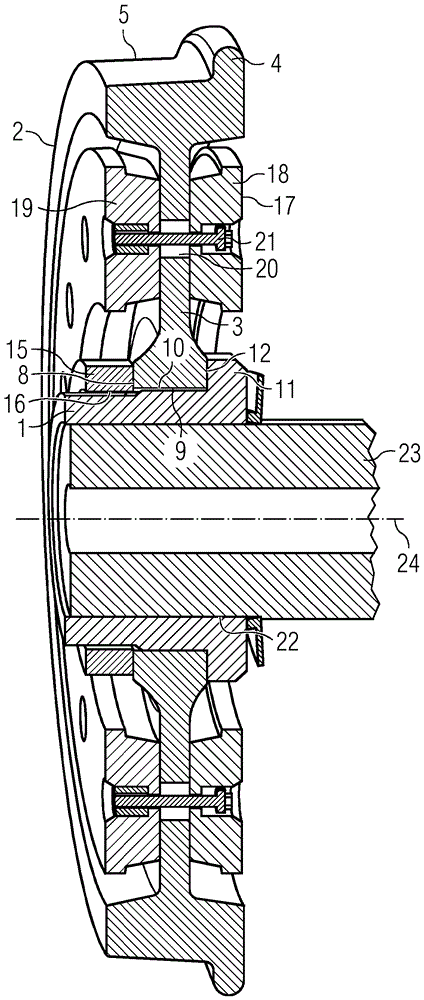
图1示出了根据本实用新型的轮的示例性的实施方案的截面图的第一视图,轮具有第一轮毂、第一轮体和布置在其上的轮制动盘;Figure 1 shows a first view of a cross-sectional view of an exemplary embodiment of a wheel having a first hub, a first wheel body and a wheel brake disc arranged thereon;
图2示出了根据图1的根据本实用新型的轮的示例性的实施方案的第二视图;和Fig. 2 shows a second view of the exemplary embodiment of the wheel according to the present invention according to Fig. 1; and
图3示出了具有根据本实用新型的轮的内支承的底盘的俯视图。Figure 3 shows a top view of a chassis with an inner support of a wheel according to the invention.
具体实施方式Detailed ways
截面图的在图1中示出的第一视图公开了针对轨道车辆的底盘的、根据本实用新型的轮的变型方案。轮包括构造为具有凸缘11的短管的第一轮毂1和第一轮体2,第一轮体具有轮辐3和轮圈,轮圈包括轮缘4和滚动面5。轮辐3和轮缘4构造为一个结构单元。没有设置与轮辐3分离地实施的并且例如形状配合或传力地与轮辐连接的轮胎。在第一轮毂1的外罩面9上布置有轮辐3,并且轮辐通过内罩面10接触第一轮毂1。此外,轮辐3接触第一轮毂1的凸缘11。在凸缘11的区域内,第一轮毂1和轮辐3具有接触区域。在该接触区域中设置有啮合部12,其在图2中详细示出。The first view of the sectional view shown in FIG. 1 discloses a variant of the wheel according to the invention for a chassis of a rail vehicle. The wheel comprises a
在第一轮毂1的外罩面9上构造有螺纹16,安全的张紧元件15旋拧到螺纹上。张紧元件15在第三端面8的区域中接触轮辐3,使第一轮体2和第一轮毂1相互压紧,并且使第一轮体2固定在第一轮毂1上,以防沿轮组纵轴线24的方向的滑动。张紧元件15构造为具有未示出的、由现有技术已知的楔形保险垫圈的中心螺母。楔形保险垫圈布置在张紧元件15与轮辐3之间,并且基于楔形作用产生在张紧元件15与轮辐3之间的夹紧力。在此涉及螺栓保险装置的有利的解决方案。然而根据本实用新型也可以想到的是,张紧元件15具有由现有技术已知的多重螺栓。在具有多重螺栓的张紧元件15的实施方案中,多个压力螺栓布置在张紧元件15的圆环形的基本面上,基本面的轴线平行于轮组纵轴线24地延伸。在张紧元件15与轮辐3之间布置有压力垫圈,压力螺栓相对于压力垫圈压紧,并且为了将张紧元件15固定在第一轮毂1上而施加压力。根据本实用新型,其他的同样由现有技术已知的螺栓保险装置也是可想到的。例如,粘合剂可以用作材料融合的螺栓保险装置,锁紧螺母、夹紧螺母或夹紧螺栓可以用作传力的螺栓保险装置,或开口销、金属线、板材或锁环可以用作形状配合的螺栓保险装置。A
在轮辐3上布置有由现有技术已知的轮制动盘17,其具有第一摩擦环18和第二摩擦环19。在第一钻孔20中布置有第一螺栓21,第一钻孔延伸穿过轮辐3、第一摩擦环18和第二摩擦环19。设置了另外的钻孔,另外的钻孔同样延伸穿过轮辐3、第一摩擦环18和第二摩擦环19,并且在另外的钻孔中布置有另外的螺栓。第一钻孔20和另外的钻孔设置在具有限定的直径的孔圆上。轮制动盘17基于第一螺栓21和另外的螺栓与轮辐3压紧,并且由此固定在第一轮体2上。根据本实用新型也可想到的是,没有制动盘布置在根据本实用新型的轮上,或者蹄式制动器作用到轮的滚动面5上等。Arranged on the
第一轮毂1布置在底盘的实施为空心轴的轮组轴23上,并且利用内部罩面接触轮组轴的外部罩面。根据本实用新型也可想到的是,轮组轴23构造为实心轴。在第一轮毂1与轮组轴23之间设置有柱形的压配合22,基于压配合,第一轮毂1被固定,以防相对于轮组轴23的扭转和滑动。在此涉及有利的解决方案。然而根据本实用新型也可想到的是,在第一轮毂1与轮组轴23之间设置锥形的压接合。The
第一轮毂1、第一轮体2、张紧元件15、轮制动盘17和轮组轴23相对于轮组纵轴线24同中心地布置。The
图2示出用于轨道车辆的底盘的、根据本实用新型的轮的变型方案的在图1中公开的截面图的第二视图。在图2中部分使用和在图1中相同的附图标记。在第一轮毂1上布置有第一轮体2,其中第一轮毂1的外罩面9接触第一轮体2的内罩面10。第一轮体2借助设置在第一轮毂1的螺纹16上的并且通过第三端面8接触第一轮体的张紧元件15压抵第一轮毂1的凸缘11,并且由此沿轮组纵轴线24的方向固定在第一轮毂1上。在第一轮体2的轮辐3上布置有轮制动盘17,其包括第一摩擦环18和第二摩擦环19。第一轮毂1通过柱形的压配合22布置和固定在轮组轴23上。FIG. 2 shows a second view of the sectional view disclosed in FIG. 1 of a variant of the wheel according to the invention for a chassis of a rail vehicle. In FIG. 2 the same reference numerals are used in part as in FIG. 1 . A
在第一轮毂1的第一端面6和轮辐3的第二端面7的区域中,第一轮毂1和第一轮体2具有接触区域,在接触区域中设置啮合部12。在第一轮毂1的第一端面6上布置有第一齿缘13,并且在轮辐3的第二端面7上布置有第二齿缘14。第一齿缘13与第二齿缘14嵌接,或第一齿援13和第二齿缘14彼此接触。第一轮体2由此被固定,以防相对于第一轮毂1的无意的扭转,并且在第一轮毂1与第一轮体2之间传输力和转矩。In the region of the first end face 6 of the
啮合部12实施为扁平啮合部(其由现有技术作为端齿连接或作为平切口啮合部已知)或与端侧的楔形轴类似地实施。由此实现对存在的结构空间预算的特别好的使用,以及实现第一齿缘13和第二齿缘14的各个V形地实施的齿之间的特别小的中间空间。由此,啮合部12被很好地保护,以防受到环境影响并且因此以防受到腐蚀。近似无间隙地在第一轮毂1和第一轮体2之间传输力和转矩。啮合部12布置在端侧,其中这涉及有利的解决方案。The
然而根据本实用新型也可想到的是,啮合部12布置在周边侧,其中第一齿缘13设置在第一轮毂1的外罩面9上,第二齿缘14设置在轮辐3的内罩面10上。According to the invention, however, it is also conceivable that the
啮合部12基于由现有技术已知的有限元方法(FEM)并且借助相应的计算确定规格。然而根据本实用新型,其他的同样由现有技术已知的设计方法也是可想到的。啮合部12在由现有技术已知的5轴加工中心上借助铣削加工制成。然而根据本实用新型,其他的同样由现有技术已知的制造器件和制造方法也是可想到的。The
为了将第一轮体2安装在第一轮毂1上,第一轮体2安放到第一轮毂1上,从而第一轮毂1的外罩面9接触第一轮体2的内罩面10。由此,第一轮体2被固定,以防从第一轮毂1掉落。随后,第一轮体2的第二齿缘14与第一轮毂1的第一齿缘13嵌接,以便固定第一轮体2,以防相对于第一轮毂1的无意的扭转。因此,张紧元件15旋拧到第一轮毂1的螺纹16上,并且压抵轮辐3,即张紧元件15被拧紧,由此,第一轮体2和第一轮毂1相互压紧。为了拆卸,张紧元件15被松开,并且从第一轮毂1拉出。随后,第一轮体2从第一轮毂1拉出。安装和拆卸可以简单地并且以很小的时间耗费执行。例如可能的是,为了更换轮制动盘17,将第一轮体2和轮制动盘17一起从第一轮毂1拉出,并且通过具有预安装的轮制动盘17的另一第一轮体2替代。然而根据本实用新型也可能的是,轮制动盘17从第一轮体2拆卸或者安装到其上。To mount the
图3中示出示例性的内支承的底盘的俯视图,底盘用于具有示例性的根据本实用新型的轮的轨道车辆。底盘具有带有轮组轴23、第一轮体2和第二轮体26的第一轮组25,以及在结构上与第一轮组25相同地构造的未示出的第二轮组,第二轮组与底盘框架29连接。底盘具有内支承件,即第一轮组25在第一轮体2与第二轮体26之间的区域中通过第一轮组轴承27和第二轮组轴承28耦联地或可转动地支承在底盘框架29上。根据相同的原理,第二轮组通过未示出的第三轮组轴承和第四轮组轴承连接式地或可转动地支承在底盘框架29上。A top view of an exemplary internally supported chassis for a rail vehicle with an exemplary wheel according to the invention is shown in FIG. 3 . The chassis has a first wheel set 25 with a
此外,在底盘框架29与第一轮组25之间以及在底盘框架29与第二轮组之间布置有第一初级弹簧30、第二初级弹簧31以及未示出的第三初级弹簧和第四初级弹簧。第一驱动马达-变速器单元32支承在底盘框架29中,并且为了传输驱动力矩和制动力矩与第一轮组25耦联。未示出的第二驱动马达-变速器单元同样支承在底盘框架29中,并且与第二轮组耦联。Furthermore, between the
轮组轴23与第一轮毂1通过柱形的压配合22连接。在第一轮毂1上布置有第一轮体2,第一轮体具有轮辐3、轮缘4和滚动面5。第一轮毂1的外罩面9接触第一轮体2的内罩面10。第一轮体2通过尤其是也在图2中示出的啮合部12固定,以防相对于第一轮毂1的扭转。啮合部12具有布置在第一轮毂1的凸缘11的第一端面6上的第一齿缘13和布置在轮辐3的第二端面7上的第二齿缘14。第一齿缘13与第二齿缘14嵌接。通过旋拧到第一轮毂1的螺纹16上的并且经由轮辐3的第三端面8接触第一轮体2的张紧元件15(其也在图1和2中示出),第一轮体2和第一轮毂1相互压紧,并且在第一轮毂1上,第一轮体2被固定以防沿轮组纵轴线24的方向的滑动。The
为了拆卸第一轮体2,张紧元件15被松开,并且从第一轮毂1拉出。随后拉出第一轮体2。拆卸和安装第一轮体2可以简单地和快速地从底盘的外侧执行。第一轮组25从底盘拆卸或者第一轮组25与底盘框架29分离为此不是必需的。In order to disassemble the
第一轮组25的第二轮体26在结构和连接技术原理方面与第一轮体2相同地实施。The
根据本实用新型,例如也可想到的是,底盘具有外支承件(即轮组轴23在轮之间的区域外部通过轴承与底盘框架29连接),构造为无驱动器的运行底盘或惰轮底盘,例如对于低底板车辆公知的那样。此外也可想到的是,底盘仅具有一个或具有多于两个的轮组。According to the invention, it is also conceivable, for example, for the undercarriage to have an outer bearing (ie the
附图标记列表List of reference signs
1第一轮毂1 first hub
2第一轮体2 first wheel body
3轮辐3 spokes
4轮缘4 rims
5滚动面5 rolling surfaces
6第一端面6 first end face
7第二端面7 Second end face
8第三端面8 Third end face
9外罩面9 outer cover
10内罩面10 inner cover
11凸缘11 flange
12啮合部12 engaging parts
13第一齿缘13 First Rim
14第二齿缘14 Second Rim
15张紧元件15 tensioning elements
16螺纹16 threads
17轮制动盘17 wheel brake disc
18第一摩擦环18 First friction ring
19第二摩擦环19 Second friction ring
20第一钻孔20 first drilling
21第一螺栓21 first bolt
22压配合22 Press fit
23轮组轴23 wheel set axle
24轮组纵轴线24 wheel longitudinal axis
25第一轮组25 first round group
26第二轮体26 second wheel body
27第一轮组轴承27 first wheel set bearing
28第二轮组轴承28 second wheel set bearing
29底盘框架29 chassis frame
30第一初级弹簧30 First Primary Spring
31第二初级弹簧31 Second Primary Spring
32第一驱动马达-变速器单元。32 First drive motor-transmission unit.
Claims (10)
Applications Claiming Priority (3)
| Application Number | Priority Date | Filing Date | Title |
|---|---|---|---|
| ATA50344/2017A AT519892B1 (en) | 2017-04-27 | 2017-04-27 | Wheel for vehicles |
| ATA50344/2017 | 2017-04-27 | ||
| PCT/EP2018/060635 WO2018197581A1 (en) | 2017-04-27 | 2018-04-25 | Wheel for rail vehicles |
Publications (1)
| Publication Number | Publication Date |
|---|---|
| CN211892714U true CN211892714U (en) | 2020-11-10 |
Family
ID=62148317
Family Applications (1)
| Application Number | Title | Priority Date | Filing Date |
|---|---|---|---|
| CN201890000776.5U Active CN211892714U (en) | 2017-04-27 | 2018-04-25 | Wheel for a rail vehicle, inner support chassis, outer support chassis and rail vehicle |
Country Status (4)
| Country | Link |
|---|---|
| EP (1) | EP3573844B1 (en) |
| CN (1) | CN211892714U (en) |
| AT (1) | AT519892B1 (en) |
| WO (1) | WO2018197581A1 (en) |
Families Citing this family (5)
| Publication number | Priority date | Publication date | Assignee | Title |
|---|---|---|---|---|
| AT521883B1 (en) | 2018-12-12 | 2020-12-15 | Siemens Mobility Austria Gmbh | Wheel set for a rail vehicle |
| AU2021203541B2 (en) * | 2020-06-19 | 2023-03-16 | Westinghouse Air Brake Technologies Corporation | Brake assembly |
| AT524669B1 (en) | 2021-04-23 | 2022-08-15 | Siemens Mobility Austria Gmbh | Rail vehicle undercarriage wheel, rail vehicle undercarriage and method of manufacturing a rail vehicle undercarriage wheel |
| EP4422884A4 (en) * | 2021-10-27 | 2025-10-29 | Iw Tech Llc | Universal spinner wheel |
| EP4316866A1 (en) * | 2022-08-03 | 2024-02-07 | Ernst Dipl.-Ing. Gschweitl | Light weight wheel set for a rail vehicle |
Family Cites Families (5)
| Publication number | Priority date | Publication date | Assignee | Title |
|---|---|---|---|---|
| US174051A (en) * | 1876-02-22 | Improvement in elastic car-wheels | ||
| US1039668A (en) * | 1912-05-28 | 1912-09-24 | John F Franklin | Locomotive drive-wheel. |
| DE1605077A1 (en) * | 1966-06-25 | 1971-01-14 | Krauss Maffei Ag | Wheel set with monoblock wheels for rail vehicles, especially rail locomotives |
| CN201257872Y (en) * | 2008-08-23 | 2009-06-17 | 唐山轨道交通装备有限责任公司 | Multiple layer rubber elastic wheelset |
| CN201693980U (en) * | 2010-02-08 | 2011-01-05 | 北京中冶设备研究设计总院有限公司 | A wheel for electric flat car with insulation function |
-
2017
- 2017-04-27 AT ATA50344/2017A patent/AT519892B1/en active
-
2018
- 2018-04-25 CN CN201890000776.5U patent/CN211892714U/en active Active
- 2018-04-25 EP EP18723738.3A patent/EP3573844B1/en active Active
- 2018-04-25 WO PCT/EP2018/060635 patent/WO2018197581A1/en not_active Ceased
Also Published As
| Publication number | Publication date |
|---|---|
| EP3573844B1 (en) | 2021-04-21 |
| AT519892A1 (en) | 2018-11-15 |
| AT519892B1 (en) | 2019-02-15 |
| EP3573844A1 (en) | 2019-12-04 |
| WO2018197581A1 (en) | 2018-11-01 |
Similar Documents
| Publication | Publication Date | Title |
|---|---|---|
| CN211892714U (en) | Wheel for a rail vehicle, inner support chassis, outer support chassis and rail vehicle | |
| US20040140164A1 (en) | Brake rotor attachment assembly that promotes in plane uniform torque transfer distribution | |
| US8651247B2 (en) | Direct drive braking system including an integrated package bearing | |
| US6196639B1 (en) | Vehicle wheel hub mounting system | |
| JP2011514862A5 (en) | ||
| US9303705B2 (en) | Brake disc and mounting arrangement for a brake disc | |
| CA2617522C (en) | Brake support plate | |
| US20160025165A1 (en) | Brake Disc Mounting Arrangement | |
| US20130175849A1 (en) | Wheel Assembly for Motor Vehicles | |
| CN101208209B (en) | Wheel carrier for vehicle with disk brake | |
| KR20110022449A (en) | Axle assembly | |
| JP2005517580A (en) | Wheel hub assembly | |
| US6889802B2 (en) | Wheel hub | |
| CN106004232A (en) | Omnidirectional wheel, omnidirectional wheel set and carrier cart using omnidirectional wheel or omnidirectional wheel set | |
| JP7143976B2 (en) | Reusable rims for non-pneumatic tires | |
| JP2001080308A (en) | Wheel bearing device | |
| US7070337B2 (en) | Wheel bearing for a driven rigid axle | |
| CN103889734B (en) | Axle system | |
| CN102821975B (en) | Wheel bearings for vehicles | |
| CN110962502B (en) | Elastic wheel for railway vehicle, use method of elastic wheel and independent wheel set | |
| CN104395632B (en) | Braking device | |
| CN201646877U (en) | Automobile brake angle assembly | |
| CN210830246U (en) | Disc type braking device and split type brake disc thereof | |
| KR102580864B1 (en) | Wheel bearing assembly | |
| CN106870605A (en) | For the connecting element being connected with brake disc structure and wheel bearing unit |
Legal Events
| Date | Code | Title | Description |
|---|---|---|---|
| GR01 | Patent grant | ||
| GR01 | Patent grant |