CN211898043U - A road bridge safety fence - Google Patents
A road bridge safety fence Download PDFInfo
- Publication number
- CN211898043U CN211898043U CN202020531421.8U CN202020531421U CN211898043U CN 211898043 U CN211898043 U CN 211898043U CN 202020531421 U CN202020531421 U CN 202020531421U CN 211898043 U CN211898043 U CN 211898043U
- Authority
- CN
- China
- Prior art keywords
- fixedly connected
- main body
- road
- sides
- spring
- Prior art date
- Legal status (The legal status is an assumption and is not a legal conclusion. Google has not performed a legal analysis and makes no representation as to the accuracy of the status listed.)
- Expired - Fee Related
Links
Images


Landscapes
- Road Signs Or Road Markings (AREA)
- Refuge Islands, Traffic Blockers, Or Guard Fence (AREA)
Abstract
本实用新型公开了一种道路桥梁安全防护栏,包括装置主体、凹槽壁和连接道,装置主体的顶部固定连接有凹槽壁,装置主体的内部固定连接有连接道,连接道的内部固定连接有主体弹簧,主体弹簧的底部固定连接有活动块,活动块的底部中间部位固定连接有支撑弹簧,支撑弹簧的两侧固定连接有装置柱,装置柱的内部固定连接有加固板,加固板的两侧底部固定连接有装置底座,装置底座的表面固定连接有装置灯,装置灯提高了装置主体的安全性,橡胶垫对装置起到了保护作用,凹槽提高了装置主体的实用性,减震机构大大的提高了装置主体的安全性,霓虹机构方便了传递信息给路人知晓护栏的位置,适用于安全防护栏的使用,在未来具有广泛的发展前景。

The utility model discloses a road and bridge safety guardrail, which comprises a device main body, a groove wall and a connecting road. The top of the device main body is fixedly connected with the groove wall, the interior of the device main body is fixedly connected with a connecting road, and the interior of the connecting road is fixed The main body spring is connected, the bottom of the main body spring is fixedly connected with a movable block, the middle part of the bottom of the movable block is fixedly connected with a support spring, the two sides of the support spring are fixedly connected with a device column, and the inside of the device column is fixedly connected with a reinforcing plate, a reinforcing plate The device base is fixedly connected to the bottom of the two sides of the device base, and the device lamp is fixedly connected to the surface of the device base. The device lamp improves the safety of the device main body, the rubber pad protects the device, and the groove improves the practicability of the device main body. The vibration mechanism greatly improves the safety of the main body of the device, and the neon mechanism facilitates the transmission of information to passersby to know the position of the guardrail, which is suitable for the use of safety guardrails and has broad development prospects in the future.
Description
技术领域technical field
本实用涉及道路安全防护技术领域,具体为一种道路桥梁安全防护栏。The utility relates to the technical field of road safety protection, in particular to a road bridge safety protection fence.
背景技术Background technique
道路桥梁的安全防护栏大多由钢材或水泥制造,结构设计简单,仅仅为连接有横杆的立柱形状。传统的防护栏为刚性结构,汽车冲撞到防护栏之后由于受到刚性冲击,无缓冲力作用,汽车会受到十分强烈的反作用力,容易给车上人员造成巨大威胁。Most of the safety fences of road bridges are made of steel or cement, and the structure design is simple, only in the shape of columns connected with cross bars. The traditional guardrail is a rigid structure. After the car collides with the guardrail, due to the rigid impact and no buffering force, the car will be subjected to a very strong reaction force, which is easy to cause a huge threat to the people in the car.
现有的安全防护栏一般都为铁质栏杆,在道路交通中只能起到简单的隔离作用,在发生交通事故时,车辆容易冲出防护栏而发生交通事故,且防撞性能低,无法降低撞击对安全防护栏的伤害,现有的安全防护栏的观赏性与传输信息较差,因夜晚的光线较差使车辆里的人不易观察到四周环境的信息,容易使路人出现车祸。The existing safety guardrails are generally iron guardrails, which can only play a simple isolation role in road traffic. In the event of a traffic accident, the vehicle easily rushes out of the guardrail to cause a traffic accident, and the anti-collision performance is low and cannot be used. To reduce the damage to the safety fence caused by the impact, the existing safety fence has poor viewing and transmission information. Due to the poor light at night, it is difficult for people in the vehicle to observe the information of the surrounding environment, and it is easy for passers-by to have a car accident.
所以,如何设计一种道路桥梁安全防护栏,成为我们当前需要解决的问题。Therefore, how to design a road and bridge safety fence has become a problem that we need to solve at present.
发明内容SUMMARY OF THE INVENTION
本实用新型的目的在于提供一种道路桥梁安全防护栏,以解决上述背景技术中提出的减震较差,不易传递信息的问题。The purpose of the present utility model is to provide a road bridge safety fence, so as to solve the problems of poor shock absorption and difficulty in transmitting information proposed in the above-mentioned background art.
为实现上述目的,本实用新型提供如下技术方案:一种道路桥梁安全防护栏,包括装置主体、凹槽壁和连接道,所述装置主体的顶部固定连接有凹槽壁,所述装置主体的内部固定连接有连接道,所述连接道的内部固定连接有主体弹簧,所述主体弹簧的底部固定连接有活动块,所述活动块的底部中间部位固定连接有支撑弹簧,所述支撑弹簧的两侧固定连接有装置柱,所述装置柱的内部固定连接有加固板,所述加固板的两侧底部固定连接有装置底座,所述凹槽壁的外围固定连接有散光孔,所述散光孔的底部内部两侧固定连接有连接块,所述连接块的顶部固定连接有霓虹灯,所述霓虹灯的外围固定连接有保护壳,所述保护壳的底部两侧固定连接有电路线,所述装置底座的两侧嵌入连接有螺旋钉。In order to achieve the above purpose, the present utility model provides the following technical solutions: a road and bridge safety fence, comprising a device main body, a groove wall and a connecting road, the top of the device main body is fixedly connected with the groove wall, and the A connecting channel is fixedly connected inside, a main body spring is fixedly connected inside the connecting channel, a movable block is fixedly connected to the bottom of the main body spring, and a support spring is fixedly connected to the middle part of the bottom of the movable block. Device columns are fixedly connected on both sides, reinforcement plates are fixedly connected to the inside of the device columns, device bases are fixedly connected to the bottoms of the two sides of the reinforcement plates, and astigmatic holes are fixedly connected to the periphery of the groove wall, and the astigmatism A connecting block is fixedly connected on both sides of the bottom of the hole, a neon light is fixedly connected to the top of the connecting block, a protective shell is fixedly connected to the periphery of the neon light, and circuit wires are fixedly connected to both sides of the bottom of the protective shell. The two sides of the base of the device are embedded and connected with screw nails.
优选的,所述电路线的上方固定连接有装置灯。Preferably, a device lamp is fixedly connected above the circuit wire.
优选的,所述装置主体的顶部固定连接有橡胶垫。Preferably, a rubber pad is fixedly connected to the top of the device body.
优选的,所述凹槽壁的内部活动连接有凹槽。Preferably, a groove is movably connected inside the groove wall.
优选的,所述装置主体内部的连接道,连接道内部的主体弹簧,主体弹簧底部的活动块,活动块底部中间部位的支撑弹簧,支撑弹簧两侧的装置柱,装置柱内部的加固板,加固板两侧底部的装置底座共同组成减震机构。Preferably, the connecting channel in the main body of the device, the main body spring in the connecting channel, the movable block at the bottom of the main spring, the support spring in the middle part of the bottom of the movable block, the device column on both sides of the support spring, the reinforcement plate inside the device column, The device bases at the bottoms of the two sides of the reinforcing plate together form a shock absorption mechanism.
优选的,所述装置主体顶部的凹槽壁,凹槽壁外围的散光孔,散光孔底部内部两侧的连接块,连接块顶部的霓虹灯,霓虹灯外围的保护壳,保护壳底部两侧的电路线共同组成霓虹机构。Preferably, the groove wall on the top of the main body of the device, the astigmatism hole on the periphery of the groove wall, the connecting blocks on both sides of the bottom of the astigmatic hole, the neon light on the top of the connecting block, the protective shell on the periphery of the neon light, and the circuit on both sides of the bottom of the protective shell The lines together form a neon body.
与现有技术相比,本实用新型的有益效果是:Compared with the prior art, the beneficial effects of the present utility model are:
1.该种道路桥梁安全防护栏,通过设置减震机构,在装置主体内安装主体弹簧,当车辆在道路桥梁上行驶,不小心车辆撞击到防护栏时,主体弹簧进行减震和同时还会进行反作用力,使车辆不会使出道路,在主体弹簧底部的设置支撑弹簧,可使装置主体的减震性更加良好,减震机构大大的提高了装置主体的安全性,扩大了装置主体的适用范围。1. For this kind of road and bridge safety guardrail, by setting a shock absorption mechanism, the main body spring is installed in the main body of the device. When the vehicle is driving on the road bridge and the vehicle accidentally hits the guardrail, the main body spring will dampen the shock and will also The reaction force is carried out so that the vehicle will not go out of the road. The support spring is arranged at the bottom of the main body spring, which can make the shock absorption of the main body of the device better. Scope of application.
2.该种道路桥梁安全防护栏,通过设置霓虹机构,在连接块顶部设置霓虹灯,保护壳底部两侧的电路线可连接路灯电路,可在夜晚准时开启,透过散光孔进行发亮,当车辆行驶在道路桥梁上,可清晰的看见护栏的位置,同时霓虹机构也可进行美化环境,与装置灯相互配合工作,霓虹机构方便了他人知晓护栏的位置,也能美化环境。2. This kind of road and bridge safety guardrail, by setting up a neon mechanism, set neon lights on the top of the connection block, and the circuit lines on both sides of the bottom of the protective shell can be connected to the street light circuit, which can be turned on on time at night, and illuminated through the astigmatism hole, When the vehicle is driving on the road and bridge, the position of the guardrail can be clearly seen. At the same time, the neon mechanism can also beautify the environment and cooperate with the installed lights. The neon mechanism facilitates others to know the position of the guardrail and can also beautify the environment.
附图说明Description of drawings
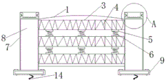
图1为本实用新型的整体结构示意图;Fig. 1 is the overall structure schematic diagram of the present utility model;
图2为本实用新型的整体顶部结构示意图;Fig. 2 is the overall top structure schematic diagram of the present utility model;
图3为本实用新型的整体表面示意图;Fig. 3 is the overall surface schematic diagram of the utility model;
图4为本实用新型的A处放大结构示意图。FIG. 4 is a schematic view of the enlarged structure of the A part of the present invention.
图中:1、装置主体,2、凹槽壁,3、连接道,4、主体弹簧,5、活动块,6、支撑弹簧,7、装置柱,8、加固板,9、装置底座,10、散光孔,11、连接块,12、霓虹灯,13、保护壳,14、电路线,15、螺旋钉,16、装置灯,17、橡胶垫,18、凹槽。In the figure: 1. Device main body, 2. Groove wall, 3. Connecting channel, 4. Main body spring, 5. Active block, 6. Support spring, 7. Device column, 8. Reinforcing plate, 9. Device base, 10 , Astigmatism hole, 11, connection block, 12, neon light, 13, protective shell, 14, circuit wire, 15, screw nail, 16, device light, 17, rubber pad, 18, groove.
具体实施方式Detailed ways
下面将结合本实用新型实施例中的附图,对本实用新型实施例中的技术方案进行清楚、完整地描述,显然,所描述的实施例仅仅是本实用新型一部分实施例,而不是全部的实施例,基于本实用新型中的实施例,本领域普通技术人员在没有做出创造性劳动前提下所获得的所有其他实施例,都属于本实用新型保护的范围。The technical solutions in the embodiments of the present utility model will be clearly and completely described below with reference to the accompanying drawings in the embodiments of the present utility model. Obviously, the described embodiments are only a part of the embodiments of the present utility model, rather than all the implementations. For example, based on the embodiments of the present invention, all other embodiments obtained by persons of ordinary skill in the art without creative work shall fall within the protection scope of the present invention.
请参阅图1-4,本实用新型提供技术方案:一种道路桥梁安全防护栏,包括装置主体1、凹槽壁2和连接道3,装置主体1的顶部固定连接有凹槽壁2,装置主体1的内部固定连接有连接道3,连接道3的内部固定连接有主体弹簧4,主体弹簧4的底部固定连接有活动块5,活动块5的底部中间部位固定连接有支撑弹簧6,支撑弹簧6的两侧固定连接有装置柱7,装置柱7的内部固定连接有加固板8,加固板8的两侧底部固定连接有装置底座9,凹槽壁2的外围固定连接有散光孔10,散光孔10的底部内部两侧固定连接有连接块11,连接块11的顶部固定连接有霓虹灯12,霓虹灯12的外围固定连接有保护壳13,保护壳13的底部两侧固定连接有电路线14,装置底座9的两侧嵌入连接有螺旋钉15。Please refer to FIGS. 1-4, the present utility model provides technical solutions: a road and bridge safety fence, comprising a device main body 1, a
优选的,电路线14的上方固定连接有装置灯16,现有的安全防护栏的功能性不佳,并不能很好的给路人传递信息,容易使路人在夜晚不易观察到护栏的位置导致车祸的发生,通过设置装置灯16,在电路线14的上方设置装置灯16,可在夜晚通电开启,装置灯16发出较强的光线,进行有效的给路人传输信息,使其知晓护栏的位置,装置灯16有效的避免了车祸意外的发生,提高了装置主体的安全性。Preferably, a
优选的,装置主体1的顶部固定连接有橡胶垫17,现有的安全防护栏大多并未在装置主体1的顶部设置橡胶垫17,因大雨的长年侵蚀,容易使装置主体1的寿命减短,通过设置橡胶垫17,橡胶垫17也可适当保护装置主体1免受雨水的侵蚀,同时也可进行更换橡胶垫17进行更好的养护护栏,橡胶垫17对装置起到了保护作用,延长了装置的使用寿命。Preferably, a
优选的,凹槽壁2的内部活动连接有凹槽18,现有的安全防护栏的因大多都是铁制造而成,容易因大雨的侵蚀而生锈,行人入过难免会问到铁锈味,使行人感到不适,通过设置凹槽18,在凹槽壁2的内部设置凹槽18,可在凹槽18的内部种植花草使花草的芳香掩盖铁锈的味道,同时也可为净化空气的道路上贡献一份力,凹槽18提高了装置主体的实用性。Preferably, a
优选的,装置主体1内部的连接道3,连接道3内部的主体弹簧4,主体弹簧4底部的活动块5,活动块5底部中间部位的支撑弹簧6,支撑弹簧6两侧的装置柱7,装置柱7内部的加固板8,加固板8两侧底部的装置底座9共同组成减震机构,现有的安全防护栏一般都为铁质栏杆,在道路交通中只能起到简单的隔离作用,在发生交通事故时,车辆容易冲出防护栏而发生交通事故,且防撞性能低,无法降低撞击对安全防护栏的伤害,通过设置减震机构,在装置主体1内安装主体弹簧4,当车辆在道路桥梁上行驶,不小心车辆撞击到防护栏时,主体弹簧4进行减震的同时还会进行反作用力,使车辆不会使出道路,在主体弹簧4底部的设置支撑弹簧6,可使装置主体1的减震性更加良好,减震机构大大的提高了装置主体的安全性,扩大了装置主体的适用范围。Preferably, the connecting channel 3 inside the device main body 1, the main body spring 4 inside the connecting channel 3, the
优选的,装置主体1顶部的凹槽壁2,凹槽壁2外围的散光孔10,散光孔10底部内部两侧的连接块11,连接块11顶部的霓虹灯12,霓虹灯12外围的保护壳13,保护壳13底部两侧的电路线14共同组成霓虹机构,现有的安全防护栏的观赏性与传输信息较差,因夜晚的光线较差使车辆里的人不易观察到四周环境的信息,容易使路人出现车祸,通过设置霓虹机构,在连接块11顶部设置霓虹灯12,保护壳13底部两侧的电路线14可连接路灯电路,可在夜晚准时开启,透过散光孔10进行发亮,当车辆行驶在道路桥梁上,可清晰的看见护栏的位置,同时霓虹机构也可进行美化环境,与装置灯16相互配合工作,霓虹机构方便了传递信息给路人知晓护栏的位置,也能美化环境,提高了装置主体的实用性。Preferably, the
工作原理:首先,通过设置减震机构,在装置主体1内安装主体弹簧4,当车辆在道路桥梁上行驶,不小心车辆撞击到防护栏时,主体弹簧4进行减震的同时还会进行反作用力,使车辆不会使出道路,在主体弹簧4底部的设置支撑弹簧6,可使装置主体1的减震性更加良好,减震机构大大的提高了装置主体的安全性,扩大了装置主体的适用范围;Working principle: First of all, by setting the shock absorption mechanism, the main body spring 4 is installed in the main body 1 of the device. When the vehicle is driving on the road bridge and the vehicle accidentally hits the guardrail, the main body spring 4 will dampen the shock and also react. The
然后,通过设置霓虹机构,在连接块11顶部设置霓虹灯12,保护壳13底部两侧的电路线14可连接路灯电路,可在夜晚准时开启,透过散光孔10进行发亮,当车辆行驶在道路桥梁上,可清晰的看见护栏的位置,同时霓虹机构也可进行美化环境,与装置灯16相互配合工作,霓虹机构方便了传递信息给路人知晓护栏的位置,也能美化环境,提高了装置主体的实用性;Then, by setting a neon mechanism, a
接着,通过设置凹槽18,在凹槽壁2的内部设置凹槽18,可在凹槽18的内部种植花草使花草的芳香掩盖铁锈的味道,同时也可为净化空气的道路上贡献一份力,凹槽18提高了装置主体的实用性;Next, by setting the
紧接着,通过设置橡胶垫17,橡胶垫17也可适当保护装置主体1免受雨水的侵蚀,同时也可进行更换橡胶垫17进行更好的养护护栏,橡胶垫17对装置起到了保护作用,延长了装置的使用寿命;Next, by setting the
最后,通过设置装置灯16,在电路线14的上方设置装置灯16,可在夜晚通电开启,装置灯16发出较强的光线,进行有效的给路人传输信息,使其知晓护栏的位置,装置灯16有效的避免了车祸意外的发生,提高了装置主体的安全性,这就是该种道路桥梁安全防护栏的工作原理。Finally, by setting the
尽管已经示出和描述了本实用新型的实施例,对于本领域的普通技术人员而言,可以理解在不脱离本实用新型的原理和精神的情况下可以对这些实施例进行多种变化、修改、替换和变型,本实用新型的范围由所附权利要求及其等同物限定。Although the embodiments of the present invention have been shown and described, it will be understood by those skilled in the art that various changes and modifications can be made to these embodiments without departing from the principles and spirit of the present invention , alternatives and modifications, the scope of the present invention is defined by the appended claims and their equivalents.
Claims (7)
Priority Applications (1)
| Application Number | Priority Date | Filing Date | Title |
|---|---|---|---|
| CN202020531421.8U CN211898043U (en) | 2020-04-13 | 2020-04-13 | A road bridge safety fence |
Applications Claiming Priority (1)
| Application Number | Priority Date | Filing Date | Title |
|---|---|---|---|
| CN202020531421.8U CN211898043U (en) | 2020-04-13 | 2020-04-13 | A road bridge safety fence |
Publications (1)
| Publication Number | Publication Date |
|---|---|
| CN211898043U true CN211898043U (en) | 2020-11-10 |
Family
ID=73276074
Family Applications (1)
| Application Number | Title | Priority Date | Filing Date |
|---|---|---|---|
| CN202020531421.8U Expired - Fee Related CN211898043U (en) | 2020-04-13 | 2020-04-13 | A road bridge safety fence |
Country Status (1)
| Country | Link |
|---|---|
| CN (1) | CN211898043U (en) |
-
2020
- 2020-04-13 CN CN202020531421.8U patent/CN211898043U/en not_active Expired - Fee Related
Similar Documents
| Publication | Publication Date | Title |
|---|---|---|
| CN210737371U (en) | A guardrail based on road and bridge design | |
| CN208517816U (en) | A kind of road and bridge anticollision barrier | |
| CN205529888U (en) | Multi -functional municipal bridge railing | |
| CN207211013U (en) | Crash barrier with shock-absorbing capacity | |
| CN207362747U (en) | A kind of urban road isolation roadblock with collision prevention function | |
| CN211898043U (en) | A road bridge safety fence | |
| CN209991360U (en) | Municipal street lamp of external anticollision strip | |
| KR100899574B1 (en) | Shock absorber installed on the street lamp of the road | |
| CN211849154U (en) | Follow-on road traffic facilities flexible protector | |
| CN210684548U (en) | A highway bridge isolation fence | |
| CN203361056U (en) | Urban road central dividing strip isolation guardrail | |
| CN211849086U (en) | Novel construction roadblock | |
| CN114232533B (en) | Cable guardrail and side slope protective fence capable of automatically opening alarm mark | |
| CN210031622U (en) | Luminous anti-collision road guardrail | |
| CN213476729U (en) | Anticollision barrier is used in town road installation protection | |
| CN211665648U (en) | A kind of protective fence for municipal public works | |
| CN219735128U (en) | An anti-collision municipal street light | |
| CN203514218U (en) | Noise reduction barrier capable of preventing flying birds from impacting | |
| CN212248003U (en) | A kind of isolation fence for highway construction | |
| CN209066338U (en) | A kind of high corrosion resistant zinc steel highway barrier enhancing safety | |
| CN219298024U (en) | Safety island | |
| CN206928226U (en) | Town road impact resistance Anti-collision barrel | |
| CN209798614U (en) | A buffer device for highway guardrail | |
| CN219808261U (en) | Combined road and bridge guardrail | |
| CN220767856U (en) | Anti-collision structure for street lamp post |
Legal Events
| Date | Code | Title | Description |
|---|---|---|---|
| GR01 | Patent grant | ||
| GR01 | Patent grant | ||
| CF01 | Termination of patent right due to non-payment of annual fee |
Granted publication date: 20201110 |
|
| CF01 | Termination of patent right due to non-payment of annual fee |