CN211945314U - Many chucks of baked brick unload brick device - Google Patents
Many chucks of baked brick unload brick device Download PDFInfo
- Publication number
- CN211945314U CN211945314U CN201922333373.1U CN201922333373U CN211945314U CN 211945314 U CN211945314 U CN 211945314U CN 201922333373 U CN201922333373 U CN 201922333373U CN 211945314 U CN211945314 U CN 211945314U
- Authority
- CN
- China
- Prior art keywords
- unit
- hanger
- guide mechanism
- clamping
- brick
- Prior art date
- Legal status (The legal status is an assumption and is not a legal conclusion. Google has not performed a legal analysis and makes no representation as to the accuracy of the status listed.)
- Active
Links
- 239000011449 brick Substances 0.000 title claims abstract description 66
- 230000007246 mechanism Effects 0.000 claims abstract description 84
- 238000000034 method Methods 0.000 claims description 6
- 238000003825 pressing Methods 0.000 claims description 6
- 238000004519 manufacturing process Methods 0.000 abstract description 7
- 230000001360 synchronised effect Effects 0.000 abstract 1
- 230000009471 action Effects 0.000 description 3
- 238000007599 discharging Methods 0.000 description 3
- 230000008569 process Effects 0.000 description 3
- 230000008859 change Effects 0.000 description 2
- 230000007547 defect Effects 0.000 description 1
- 230000000694 effects Effects 0.000 description 1
- 230000005489 elastic deformation Effects 0.000 description 1
- 238000009434 installation Methods 0.000 description 1
- 230000004048 modification Effects 0.000 description 1
- 238000012986 modification Methods 0.000 description 1
- 230000001105 regulatory effect Effects 0.000 description 1
Images


Landscapes
- Furnace Housings, Linings, Walls, And Ceilings (AREA)
Abstract
The utility model relates to a multi-chuck brick unloading device for baked bricks, which comprises a hanger, a guide mechanism I, a plurality of unit gripper groups and a power device I, wherein the guide mechanism I, the plurality of unit gripper groups and the power device I are arranged under the hanger, the plurality of unit gripper groups are connected through a synchronous mechanism, and the power device I drives the unit gripper groups to horizontally move along the direction of the guide mechanism I; each unit gripper group further comprises a sub-hanger, a guide mechanism II arranged below the sub-hanger, a power device II, a plurality of unit small grippers, a corresponding floating mechanism and a rotating mechanism, the plurality of unit small grippers are arranged on the guide mechanism II and driven by the power device II to horizontally move along the direction of the guide mechanism II, and can independently rotate and float at the same time, and reliable clamping and stacking and unloading of different air channels, different stack shapes and deformed brick stacks are realized by adjusting the distance between the unit gripper groups and between the unit small grippers and the rotation or floating of the unit small grippers, so that the production efficiency is improved, and the universal adaptability of mechanical brick unloading is expanded.
Description
Technical Field
The utility model relates to a baked brick production facility technical field, concretely relates to many chucks of baked brick unload brick device.
Background
Along with the application of mechanized automation equipment, in the automatic production process of baked bricks, the stacking process of green bricks from a conveyor to a kiln car is a trend of robot stacking, particularly, the stacking process of large-section kiln bodies including rotary kilns is more advantageous, the stacking is characterized in that the whole stacking is unitized, longitudinal and transverse air channels can be randomly adjusted according to the requirements of the kiln bodies and the kiln cars, the stacked whole stacking can be rectangular or square, and in order to ensure the roasting quality and the stacking stability, the layers are stacked in a crossed manner, so that the mechanical clamping hands rotate when the bricks are unloaded, and the requirements of different air channels and stacking shapes in different directions are met; in addition, the dimension error of the brick body after being roasted by the kiln is large, the stacking shape is changed irregularly, the phenomena of missing clamping and falling of the brick are often caused by the conventional mechanical clamping, the production is seriously influenced, and the realization of mechanical brick unloading is restricted.
The brick unloading clamping jaw structure in the prior art needs to grab a plurality of piled bricks arranged in an array simultaneously, the clamping jaw is composed of a plurality of clamping pieces side by side, the relative positions of the clamping pieces are fixed according to the piling requirement of the piled bricks, the clamping jaw can realize integral rotation, the piled bricks which are piled are shaped into a square, the longitudinal air channel and the transverse air channel which correspond to the integral clamping jaw after the integral clamping jaw rotates 90 degrees are consistent, thereby realizing integral cross piling and unloading of the piled bricks, the clamping jaw structure determines that the piled bricks which are piled and unloaded need to be the square, and the longitudinal air channel and the transverse air channel which correspond to the square after the piled bricks are rotated 90 degrees are equal, so that piling and unloading can be realized, and the piling and unloading of different air channels which are rectangular and longitudinally and.
SUMMERY OF THE UTILITY MODEL
To prior art's defect, the utility model aims to provide a many chucks of baked brick unload brick device can press from both sides by automatically regulated and get buttress shape and wind channel size, and the wind channel brick pillar that adapts to different requirements and the sign indicating number of warping the brick pillar are unloaded, effectively improve production efficiency.
In order to achieve the above purpose, the utility model adopts the technical scheme that: a multi-chuck brick unloading device for baked bricks comprises a hanger, a guide mechanism I arranged below the hanger, a plurality of unit gripper groups arranged at the bottom of the hanger through the guide mechanism I and a power device I, wherein the unit gripper groups are connected through a synchronization mechanism and driven by the power device I to horizontally move along the direction of the guide mechanism I; each unit gripper group also comprises a sub-hanger, a guide mechanism II arranged below the sub-hanger, a power device II, a plurality of unit small grippers, a corresponding floating mechanism and a corresponding swing mechanism, wherein the swing mechanism comprises a swing part and a connecting flange, the floating mechanism comprises a floating guide post and a limiting mechanism, a plurality of unit small grippers are arranged on a guide mechanism II at the bottom of the sub-hanger frame through the floating guide post and the swing mechanism and are driven by a power device II to realize horizontal movement along the direction of the guide mechanism II, can independently rotate and float, the horizontal directions of the guide mechanism I and the guide mechanism II are mutually vertical, the reliable clamping and stacking and unloading of different air ducts, different stack shapes and deformed brick stacks are realized by adjusting the distance between the unit clamping hand group and the distance between the unit small clamping hand and the rotation or floating of the unit small clamping hand.
Furthermore, the small unit clamping hand comprises a small unit hanging bracket, an inner clamping piece group, an outer clamping piece group and a power cylinder, wherein the inner clamping piece group comprises an inner clamping plate seat and an elastic clamping piece group.
Furthermore, the elastic clamping piece assembly comprises an elastic clamping piece, an elastic pressing piece and an elastic mechanism, wherein the elastic mechanism is a telescopic elastic element and is arranged between the elastic pressing piece and the elastic clamping piece.
Further, limiting mechanism installs under the little gallows of unit, including spacing support and adjustable limiting plate, adjusts the height of adjustable limiting plate through adjusting nut.
Furthermore, the plurality of small unit grippers are connected with a rotary part through a floating guide column, the rotary part is connected with a connecting flange into a whole, and the connecting flange is arranged on a guide mechanism II at the bottom of the sub-hanger.
Furthermore, the floating guide pillar is arranged between the small unit clamping hand and the swing mechanism, and the floating guide pillar is a stud, a bolt or a guide shaft for connection and guiding.
Furthermore, the rotary part is a rotary driving pair, a rotary support or a rotary gear pair.
Furthermore, the power device I and the power device II are cylinders, oil cylinders or electric cylinders, adjusting shaft sleeves are installed on cylinder rods, the adjusting shaft sleeves are divided into a plurality of types according to length and number, and power strokes of cylinder bodies can be adjusted.
Has the advantages that: the utility model is mainly used in the procedure of discharging bricks from a kiln and discharging bricks, a clamping mode that a plurality of clamping heads respectively rotate and move is adopted to clamp and discharge bricks for sintered finished brick piles, clamping hands are unitized, the stroke of each power cylinder or oil cylinder is firstly adjusted through the air channel requirement of the brick pile, and the length of a shaft sleeve arranged on a cylinder rod is ensured to respectively meet the requirements of each air channel, reliable grabbing and stacking and discharging of the brick piles with deformed concave centers and large dimensional error change of brick bodies are realized through the action of a floating mechanism and an elastic clamping piece assembly during operation, the utility model is particularly suitable for stacking the brick piles with different longitudinal and transverse air channels or long brick piles, the integral clamping hands are unitized, the whole is broken into parts, the air channel brick piles with different requirements are adapted, meanwhile, the unit clamping has more clamping advantages for clamping the deformed brick piles after being discharged from the kiln, the range of clamping the deformed brick piles is reduced, the unit control is convenient, each, the clamping is reliable, the production efficiency is improved, the universality and the adaptability of mechanical brick unloading are expanded, the brick unloading process is not influenced by the stack shape and the air duct, a client can stack different stack shapes according to the requirements of a kiln body and productivity, and the method is particularly important in the field of mechanical and automatic brick unloading.
Drawings
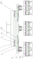
FIG. 1 is a schematic view of the multi-chuck brick unloading device for baked bricks according to the present invention;
FIG. 2 is a schematic side view of the multi-chuck brick unloading device for baked bricks of the present invention;
FIG. 3 is a schematic view of the elastic clip assembly of the present invention;
fig. 4 is a schematic view of the floating mechanism of the present invention;
reference numerals: the device comprises a hanging bracket 1, a guide mechanism I2, a unit gripper group 3, a sub-hanging bracket 301, a guide mechanism II 302, a power device II 303, an adjusting shaft sleeve 30301 II, a rotating mechanism 304, a 30401 connecting flange, a 30402 rotating part, a floating mechanism 305, a floating guide column 30501, a 30502 limiting mechanism 3050201 limiting support, an adjustable limiting plate 3050202, a unit gripper 306, a unit gripper 30601, a unit hanger 30602, an elastic clamping piece assembly 3060201, an elastic clamping piece 3060202, an elastic mechanism 3060203, a power device I4, an adjusting shaft sleeve I401 and a synchronizing mechanism 5.
Detailed Description
The present invention will be described in further detail with reference to the accompanying drawings and specific embodiments.
The embodiment of the present invention uses orientation terms such as front-back, left-right, etc., and only for the orientation presented in the drawings, it is intended to explain the embodiment with the drawings without limiting the absolute orientation of the technical solution of the present invention.
As shown in fig. 1-4, a multi-chuck baked brick unloading device comprises a hanger 1, a guide mechanism i 2 installed under the hanger, and a plurality of unit gripper groups 3 and a power device i 4 which are slidably installed on the guide mechanism i 2, wherein the plurality of unit gripper groups 3 are connected through a synchronizing mechanism 5, and are driven by the power device i 4 to realize the movement of the unit gripper groups 3 along the direction (left and right direction in fig. 1) of the guide mechanism i 2; each unit gripper set 3 comprises a sub-hanger 301, a guide mechanism II 302 arranged below the sub-hanger 301, a power device II 303, a plurality of rotary mechanisms 304, a unit small gripper 306 and a plurality of floating mechanisms 305, the horizontal directions of the guide mechanism I2 and the guide mechanism II 302 are perpendicular to each other, the rotary mechanisms 304 comprise rotary members 30402 and connecting flanges 30401, the floating mechanisms 305 comprise floating guide columns 30501 and limiting mechanisms 30502, the floating guide columns 30501 are connected between the unit small grippers 306 and the rotary mechanisms 304, the unit small grippers 306 are connected with the rotary members 30402 through the floating guide columns 30501, the connecting flanges 30401 in the rotary mechanisms 304 are connected with the guide mechanism II 302 arranged below the sub-hanger 301, the power device II 303 is used for realizing that the unit small gripper 306 is arranged along the direction of the guide mechanism II 302 (namely the front-back direction in figure 1 and the left-right direction in figure 2, also considered to be in the direction of the sub-hanger 301), the plurality of unit small grippers 306 can be independently rotated at the same time.
The power device I4 and the power device II 303 can be any movable power mechanism including an air cylinder, an oil cylinder, an electric cylinder and the like, the cylinder rods are respectively provided with an adjusting shaft sleeve, the adjusting shaft sleeves are divided into a plurality of types according to the length and the number, and the power stroke of the cylinder body can be adjusted; the distance between the unit clamping hand group 3 and the distance between the unit small clamping hand 306 and the unit small clamping hand 306 are adjusted by adjusting the stroke of the cylinder body and the lengths of the corresponding adjusting shaft sleeve I401 and adjusting shaft sleeve II 30301, so that the stacking and unloading of the brick pile with different vertical and horizontal air channels and long or square brick piles are realized.
The unit small clamping hand 306 comprises a unit small hanging bracket 30601, an inner clamping piece group, an outer clamping piece group and a power cylinder for driving the inner clamping piece group and the outer clamping piece group, the inner clamping piece group comprises an inner clamping piece seat and an elastic clamping piece assembly 30602, the elastic clamping piece assembly 30602 comprises an elastic clamping piece 3060201, an elastic pressing piece 3060202 and an elastic mechanism 3060203, the elastic mechanism 3060203 is installed between the elastic pressing piece 3060202 and an elastic clamping piece 3060201, the elastic mechanism 3060203 comprises a disc spring, a diaphragm spring and other telescopic elastic elements, the clamping distance of the brick thickness error is compensated through elastic deformation of the elastic elements, and therefore reliable clamping and stacking are achieved.
The rotating member 30402 includes, but is not limited to, a rotating body such as a rotating drive pair, a rotating support, a rotating gear pair, etc.; the limiting mechanism 30502 is arranged below each unit small hanging bracket 30601 and comprises a limiting bracket 3050201 and an adjustable limiting plate 3050202, the height of the adjustable limiting plate is adjusted through an adjusting nut, the floating guide pillar 30501 is arranged between the unit small clamping hand 306 and the rotating mechanism 304, and the floating guide pillar 30501 comprises but is not limited to a stud, a bolt, a guide shaft for connection and guiding and the like; the plurality of small unit grippers 306 can realize the floating of the unit stack by the positioning of the limiting mechanism 30502 and the up-and-down movement of the floating guide column 30501.
When the device works, according to the requirements of stack shape and air channel, the stroke of a power cylinder or oil cylinder between each unit clamping hand group and each unit small clamping hand and the length of a shaft sleeve arranged on a cylinder rod are adjusted to meet the requirements of a brick stack, according to the stack shape requirements, each power device is unfolded or folded in two directions of 0 degree and 90 degrees (namely two directions vertical to each other), the clamping hands move to the upper part of the brick stack, a hanger moves to the proper position of a gap between finished product brick stacks, an adjustable limiting plate of a limiting mechanism is downwards contacted with the upper part of a brick body, the unit small clamping hands are positioned through the limiting mechanism, the floating guide pillar moves up and down to realize the floating of the unit stack, each unit small clamping hand obliquely floats according to the brick stack, the inner clamping piece group and the outer clamping piece group perform clamping actions, and clamping and stacking are carried out under the elastic action of an elastic clamping piece assembly, so that the mechanical stable and reliable clamping, And (6) stacking and unloading.
The utility model discloses an installation axle sleeve's length on adjustment each power cylinder or hydro-cylinder stroke and the jar pole makes and satisfies each wind channel requirement respectively, and the effect through relocation mechanism and elasticity clamping piece subassembly realizes reliable grabbing sign indicating number and unloads appearing warping the concave center, the big brick pillar of brick body size error change, has improved production efficiency, has expanded the commonality that the brick was unloaded to machinery, and adaptability especially shows the importance in the brick field is unloaded in mechanized automation.
The above description is only a preferred embodiment of the present invention, and the present invention is not limited to the above description in any form, and although the present invention has been disclosed with reference to the preferred embodiment, it is not limited to the present invention, and any skilled person in the art can make modifications or changes equivalent to the equivalent embodiment of the above embodiments without departing from the scope of the present invention.
Claims (8)
1. A multi-chuck brick unloading device for baked bricks comprises a hanger, a guide mechanism I arranged below the hanger, a plurality of unit gripper groups arranged at the bottom of the hanger through the guide mechanism I and a power device I, wherein the unit gripper groups are connected through a synchronization mechanism and driven by the power device I to horizontally move along the direction of the guide mechanism I; the method is characterized in that: each unit gripper group also comprises a sub-hanger, a guide mechanism II arranged below the sub-hanger, a power device II, a plurality of unit small grippers, a corresponding floating mechanism and a corresponding swing mechanism, wherein the swing mechanism comprises a swing part and a connecting flange, the floating mechanism comprises a floating guide post and a limiting mechanism, a plurality of unit small grippers are arranged on a guide mechanism II at the bottom of the sub-hanger frame through the floating guide post and the swing mechanism and are driven by a power device II to realize horizontal movement along the direction of the guide mechanism II, can independently rotate and float, the horizontal directions of the guide mechanism I and the guide mechanism II are mutually vertical, the reliable clamping and stacking and unloading of different air ducts, different stack shapes and deformed brick stacks are realized by adjusting the distance between the unit clamping hand group and the distance between the unit small clamping hand and the rotation or floating of the unit small clamping hand.
2. The multiple-collet tile removal device of claim 1, wherein: the small unit clamping hand comprises a small unit hanging bracket, an inner clamping piece group, an outer clamping piece group and a power cylinder, wherein the inner clamping piece group comprises an inner clamping plate seat and an elastic clamping piece assembly.
3. The multiple-collet tile removal device of claim 2, wherein: the elastic clamping piece assembly comprises an elastic clamping piece, an elastic pressing piece and an elastic mechanism, wherein the elastic mechanism is a telescopic elastic element and is arranged between the elastic pressing piece and the elastic clamping piece.
4. The multiple-collet tile removal device of claim 1, wherein: the limiting mechanism is arranged below the unit small hanging bracket and comprises a limiting support and an adjustable limiting plate, and the height of the adjustable limiting plate is adjusted through an adjusting nut.
5. The multiple-collet tile removal device of claim 1, wherein: the small clamping hands of the plurality of units are connected with the rotary part through the floating guide columns, the rotary part is connected with the connecting flange into a whole, and the connecting flange is arranged on a guide mechanism II at the bottom of the sub-hanger.
6. The multiple-collet tile removal device of claim 1, wherein: the floating guide pillar is arranged between the small unit clamping hand and the swing mechanism and is a stud, a bolt or a guide shaft for connection and guiding.
7. The multiple-collet tile removal device of claim 1, wherein: the rotary part is a rotary driving pair, a rotary support or a rotary gear pair.
8. The multiple-collet tile removal device of claim 1, wherein: the power device I and the power device II are cylinders, oil cylinders or electric cylinders, adjusting shaft sleeves are mounted on cylinder rods and are divided into multiple types according to length and number, and power strokes of cylinder bodies can be adjusted.
Priority Applications (1)
| Application Number | Priority Date | Filing Date | Title |
|---|---|---|---|
| CN201922333373.1U CN211945314U (en) | 2019-12-23 | 2019-12-23 | Many chucks of baked brick unload brick device |
Applications Claiming Priority (1)
| Application Number | Priority Date | Filing Date | Title |
|---|---|---|---|
| CN201922333373.1U CN211945314U (en) | 2019-12-23 | 2019-12-23 | Many chucks of baked brick unload brick device |
Publications (1)
| Publication Number | Publication Date |
|---|---|
| CN211945314U true CN211945314U (en) | 2020-11-17 |
Family
ID=73187061
Family Applications (1)
| Application Number | Title | Priority Date | Filing Date |
|---|---|---|---|
| CN201922333373.1U Active CN211945314U (en) | 2019-12-23 | 2019-12-23 | Many chucks of baked brick unload brick device |
Country Status (1)
| Country | Link |
|---|---|
| CN (1) | CN211945314U (en) |
Cited By (1)
| Publication number | Priority date | Publication date | Assignee | Title |
|---|---|---|---|---|
| CN111039014A (en) * | 2019-12-23 | 2020-04-21 | 中建材(洛阳)节能科技有限公司 | A multi-clamp unloading device for fired bricks |
-
2019
- 2019-12-23 CN CN201922333373.1U patent/CN211945314U/en active Active
Cited By (1)
| Publication number | Priority date | Publication date | Assignee | Title |
|---|---|---|---|---|
| CN111039014A (en) * | 2019-12-23 | 2020-04-21 | 中建材(洛阳)节能科技有限公司 | A multi-clamp unloading device for fired bricks |
Similar Documents
| Publication | Publication Date | Title |
|---|---|---|
| CN213888984U (en) | Valve assembly machine | |
| CN111039014A (en) | A multi-clamp unloading device for fired bricks | |
| CN202290908U (en) | Hollow aluminum strip bending system | |
| CN211945314U (en) | Many chucks of baked brick unload brick device | |
| WO2020015739A1 (en) | Wafer extracting and separating device and method | |
| CN218846882U (en) | High-temperature firing device for ceramic body | |
| CN111731843A (en) | Method for stacking ceramic large-plate bricks | |
| CN222273472U (en) | Stacker crane for insulating brick production | |
| CN114104747B (en) | Wet process stacking blank production process for concrete block molding and integral rotating mechanism | |
| CN107915057B (en) | Efficient sign indicating number material manipulator | |
| CN111055099B (en) | Spoon lid equipment of piling up | |
| CN119609618A (en) | Water meter assembly line with material loading locate function | |
| CN222180925U (en) | A turning device for aluminum profile production | |
| CN210614912U (en) | Four-axis material transfer intelligent manipulator | |
| CN119230279A (en) | Core lamination equipment | |
| CN203064722U (en) | Automatic brick setting machine | |
| CN219384122U (en) | Film loading and feeding integrated mechanism | |
| CN215090311U (en) | Auto Stamping Parts Feeding Trolley Magnetic Spreading Equipment | |
| CN110682320A (en) | Natural rubber block grabbing clamp | |
| CN114474114A (en) | Manipulator for automatically overturning workpieces on production line | |
| CN210456505U (en) | Supporting roller type brick pile tray pushing and stacking device | |
| CN221985114U (en) | A multi-axis robot production equipment for steel plate processing and forming | |
| CN210188958U (en) | Efficient terminal and sealing ring assembling mechanism | |
| CN113233080A (en) | Manipulator brick unloading gripping apparatus and brick unloading method | |
| CN107572262A (en) | One kind unloads base stacking machine |
Legal Events
| Date | Code | Title | Description |
|---|---|---|---|
| GR01 | Patent grant | ||
| GR01 | Patent grant | ||
| TR01 | Transfer of patent right |
Effective date of registration: 20230428 Address after: 710000 No. 6 Chang'an South Road, Yanta District, Xi'an City, Shaanxi Province Patentee after: XI'AN RESEARCH & DESIGN INSTITUTE OF WALL & ROOF MATERIALS Co.,Ltd. Address before: 471000 Luoyang advanced manufacturing cluster, Jianxi District, Luoyang City, Henan Province Patentee before: CNBM (LUOYANG) ENERGY SAVING TECHNOLOGY CO.,LTD. |
|
| TR01 | Transfer of patent right |