CN212201190U - Scaffold for building construction - Google Patents
Scaffold for building construction Download PDFInfo
- Publication number
- CN212201190U CN212201190U CN202020174395.8U CN202020174395U CN212201190U CN 212201190 U CN212201190 U CN 212201190U CN 202020174395 U CN202020174395 U CN 202020174395U CN 212201190 U CN212201190 U CN 212201190U
- Authority
- CN
- China
- Prior art keywords
- support
- supports
- scaffold
- building construction
- adjusting
- Prior art date
- Legal status (The legal status is an assumption and is not a legal conclusion. Google has not performed a legal analysis and makes no representation as to the accuracy of the status listed.)
- Expired - Fee Related
Links
- 238000009435 building construction Methods 0.000 title claims description 15
- 230000002787 reinforcement Effects 0.000 claims 2
- 125000006850 spacer group Chemical group 0.000 claims 2
- 230000002093 peripheral effect Effects 0.000 claims 1
- 230000001681 protective effect Effects 0.000 claims 1
- 238000010276 construction Methods 0.000 abstract description 6
- 239000003351 stiffener Substances 0.000 abstract description 4
- 238000009434 installation Methods 0.000 abstract description 2
- 230000002146 bilateral effect Effects 0.000 abstract 1
- 230000005540 biological transmission Effects 0.000 description 3
- 230000003014 reinforcing effect Effects 0.000 description 3
- 230000009286 beneficial effect Effects 0.000 description 1
- 238000010586 diagram Methods 0.000 description 1
Images


Landscapes
- Movable Scaffolding (AREA)
Abstract
The utility model discloses a scaffold frame for construction, including support one and support two, support one bilateral symmetry is equipped with two, and the universal wheel that has the brake is installed to the downside of support one, install the stiffener between the support one, the stiffener is the cross installation, utilizes triangle-shaped's stability to strengthen the stability of support one, and support two is located between two support one, and support two is fixed on support one for returning the style of calligraphy, and the downside of support two articulates there is two auxiliary stand, and the symmetry sets up around the auxiliary stand, the utility model discloses a support one and auxiliary stand's supporting role is not limited to single thin four corners and supports, and the form that props the ground in the middle of utilizing improves stability, simultaneously, through adjusting bolt and drive mechanism, the height of regulation backup pad that can be convenient, easy operation, reliable and stable is applicable to the fine setting of table surface height.
Description
Technical Field
The utility model relates to a construction scaffolding field specifically is a scaffold frame for construction.
Background
The building scaffold is various supports which are erected for workers to operate and solve vertical and horizontal transportation on a building construction site, is a necessary support for building construction, and is more and more in types and more widely used nowadays.
However, the building scaffold on the market is large in size and does not have a moving device, so that the building scaffold is inconvenient to move, and meanwhile, the building scaffold on the market is poor in stability and does not have a function of adjusting the height of the table top. Accordingly, those skilled in the art have provided a scaffold for construction to solve the problems set forth in the above background art.
Disclosure of Invention
An object of the utility model is to provide a scaffold frame for construction to solve the problem that proposes in the above-mentioned background art.
In order to achieve the above object, the utility model provides a following technical scheme:
a scaffold for building construction comprises a first support and a second support, wherein the first support is bilaterally symmetrical and provided with two universal wheels, the lower side of the first support is provided with a universal wheel with a brake, the second support is positioned between the first support, the second support is fixed on the first support in a shape like a Chinese character 'hui', the lower side of the second support is hinged with two auxiliary supports, the auxiliary supports are symmetrically arranged front and back, the lower sides of the auxiliary supports are hinged with cushion blocks, a first spring is arranged between the auxiliary supports, the first spring is connected with a movable rod, the front end and the back end of the upper end of the second support are slidably connected with two adjusting rods, the upper ends of the adjusting rods are rotatably connected with adjusting bolts, the adjusting bolts are;
the utility model discloses a support of adjusting pole, including support two, the pole is adjusted to the montant left and right sides of pole and support one, both ends all are equipped with the rack around one side of support two, and the rack all meshes has the gear, and the gear is coaxial to be equipped with the sprocket, links to each other through the chain between the sprocket, and the backup pad is installed to the upside of rack, adjusts the position of adjusting the pole through rotating adjusting bolt, and through gear and sprocket, the transmission drives the backup pad and reciprocates on support one simultaneously, reaches the purpose.
As a further scheme of the utility model, install the stiffener between the support one, the stiffener is the cross installation, utilizes triangle-shaped's stability to strengthen the stability of support one.
As the utility model discloses scheme further again, the downside of cushion is equipped with the slipmat, and the cushion constitutes triangle-shaped with the auxiliary stand, and increase area of contact improves stability.
As the utility model discloses scheme further again, the movable rod is formed by two pipe box joints, and is equipped with a plurality of through-holes on the sleeve pipe, and the joint has the bolt in the through-hole, adjusts the length of movable rod through the bolt, changes the angle between two auxiliary stand to better contact ground.
As the utility model discloses further scheme again, the handle is formed by the articulated three-section straight-bar, and the cover is equipped with the rotation cover on hand of tip, conveniently rotates the handle to adjust the height of pole.
As the utility model discloses scheme further again, the backup pad includes frame all around and middle detachable joint board, and the left and right sides of joint board is equipped with fixed ear, and fixed ear joint is on the frame, and the centre of joint board is passed through the protection network and is connected, forms work platform through the backup pad.
Compared with the prior art, the beneficial effects of the utility model are that:
1. the utility model discloses a support one and auxiliary stand's supporting role is not limited to single thin four corners and supports, and the form that props the ground in the middle of utilizing improves stability.
2. The utility model discloses an adjusting bolt and drive mechanism, the height of regulation backup pad that can be convenient, easy operation, reliable and stable is applicable to the fine setting of table surface height.
Drawings
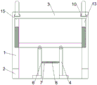
Fig. 1 is a schematic structural view of a scaffold for building construction.
Fig. 2 is a schematic structural diagram of a second bracket in the scaffold for building construction.
Fig. 3 is a schematic perspective view of an adjusting rod of a scaffold for building construction.
In the figure: 1. a first bracket; 2. a universal wheel; 3. a second bracket; 4. an auxiliary support; 5. cushion blocks; 6. a first spring; 7. a movable rod; 8. a bolt; 10. adjusting the bolt; 11. a handle; 12. a support plate; 13. adjusting a rod; 14. a sprocket; 15. a gear; 16. a rack; 17. a chain; 18. a reinforcing rod.
Detailed Description
The technical solutions in the embodiments of the present invention will be described clearly and completely with reference to the accompanying drawings in the embodiments of the present invention, and it is obvious that the described embodiments are only some embodiments of the present invention, not all embodiments. Based on the embodiments in the present invention, all other embodiments obtained by a person skilled in the art without creative work belong to the protection scope of the present invention.
Referring to fig. 1 to 3, in an embodiment of the present invention, a scaffold for building construction includes a first support 1 and a second support 3, the first support 1 is bilaterally symmetrical to each other, universal wheels 2 with brakes are installed on the lower side of the first support 1, reinforcing rods 18 are installed between the first supports 1, the reinforcing rods 18 are installed in a crossed manner, the stability of the first support 1 is enhanced by using the stability of a triangle, the second support 3 is located between the first supports 1, the second support 3 is fixed on the first support 1 in a shape of a Chinese character 'hui', the lower side of the second support 3 is hinged to two auxiliary supports 4, the auxiliary supports 4 are symmetrically arranged in a front-back manner, the lower sides of the auxiliary supports 4 are hinged to cushion blocks 5, the cushion blocks 5 and the auxiliary supports 4 form a triangle, the contact area is increased, the stability is improved, a first spring 6 is installed between the auxiliary supports 4, the first spring 6 is connected to a, the movable rod 7 is formed by sleeving two pipes, a plurality of through holes are formed in the sleeves, a bolt 8 is clamped in the through holes, the length of the movable rod 7 is adjusted through the bolt 8, the angle between the two auxiliary supports 4 is changed, and therefore the movable rod can better contact the ground, the front end and the rear end of the upper end of the second support 3 are connected with two adjusting rods 13 in a sliding mode, the upper end of each adjusting rod 13 is rotatably connected with an adjusting bolt 10, the adjusting bolt 10 is connected to the second support 3 in a threaded mode, the upper end of each adjusting bolt 10 is hinged to a handle 11, the handle 11 is formed by hinging three sections of straight rods, and the handle 11 at the end portion is sleeved with a rotating sleeve, so that the;
adjust pole 13's the montant left and right sides and support 1 and all be equipped with rack 16 towards both ends around one side of support two 3, rack 16 all meshes has gear 15, and gear 15 is coaxial to be equipped with sprocket 14, links to each other through chain 17 between the sprocket 14, and backup pad 12 is installed to the upside of rack 16, backup pad 12 includes frame all around and middle detachable joint board, and the left and right sides of joint board is equipped with fixed ear, and fixed ear joint is on the frame, and the protection network is connected through the protection network in the centre of joint board, forms work platform through backup pad 12, adjusts the position of pole 13 through rotating adjusting bolt 10, passes through gear 15 and sprocket 14 simultaneously, and the transmission drives backup pad 12 and reciprocates on support 1, reaches the purpose of adjusting.
The utility model discloses a theory of operation is: during the use, remove to the job site through universal wheel 2, adjust the angle that opens of two auxiliary stand 4 through movable rod 7, make cushion 5 sticis subaerial, the staff climbs and carries out the construction on backup pad 12, when the height of backup pad 12 is adjusted to needs, rotate handle 11, upwards rotate the regulation pole 13, drive rack 16 upward movement, thereby drive the transmission of chain 17, with backup pad 12 rebound, vice versa, make personnel can carry out quick regulation in backup pad 12, need not go down, the fine setting of backup pad 12 has been satisfied.
The utility model discloses a support 1 and auxiliary stand 4's supporting role is not limited to single thin four corners and supports, and the form of utilizing the middle land of propping improves stability, simultaneously, through adjusting bolt 10 and drive mechanism, the height of regulation backup pad 12 that can be convenient, easy operation, reliable and stable is applicable to the fine setting of table surface height.
The above, only be the concrete implementation of the preferred embodiment of the present invention, but the protection scope of the present invention is not limited thereto, and any person skilled in the art is in the technical scope of the present invention, according to the technical solution of the present invention and the utility model, the concept of which is equivalent to replace or change, should be covered within the protection scope of the present invention.
Claims (6)
1. A scaffold for building construction comprises a first support (1) and a second support (3), and is characterized in that the first support (1) is bilaterally symmetrically provided with two supports, universal wheels (2) with brakes are installed on the lower side of the first support (1), the second support (3) is located between the first supports (1), the second supports (3) are fixed on the first supports (1) in a shape like a Chinese character 'hui', the lower sides of the second supports (3) are hinged with two auxiliary supports (4), the auxiliary supports (4) are symmetrically arranged in the front and back direction, the lower sides of the auxiliary supports (4) are hinged with cushion blocks (5), a first spring (6) is arranged between the auxiliary supports (4), the first spring (6) is connected with a movable rod (7), the front end and the back end of the second support (3) are slidably connected with two adjusting rods (13), the upper ends of the adjusting rods (13) are rotatably connected with adjusting bolts (10), and the adjusting bolts (10), the upper end of the adjusting bolt (10) is hinged with a handle (11);
the utility model discloses a support of adjusting pole (13) is including adjusting pole (13) and support (1) and all being equipped with rack (16) towards both ends around one side of support two (3), and rack (16) all mesh has gear (15), and gear (15) are coaxial to be equipped with sprocket (14), link to each other through chain (17) between sprocket (14), and backup pad (12) are installed to the upside of rack (16).
2. A scaffold for building construction according to claim 1, characterized in that reinforcement rods (18) are installed between the first brackets (1), and the reinforcement rods (18) are installed in a cross way.
3. The scaffold for building construction according to claim 1, wherein the lower side of the spacer (5) is provided with a non-slip mat, and the spacer (5) and the auxiliary support (4) form a triangle.
4. The scaffold for building construction according to claim 1, wherein the movable rod (7) is formed by connecting two sleeves, and the sleeves are provided with a plurality of through holes, and the through holes are clamped with the bolts (8).
5. The scaffold for building construction as claimed in claim 1, wherein the handle (11) is formed by hinging three sections of straight rods, and a rotating sleeve is sleeved on the handle (11) at the end part.
6. The scaffold for building construction as claimed in claim 1, wherein the support plate (12) comprises a peripheral frame and a detachable clamping plate in the middle, the clamping plate is provided with fixing lugs at the left and right sides, the fixing lugs are clamped on the frame, and the middle of the clamping plate is connected through a protective net.
Priority Applications (1)
| Application Number | Priority Date | Filing Date | Title |
|---|---|---|---|
| CN202020174395.8U CN212201190U (en) | 2020-02-17 | 2020-02-17 | Scaffold for building construction |
Applications Claiming Priority (1)
| Application Number | Priority Date | Filing Date | Title |
|---|---|---|---|
| CN202020174395.8U CN212201190U (en) | 2020-02-17 | 2020-02-17 | Scaffold for building construction |
Publications (1)
| Publication Number | Publication Date |
|---|---|
| CN212201190U true CN212201190U (en) | 2020-12-22 |
Family
ID=73820716
Family Applications (1)
| Application Number | Title | Priority Date | Filing Date |
|---|---|---|---|
| CN202020174395.8U Expired - Fee Related CN212201190U (en) | 2020-02-17 | 2020-02-17 | Scaffold for building construction |
Country Status (1)
| Country | Link |
|---|---|
| CN (1) | CN212201190U (en) |
-
2020
- 2020-02-17 CN CN202020174395.8U patent/CN212201190U/en not_active Expired - Fee Related
Similar Documents
| Publication | Publication Date | Title |
|---|---|---|
| CN205171393U (en) | A formworking jumbo for arch culvert construction | |
| CN212201190U (en) | Scaffold for building construction | |
| CN205918078U (en) | Can dismantle mobile scaffold | |
| CN212105048U (en) | Construction lifting device for security engineering | |
| CN207377077U (en) | A kind of support construction of scaffold | |
| CN210622265U (en) | Building construction strutting arrangement | |
| CN211873797U (en) | Movable ladder stand protection device for folding and stretching scaffold | |
| CN208763385U (en) | A kind of architectural engineering scaffold | |
| CN201121405Y (en) | Adjustable Mobile Scaffolding | |
| CN211547401U (en) | Gate-type mound bent cap construction trolley | |
| CN213802471U (en) | Guardrail is overhauld in construction elevator installation | |
| CN209586241U (en) | A kind of mobile folding ladder | |
| CN211596310U (en) | Temporary construction platform for surface finishing in garden road construction process | |
| CN204609259U (en) | A kind of traveling stage | |
| CN213740597U (en) | Novel template support frame is used in public road bridge roof beam construction | |
| CN209179451U (en) | A building safety construction platform | |
| CN221001873U (en) | Folding scaffold for building construction | |
| CN210888758U (en) | Water conservancy is utilized and is overhauld cat ladder | |
| CN207829493U (en) | A kind of steel structure net rack supporting device for welding | |
| CN219909854U (en) | Adjustable operation platform for green construction | |
| CN220747591U (en) | Building construction platform convenient to remove | |
| CN204472420U (en) | Easy-to-mount combination easel | |
| CN217871679U (en) | A mobile and stable lifting scaffold | |
| CN218813202U (en) | A cast-in-place box girder construction support | |
| CN216767417U (en) | Platform is spread and hung to tunnel side wall waterproof board |
Legal Events
| Date | Code | Title | Description |
|---|---|---|---|
| GR01 | Patent grant | ||
| GR01 | Patent grant | ||
| CF01 | Termination of patent right due to non-payment of annual fee | ||
| CF01 | Termination of patent right due to non-payment of annual fee |
Granted publication date: 20201222 |