CN212242568U - A flow production device capable of continuous pad printing, lamination, punching and cutting of film materials - Google Patents
A flow production device capable of continuous pad printing, lamination, punching and cutting of film materials Download PDFInfo
- Publication number
- CN212242568U CN212242568U CN202020749889.4U CN202020749889U CN212242568U CN 212242568 U CN212242568 U CN 212242568U CN 202020749889 U CN202020749889 U CN 202020749889U CN 212242568 U CN212242568 U CN 212242568U
- Authority
- CN
- China
- Prior art keywords
- punching
- controller
- roller
- machine
- screen printing
- Prior art date
- Legal status (The legal status is an assumption and is not a legal conclusion. Google has not performed a legal analysis and makes no representation as to the accuracy of the status listed.)
- Expired - Fee Related
Links
Images


Landscapes
- Perforating, Stamping-Out Or Severing By Means Other Than Cutting (AREA)
Abstract
本实用新型一种膜材能够连续移印、覆膜、冲孔和裁切的流水生产装置涉及的是一种能够对柔性的膜材进行移印、覆膜、冲孔以及剪裁的生产设备。一种膜材能够连续移印、覆膜、冲孔和裁切流水生产装置,依次由放料平整机、丝印固化机、覆膜机、打孔机和裁切机连接而成,放料平整机、丝印固化机、覆膜机、打孔机和裁切机分别与控制器电连接,控制器还通过电源线与交流电源连接;其中放料平整机能够将套装在上面待移印的膜材进行拉伸;丝印固化机能够将放料平整机输送过来的膜材进行连续的移印,并利用固化灯进行固化;在膜材完成固化后,利用覆膜机贴覆保护膜;贴覆有保护膜后,利用打孔机对膜材进行打孔;利用裁切机裁剪成预定长度的膜材。
The utility model relates to a flow production device capable of continuous pad printing, lamination, punching and cutting of membrane materials, and relates to a production equipment capable of pad printing, lamination, punching and cutting of flexible membrane materials. A film material capable of continuous pad printing, lamination, punching and cutting flow production device, which is sequentially connected by an unloading leveling machine, a silk screen curing machine, a laminating machine, a punching machine and a cutting machine, and the unloading machine is smooth. The machine, screen printing curing machine, laminating machine, punching machine and cutting machine are respectively electrically connected to the controller, and the controller is also connected to the AC power supply through the power cord; the unwinding and levelling machine can set the film to be printed on it. The material is stretched; the screen printing curing machine can continuously pad and print the film conveyed by the unwinding and leveling machine, and use the curing lamp to cure; after the film is cured, use the laminating machine to cover the protective film; After the protective film is covered, the film material is punched by a punching machine; the film material of a predetermined length is cut by a cutting machine.
Description
技术领域technical field
本实用新型一种膜材能够连续移印、覆膜、冲孔和裁切流水生产装置涉及的是一种能够对柔性的膜材进行移印、覆膜、冲孔以及剪裁的生产设备。The utility model relates to a production device capable of continuous pad printing, lamination, punching and cutting of membrane materials, and relates to a production equipment capable of pad printing, lamination, punching and cutting of flexible membrane materials.
背景技术Background technique
在现在的包装材料中,具有图案的膜材包装材料具有良好的使用前景,为了进行更好的营销,为了产品显得更有档次以及能够清楚地对产品的内容进行广告宣传,往往需要在包装的膜材上印有相应的图案以及文字说明,但现有的膜材往往只是单纯的包装材料,所以有必要提供具有图案、文字的包装膜材,且膜材上的图案、文字不容易脱落;但现严重缺乏生产这种膜材的设备,所以有必要设计出一种能够满足大规模生产这种膜材的设备来满足实际的需求。In the current packaging materials, the film packaging materials with patterns have good prospects for use. In order to carry out better marketing, in order to make the products appear more advanced and to be able to clearly advertise the content of the products, it is often necessary to display the contents of the packaging. Corresponding patterns and text descriptions are printed on the film material, but the existing film material is often only a simple packaging material, so it is necessary to provide a packaging film material with patterns and words, and the patterns and words on the film material are not easy to fall off; But there is a serious lack of equipment for producing this kind of membrane material, so it is necessary to design a kind of equipment that can meet the large-scale production of this kind of membrane material to meet the actual demand.
实用新型内容Utility model content
本实用新型有鉴于此,提供了一种膜材能够连续移印、覆膜、冲孔和裁切流水生产装置,能够大规模地生产印有图案、文字的包装膜材,且这种包装膜材上的图案、文字由于有保护膜的存在,不容易被刮掉,具有良好的使用和推广价值。In view of this, the present utility model provides a film production device capable of continuous pad printing, film coating, punching and cutting, which can produce packaging films printed with patterns and characters on a large scale. Due to the existence of protective film, the patterns and characters on the stencil are not easy to be scratched off, and have good use and promotion value.
一种膜材能够连续移印、覆膜、冲孔和裁切流水生产装置,依次由放料平整机、丝印固化机、覆膜机、打孔机和裁切机连接而成,放料平整机、丝印固化机、覆膜机、打孔机和裁切机分别与控制器电连接,通过控制器发出的相应指令,能够控制对应设备的工作状态,控制器还通过电源线与交流电源连接;其中放料平整机能够将套装在上面待移印的膜材进行拉伸,并保持平整状态;丝印固化机能够将放料平整机输送过来的膜材进行连续的移印,并将移印好的图案、文字利用固化灯进行固化,防止移印的图案、文字脱落或变形;在膜材完成固化后,利用覆膜机将固化有图案、文字一面的膜材贴覆有一层保护膜;在贴覆有保护膜后,还能够根据需要,利用打孔机对膜材进行打孔,满足实际的使用需求;并在最后阶段,根据实际的需求,利用裁切机将膜材裁剪成预定长度的膜材。A film material capable of continuous pad printing, lamination, punching and cutting flow production device, which is sequentially connected by an unloading leveling machine, a silk screen curing machine, a laminating machine, a punching machine and a cutting machine, and the unloading machine is smooth. The machine, screen printing curing machine, laminating machine, punching machine and cutting machine are electrically connected to the controller respectively, and the corresponding commands issued by the controller can control the working status of the corresponding equipment, and the controller is also connected to the AC power supply through the power cord; Among them, the unwinding and leveling machine can stretch the film to be printed on it, and keep it in a flat state; the screen printing curing machine can continuously print the film conveyed by the unloading leveling machine, and transfer the film to the surface. The printed pattern and text are cured with a curing lamp to prevent the printed pattern and text from falling off or deformed; after the film is cured, the film with the pattern and text on one side is covered with a protective film by a laminating machine. ; After the protective film is attached, the film can also be punched by a punching machine as required to meet the actual use needs; and in the final stage, according to the actual needs, the film can be cut by a cutting machine. A predetermined length of film.
所述的控制器为工业计算机、PLC可编程控制器或单片机。The controller is an industrial computer, a PLC programmable controller or a single-chip microcomputer.
放料平整机,具有放料机架,在放料机架的下前方活动安装有气胀轴一,在放料机架上对应的位置固定安装有放料电机一,放料电机一通过输出轴与气胀轴一动力连接,气胀轴一用于放置待移印的绕卷膜材,在放料机架内的上部还安装有整平热辊;在整平热辊与气胀轴一之间还设置有导向辊一,用于气胀轴一放料时,能够更平稳地将膜材输送至整平热辊处;放料电机一、气胀轴一以及整平热辊分别与控制器电连接,通过控制器能够控制上述设备的工作状态。The discharge leveling machine has a discharge frame, an
所述的放料电机一为伺服电机,气胀轴一和整平热辊均为市售产品,其中整平热辊采用电加热,将待整平的膜材预热至预定温度,保证膜材在整平时的延展性一致,进而能够提高产品的一致性。The first discharging motor is a servo motor, and the first air-expansion shaft and the leveling hot roller are commercially available products. The leveling hot roller adopts electric heating to preheat the film material to be leveled to a predetermined temperature to ensure that the film The ductility of the material during leveling is consistent, which in turn improves product consistency.
所述的整平热辊,由上至下具有上辊一和下辊一;其中在放料机架上固定安装有整平电机,整平电机与下辊一动力连接,整平电机与控制器电连接,通过控制器能够控制整平电机的工作状态。The leveling hot roller has an
所述的整平电机为伺服电机。The leveling motor is a servo motor.
进一步地,位于下辊一的上方,在放料机架内固定安装有导向槽一,在导向槽一内放置有上辊一,上辊一两端的轴承与导向槽一内的矩形滑块固定连接,在导向槽一的上方安装有调距装置一。Further, it is located above the
所述的调距装置一为液压缸、行程气缸或压缩弹簧;在为液压缸、行程气缸时,液压缸、行程气缸的上端与导向槽一的顶端固定连接,尾端与矩形滑块固定连接,液压缸、行程气缸与控制器信号连接,通过控制器能够调节上辊一与下辊一之间的间距。The distance adjusting
丝印固化机,具有框架结构的丝印机架,在丝印机架的上表面具有托板,在丝印机架的侧面固定安装有安装机架,安装机架上活动安装有丝印组件,丝印组件位于托板的上方;在丝印机架上,位于托板的尾端安装有固化灯,固化灯被包裹在固化壳内;控制器分别与固化灯和丝印组件电连接,控制器能够对固化灯和丝印组件进行调控。Screen printing curing machine, a screen printing frame with a frame structure, a support plate on the upper surface of the screen printing frame, a mounting frame is fixedly installed on the side of the screen printing frame, and a screen printing assembly is movably installed on the mounting frame, and the screen printing assembly is located in the support. Above the board; on the screen printing frame, a curing lamp is installed at the tail end of the support plate, and the curing lamp is wrapped in the curing shell; the controller is electrically connected with the curing lamp and the screen printing component, and the controller can control the curing lamp and the screen printing assembly. components are regulated.
所述的安装机架内部的两侧具有垂直于水平面的滑槽,通过滑槽能够活动安装丝印组件;其中一侧的滑槽为凹槽,另一侧为镂空的通槽;在凹槽内契入滑块一,通槽内契入滑块二,在安装机架内部上方的两侧分别连接有等规格的牵引装置,牵引装置的另一端分别与滑块一和滑块二活动连接;牵引装置为液压缸或行程气缸,牵引装置与控制器信号连接,在控制器的指令下,牵引装置能够同步牵动滑块一和滑块二上下滑动,进而牵动丝印组件上下运动,滑块一和滑块二之间连接有两根互相平行的镜面的长杆,在滑块一和滑块二之间上还活动安装有一根丝杆,在安装机架上为通槽的滑槽处,安装有工字型的滑块二,滑块二的外侧面固定安装有横向驱动电机,横向驱动电机与控制器电连接,控制器能够发出指令控制横向驱动电机的工作状态,横向驱动电机的输出轴穿过滑块二上的通孔与丝杆动力连接;在长杆、丝杆上还套设有丝印活动座,其中与长杆为直接套接,与丝杆为通过滚珠轴承动力连接,横向驱动电机驱动丝杆转动,进而驱动丝印活动座左右移动;在丝印活动座的前方具有限位板,限位板上开设有两个等尺寸的限位孔,在限位孔内穿插有移动杆,移动杆的顶端固定连接有丝印头安装架,丝印活动座上方的后端固定安装有行程装置,行程装置的伸出端与移动杆的尾端固定连接,行程装置与控制器信号连接,通过控制器能够驱动行程装置上的伸出端前后运动,进而带动丝印头安装架前后移动,所述的行程装置为行程气缸或液压缸;在丝印头安装架的下方固定安装有伸缩装置,伸缩装置的下方固定连接有丝印头,伸缩装置与控制器信号连接;在丝印活动座的前下方固定安装有矩形的网板框,在网板框内铺设有有预设丝印内容的网板,网板能够与丝印头相配合。The two sides of the inside of the installation rack are provided with chute perpendicular to the horizontal plane, through which the silk screen components can be movably installed; the chute on one side is a groove, and the other side is a hollow through groove; in the groove The sliding
所述的伸缩装置为行程气缸或液压缸。The telescopic device is a stroke cylinder or a hydraulic cylinder.
进一步地,所述的滑块一,俯视方向剖面为T形,其中较小的一端插入滑槽内,较大端紧贴安装机架的内壁,起到限位作用,防止丝印组件在上下运动时脱落。Further, the
进一步地,在安装机架的底部还设置有与安装丝印组件配套的横向滑轨,用于在进行丝印时,丝印活动座的底部搁放在横向滑轨上,避免了丝杆、长杆由于重力造成的弯曲,进而造成丝印头在不同位置造成的丝印压力不一致,进而提高丝印的质量。Further, the bottom of the installation rack is also provided with a transverse slide rail matched with the installation screen printing assembly, so that the bottom of the screen printing movable seat is placed on the transverse slide rail when performing screen printing, so as to prevent the screw rod and the long rod from being caused by The bending caused by gravity will cause the screen printing pressure to be inconsistent at different positions of the screen printing head, thereby improving the quality of the screen printing.
所述的托板为钢化玻璃托板,用于能够检查观察丝印的质量。The support plate is a tempered glass support plate, which can be used to inspect and observe the quality of the silk screen.
在丝印机架上,位于托板的前方设置有输料托台一,用于提前托放膜材;在托板的两端还各设置有预整辊筒,预整辊筒由上辊筒和下辊筒通过支架固定安装在丝印机架上,使用时,膜材位于上辊筒和下辊筒之间,用于对膜材进行限位,防止膜材上下飘动,影响丝印;On the screen printing frame, there is a
覆膜机,具有覆膜机架,在覆膜机架的上前方活动安装有气胀轴二,在覆膜机架上对应的位置固定安装有放料电机二,放料电机二通过输出轴与气胀轴二动力连接,气胀轴二用于放置绕卷的保护层膜材,保护层膜材紧紧贴附在完成移印的膜材上表面,在覆膜机架内的上部还安装有热熔挤压辊;在热熔挤压辊与气胀轴二之间还设置有导向辊二,用于气胀轴二放料时,能够更平稳地将保护层膜材输送至热熔挤压辊处;放料电机二、气胀轴二以及热熔挤压辊分别与控制器电连接,通过控制器能够控制上述设备的工作状态。The laminating machine has a laminating frame, an
所述的放料电机二为伺服电机,气胀轴二和热熔挤压辊均为市售产品,其中热熔挤压辊采用电加热,将待覆膜的两层膜材预热至预定温度,保证膜材在较高的温度时进行贴合,保证保护层膜材贴附在完成移印膜材上的牢靠性。The second discharging motor is a servo motor, and the second air-expansion shaft and the hot-melt extrusion roller are commercially available products. The hot-melt extrusion roller adopts electric heating to preheat the two-layer film to be coated to a predetermined level. temperature, to ensure that the film is attached at a higher temperature, and to ensure the firmness of the protective layer film attached to the finished pad printing film.
所述的热熔挤压辊,由上至下具有上辊二和下辊二;其中在覆膜机架上固定安装有熔压电机,熔压电机与下辊二动力连接,熔压电机与控制器电连接,通过控制器能够控制熔压电机的工作状态。The hot-melt extrusion roller has two upper rollers and two lower rollers from top to bottom; wherein a melting pressure motor is fixedly installed on the laminating frame, and the melting pressure motor is powered with the second lower roller. The motor is electrically connected with the controller, and the controller can control the working state of the fusing motor.
所述的熔压电机为伺服电机。The melting pressure motor is a servo motor.
进一步地,位于下辊二的上方,在覆膜机架内固定固定安装有导向槽二,在导向槽二内放置有上辊二,上辊二两端的轴承与导向槽二内的矩形滑块固定连接,在导向槽二的上方安装有调距装置二。Further, it is located above the lower roller two, a guide groove two is fixed and fixed in the laminating frame, the upper roller two is placed in the guide groove two, the bearings at both ends of the upper roller two and the rectangular slider in the guide groove two For fixed connection, a distance adjusting
所述的调距装置二为液压缸、行程气缸或压缩弹簧;在为液压缸、行程气缸时,液压缸、行程气缸的上端与导向槽二的顶端固定连接,尾端与矩形滑块固定连接,液压缸、行程气缸与控制器信号连接,通过控制器能够调节上辊二与下辊二之间的间距。The second distance adjusting device is a hydraulic cylinder, a stroke cylinder or a compression spring; when it is a hydraulic cylinder or a stroke cylinder, the upper end of the hydraulic cylinder and the stroke cylinder are fixedly connected to the top of the second guide groove, and the tail end is fixedly connected to the rectangular slider. , The hydraulic cylinder and the stroke cylinder are connected with the signal of the controller, and the distance between the second upper roller and the second lower roller can be adjusted through the controller.
打孔机,具有打孔机架,在打孔机架的上方设置有左右对称的打孔安装座,在打孔安装座之间固定安装有多根相互平行的导向杆,并活动安装有一根滚珠丝杠,滚珠丝杠与导向杆平行,同时在一侧的打孔安装座上还固定安装有滚珠丝杠驱动电机,滚珠丝杠驱动电机与滚珠丝杠动力连接,滚珠丝杠驱动电机与控制器电连接,在导向杆和滚珠丝杠上套装有冲刀座,冲刀座上穿过导向杆的通孔为镜面孔,穿过滚珠丝杠的通孔为螺纹孔;冲刀座上安装有行程气缸或液压缸,行程气缸或液压缸与控制器信号连接,在行程气缸或液压缸的底端安装有用于对膜材进行冲孔的冲刀;在打孔机架上,位于冲刀座的下方固定安装有冲孔底座,在冲孔底座上开设有与冲刀相配合的冲孔,使用时,冲刀将膜材冲出孔洞,并伸入至冲孔内。The punching machine has a punching rack, and a left-right symmetrical punching mounting seat is arranged above the punching rack. A plurality of guide rods parallel to each other are fixedly installed between the punching mounting seats, and one is movably installed. The ball screw is parallel to the guide rod. At the same time, a ball screw drive motor is also fixedly installed on the drilling mounting seat on one side. The ball screw drive motor is powered with the ball screw, and the ball screw drive motor is connected to The controller is electrically connected, and a punching knife seat is set on the guide rod and the ball screw, the through hole passing through the guiding rod on the punching knife seat is a mirror hole, and the through hole passing through the ball screw is a threaded hole; A stroke cylinder or hydraulic cylinder is installed, the stroke cylinder or hydraulic cylinder is connected with the signal of the controller, and a punching knife for punching the membrane material is installed at the bottom end of the stroke cylinder or hydraulic cylinder; A punching base is fixedly installed under the knife seat, and a punching hole matched with the punching knife is opened on the punching base. When in use, the punching knife punches the film material out of the hole and extends into the punching hole.
所述的冲孔为贯通的通孔,在打孔机架的下方,设置有收集桶,用于收集冲刀冲下的碎屑。The punching hole is a through hole, and a collecting bucket is arranged below the punching frame for collecting the debris punched by the punching knife.
在冲刀座上还能够安装有摄像头,摄像头与控制器信号连接,通过摄像头能够实时检测冲刀在冲孔时是否对准,提高冲孔的质量;所述的摄像头优选为微距摄像头。A camera can also be installed on the punching knife seat, and the camera is connected with the signal of the controller. The camera can detect in real time whether the punching knife is aligned during punching, and improve the quality of punching; the camera is preferably a macro camera.
所述的冲孔底座为金属板材或平面的橡胶板,优选为橡胶板,用于防止冲刀在故障情况下冲压至冲孔底座上,防止冲刀折断。The punching base is a metal plate or a flat rubber plate, preferably a rubber plate, which is used to prevent the punching knife from being punched onto the punching base in the event of a failure and prevent the punching knife from breaking.
在打孔安装座的前后侧还分别安装有整平冷辊;整平冷辊由上至下具有上辊三和下辊三;上辊三和下辊三通过支柱固定安装在打孔安装座上,上辊三和下辊三之间具有让膜材通过的间隙。Leveling chill rolls are also installed on the front and rear sides of the perforated mounting seat respectively; the leveling chill roll has three upper rolls and three lower rolls from top to bottom; the three upper rolls and the three lower rolls are fixedly installed on the perforated mounting seat through pillars There is a gap for the film material to pass between the upper, upper and lower rollers 3 and 3.
进一步地,在整平冷辊一侧的支柱上安装有整平冷辊驱动电机,整平冷辊驱动电机的输出轴与上辊三或下辊三动力连接,整平冷辊驱动电机与控制器信号连接。Further, a leveling chill roll drive motor is installed on the pillar on one side of the leveling chill roll, the output shaft of the levelling chill roll drive motor is connected to the upper roll 3 or the lower roll 3 with power, and the leveling chill roll drive motor is connected to the control unit. signal connection.
所述的整平冷辊驱动电机为伺服电机。The leveling chill roller drive motor is a servo motor.
在打孔安装座上,分别位于整平冷辊的外侧设置有输料托台二,用于托放膜材。On the perforated mounting seat, there are two feeding trays respectively located on the outer sides of the leveling chill rolls, which are used for supporting and placing film materials.
在打孔机架的上方设置有罩壳,使用罩壳能够将打孔机架上的所有设备,包含打孔安装座、导向杆、滚珠丝杠和冲刀座包含在内,用以提供保护。A cover is arranged above the punching rack, and all the equipment on the punching rack, including the punching mounting seat, guide rod, ball screw and punching tool seat, can be contained by using the cover to provide protection .
裁切机,具有裁切机架,在裁切机架的上表面铺设有台板,在台板的前方固定安装有裁切组件,裁切组件后方活动安装有配套的拉料组件,裁切组件用于将膜材裁切成预定长度的膜材片,拉料组件用于牵引被裁切的膜材,并将裁切好的膜材拖动至预定的叠放位置。The cutting machine has a cutting frame, a platen is laid on the upper surface of the cutting frame, a cutting assembly is fixedly installed in front of the platen, and a supporting material pulling assembly is movably installed behind the cutting assembly. The assembly is used to cut the film into predetermined lengths of film sheets, and the pulling assembly is used to pull the cut film and drag the cut film to a predetermined stacking position.
所述的裁切组件具有支撑柱,在支撑柱上安装有送料辊,送料辊的后方活动安装有裁切刀架,裁切刀架的下方安装有条状的切刀,裁切刀架与裁切机架之间安装有行程气缸或液压缸,行程气缸或液压缸与控制器信号连接,在控制器的指令下行程气缸或液压缸能够驱动裁切刀架,并带动切刀上下运动,从而能够完成膜材的切割。The cutting assembly has a support column, a feeding roller is installed on the supporting column, a cutting knife holder is movably installed at the rear of the feeding roller, and a strip-shaped cutter is installed under the cutting knife holder, and the cutting knife holder is connected with the cutting tool holder. A stroke cylinder or hydraulic cylinder is installed between the cutting frames. The stroke cylinder or hydraulic cylinder is connected with the signal of the controller. Under the command of the controller, the stroke cylinder or hydraulic cylinder can drive the cutting knife frame and drive the cutting knife to move up and down. Thus, the cutting of the film material can be completed.
所述的送料辊由上至下具有上辊四和下辊四;上辊四固定安装在支撑柱上,上辊四和下辊四之间具有让膜材通过的间隙。The feeding roller has four upper rollers and four lower rollers from top to bottom; the four upper rollers are fixedly installed on the support column, and there is a gap between the four upper rollers and the four lower rollers for the film material to pass through.
进一步地,位于下辊四的上方,在支撑柱的内侧固定固定安装有导向槽四,在导向槽四内放置有上辊四,上辊四两端的轴承与导向槽四内的矩形滑块固定连接,在导向槽四的上方安装有调距装置四。Further, it is located above the
所述的调距装置四为液压缸、行程气缸或压缩弹簧;在为液压缸、行程气缸时,液压缸、行程气缸的上端与导向槽四的顶端固定连接,尾端与矩形滑块固定连接,液压缸、行程气缸与控制器信号连接,通过控制器能够调节上辊四与下辊四之间的间距。The
进一步地,在一侧的支撑柱上安装有送料驱动电机,送料驱动电机的输出轴与下辊四动力连接,送料驱动电机与控制器信号连接。Further, a feeding driving motor is installed on one side of the support column, the output shaft of the feeding driving motor is connected with the power of the lower roller, and the feeding driving motor is signally connected with the controller.
所述的送料驱动电机为伺服电机。The feeding drive motor is a servo motor.
所述的拉料组件,具有门形的拉料架,拉料架活动安放在拉料滑轨上,在拉料架上安装有行程气缸或液压缸,行程气缸或液压缸的尾端连接有吸盘支架,在吸盘支架上安装有气动吸盘,气动吸盘、行程气缸或液压缸分别与控制器信号连接,通过控制器能够进行相应的动作。The pulling material assembly has a door-shaped pulling material frame, the pulling material frame is movably placed on the pulling material sliding rail, a stroke cylinder or a hydraulic cylinder is installed on the pulling material frame, and the tail end of the stroke cylinder or the hydraulic cylinder is connected with a The suction cup bracket is equipped with a pneumatic suction cup, the pneumatic suction cup, the stroke cylinder or the hydraulic cylinder are respectively connected with the signal of the controller, and the corresponding action can be performed through the controller.
进一步地,在拉料架上,位于行程气缸或液压缸的两侧分别设置有限位孔,在吸盘支架的上方设置有限位杆,限位杆插入限位孔内,保证行程气缸或液压缸运动时,不超出预定的角度范围。Further, on the material pulling frame, limit holes are arranged on both sides of the stroke cylinder or hydraulic cylinder, and a limit rod is set above the suction cup bracket, and the limit rod is inserted into the limit hole to ensure the movement of the stroke cylinder or the hydraulic cylinder. , does not exceed the predetermined angle range.
所述的气动吸盘数量为2-5个,优选为2-3个。The number of the pneumatic suction cups is 2-5, preferably 2-3.
在裁切机架上能够安装有防尘隔音罩,防尘隔音罩通过卡扣、螺栓或焊接与台板固定连接,并将台板上方的所有部件包含在内,用以隔绝裁切中产生的噪音,并便于维护。A dust-proof and sound-proof cover can be installed on the cutting frame. The dust-proof and sound-proof cover is fixedly connected to the platen by means of clips, bolts or welding, and includes all the parts above the platen to isolate the noise generated during cutting. noise and easy maintenance.
本实用新型一种膜材能够连续移印、覆膜、冲孔和裁切流水生产装置的使用方法如下:The use method of the film material of the utility model capable of continuous pad printing, film coating, punching and cutting flow production device is as follows:
(1).接通电源,在控制器上设置好相应的参数,将待加工的呈绕卷状态的膜材放置在放料平整机的气胀轴一上;(1). Turn on the power supply, set the corresponding parameters on the controller, and place the film material to be processed in a rolled state on the air expansion shaft of the unwinding leveler;
(2).放料平整机将套装在上面待移印的膜材进行拉伸,并保持平整状态;(2). The unwinding and leveling machine stretches the film material that is set on it to be printed, and keeps it in a flat state;
(3).丝印固化机将放料平整机输送过来的膜材进行连续的移印,并将移印好的图案、文字利用固化灯进行固化,防止移印的图案、文字脱落或变形;(3). The screen printing curing machine continuously pad-prints the film conveyed by the unloading and leveling machine, and uses the curing lamp to cure the printed pattern and text to prevent the printed pattern and text from falling off or deforming;
(4).在膜材完成固化后,利用覆膜机将固化有图案、文字一面的膜材贴覆有一层保护膜;(4). After the film material is cured, use a laminating machine to cover the film material with the pattern and text on the cured side with a protective film;
(5).在贴覆有保护膜后,利用打孔机对膜材进行打孔;(5). After the protective film is attached, use a punching machine to punch holes in the film;
(6).最后利用裁切机将膜材裁剪成预定长度的膜材。(6). Finally, the film material is cut into a predetermined length of film material by a cutting machine.
一种膜材能够连续移印、覆膜、冲孔和裁切流水生产装置中放料平整机的具体工作方法为:A specific working method of a discharge leveling machine in a production device capable of continuous pad printing, lamination, punching and cutting of film materials is as follows:
在接通电源,在控制器上设置好相应的参数后,将待加工的呈绕卷状态的膜材放置在放料平整机的气胀轴一上;After the power is turned on and the corresponding parameters are set on the controller, the film material to be processed in a rolled state is placed on the
拉伸出的膜材通过导向辊一进行张紧,并穿过整平热辊的上辊一和下辊一之间的间隙内,并压紧;The stretched film is tensioned by the
与整平热辊动力连接的放料电机一驱动上辊一和下辊一进行对转,进而将膜材进行拉伸,绷紧;并将整平好的膜材输送至丝印固化机内。The discharge motor connected with the power of the leveling hot roller drives the upper roller and the lower roller to rotate in opposite directions, thereby stretching and tightening the film material; and transporting the leveled film material to the screen printing curing machine.
一种膜材能够连续移印、覆膜、冲孔和裁切流水生产装置中丝印固化机的具体工作方法为:A specific working method of a screen printing curing machine in a production device capable of continuous pad printing, lamination, punching and cutting of film materials is as follows:
整平好的膜材通过预整辊筒输送至托板上;牵引装置同步牵引滑块一和滑块二向下运动,进而牵引丝印组件向下运动;The leveled film is transported to the pallet through the pre-leveling roller; the traction device synchronously pulls the
丝印组件的下方接触至横向滑轨时停止运动;When the bottom of the silk screen assembly touches the horizontal rail, it stops moving;
丝印活动座下方的网板框贴覆在膜材的上方;The screen frame under the screen printing movable seat is pasted on the top of the membrane;
行程装置驱动丝印活动座向前运动;The travel device drives the screen printing movable seat to move forward;
伸缩装置驱动丝印头贴合至网板框上的网板上;The telescopic device drives the screen printing head to attach to the screen on the screen frame;
横向驱动电机驱动丝印活动座左右运动,进而带动丝印头在网板框内运动,进而完成丝印动作;The lateral drive motor drives the screen printing movable seat to move left and right, and then drives the screen printing head to move in the screen frame, thereby completing the screen printing action;
伸缩装置驱动丝印头和网板框抬升;The telescopic device drives the screen printing head and the screen frame to lift;
丝印好的膜材被输送至固化灯处进行丝印内容的固化;The screen-printed film is transported to the curing lamp for curing of the screen-printed content;
将固化好的膜材输送至覆膜机处,同时对下一段膜材进行丝印和固化,如此周而往复。The cured film material is conveyed to the laminating machine, and the next film material is screen-printed and cured at the same time, and so on.
一种膜材能够连续移印、覆膜、冲孔和裁切流水生产装置中覆膜机的具体工作方法为:A specific working method of a laminating machine in a production device capable of continuous pad printing, lamination, punching and cutting of film materials is as follows:
在气胀轴二上套设起保护作用的保护膜;A protective film for protection is sleeved on the second inflatable shaft;
将完成丝印和固化的膜材输送至覆膜机架上,在导向辊二的贴合下,保护膜和膜材的上表面进行贴合;The screen-printed and cured film is transported to the laminating frame, and under the bonding of the guide roller two, the protective film and the upper surface of the film are bonded;
将保护膜和膜材同步送入热熔挤压辊中上辊二和下辊二之间的间隙内,并进行压紧和热熔;The protective film and the film material are simultaneously fed into the gap between the
熔压电机驱动发热的上辊二和下辊二进行对转,进而将保护膜和膜材紧紧压在一起。The melting pressure motor drives the heated
一种膜材能够连续移印、覆膜、冲孔和裁切流水生产装置中打孔机的具体工作方法为:A specific working method of a punching machine in a production device capable of continuous pad printing, lamination, punching and cutting of film materials is as follows:
将覆膜机中完成覆膜的膜材输送至打孔机架上;Transport the film material that has been covered in the film laminator to the punching rack;
膜材送入整平冷辊中上辊三和下辊三之间的间隙内,整平冷辊驱动电机驱动上辊三和下辊三进行对转,将膜材输送至冲孔底座上;The film material is fed into the gap between the upper roll 3 and the lower roll 3 in the leveling chill roll, and the driving motor of the leveling chill roll drives the upper roll 3 and the lower roll 3 to rotate in opposite directions, and transports the film material to the punching base;
摄像头在检测到膜材后,控制器发出指令,驱动滚珠丝杠驱动电机将冲刀座横向运动至预定位置;After the camera detects the film, the controller sends an instruction to drive the ball screw drive motor to move the punching seat laterally to a predetermined position;
控制器发出指令,冲刀向下冲动,将膜材冲出相应的通孔,并在完成冲孔后,向上拔出冲刀。The controller issues an instruction, and the punching knife urges downward to punch the film material out of the corresponding through hole, and after the punching is completed, the punching knife is pulled upwards.
一种膜材能够连续移印、覆膜、冲孔和裁切流水生产装置中裁切机的具体工作方法为:A specific working method of a cutting machine in a production device capable of continuous pad printing, lamination, punching and cutting of film materials is as follows:
将完成冲孔的膜材输入至送料辊上的上辊四和下辊四之间的间隙内;Input the punched film material into the gap between the
裁切刀架上的切刀在行程气缸或液压缸的驱动下,向下运动,将膜材切断;Driven by the stroke cylinder or hydraulic cylinder, the cutter on the cutting knife holder moves downward to cut off the film;
拉料组件上的气动吸盘在行程气缸或液压缸的驱动下,向下吸取切好的膜材;Driven by the stroke cylinder or hydraulic cylinder, the pneumatic suction cup on the pulling component sucks the cut film downwards;
吸取好膜材后,将膜材向后拉动,码放在预定的位置即可。After sucking the film material, pull the film material back and place it in the predetermined position.
本实用新型一种膜材能够连续移印、覆膜、冲孔和裁切流水生产装置中裁切机构思巧妙、使用方便,加工的自动化程度好,进而加工效率高,具有良好的使用和推广效果。The film material of the utility model is capable of continuous pad printing, film coating, punching and cutting. The cutting mechanism in the production device is ingenious in design, convenient to use, and has a high degree of automation in processing, thereby high processing efficiency and good use and promotion effects. .
附图说明Description of drawings
为了使本实用新型的目的、技术方案和优点更加清楚,下面结合附图对本实用新型予以进一步说明:In order to make the purpose, technical solutions and advantages of the present utility model clearer, the present utility model will be further described below in conjunction with the accompanying drawings:
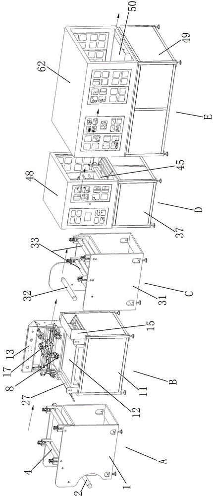
图1为本实用新型一种膜材能够连续移印、覆膜、冲孔和裁切流水生产装置的立体结构示意图。FIG. 1 is a schematic three-dimensional structure diagram of a production device for continuous pad printing, lamination, punching and cutting of a film material according to the present invention.
图2为本实用新型一种膜材能够连续移印、覆膜、冲孔和裁切流水生产装置的主视结构示意图。FIG. 2 is a schematic front view of the structure of a production device for continuous pad printing, lamination, punching and cutting of film materials according to the present invention.
图3为本实用新型一种膜材能够连续移印、覆膜、冲孔和裁切流水生产装置中放料平整机的立体结构示意图。FIG. 3 is a schematic three-dimensional structure diagram of a discharge leveling machine in a production device for continuous pad printing, lamination, punching and cutting of film materials according to the present invention.
图4为本实用新型一种膜材能够连续移印、覆膜、冲孔和裁切流水生产装置中丝印固化机的立体结构示意图。FIG. 4 is a schematic three-dimensional structure diagram of a screen printing curing machine in a production device for continuous pad printing, film coating, punching and cutting of a film material according to the present invention.
图5为本实用新型一种膜材能够连续移印、覆膜、冲孔和裁切流水生产装置中覆膜机的立体结构示意图。FIG. 5 is a schematic three-dimensional structure diagram of a laminating machine in a production device for continuous pad printing, lamination, punching and cutting of membrane materials according to the present invention.
图6为本实用新型一种膜材能够连续移印、覆膜、冲孔和裁切流水生产装置中打孔机的立体结构示意图一(含罩壳)。FIG. 6 is a first three-dimensional structural schematic diagram (including a cover) of a punching machine in a production device for continuous pad printing, lamination, punching and cutting of a film material according to the present invention.
图7为本实用新型一种膜材能够连续移印、覆膜、冲孔和裁切流水生产装置中打孔机的立体结构示意图二(去除罩壳)。Fig. 7 is a schematic diagram 2 of the three-dimensional structure of a punching machine in a flow production device capable of continuous pad printing, lamination, punching and cutting of a film material of the present invention (with the cover removed).
图8为本实用新型一种膜材能够连续移印、覆膜、冲孔和裁切流水生产装置中打孔机的冲刀座的结构示意图。8 is a schematic structural diagram of a punching knife seat of a punching machine in a production device for continuous pad printing, lamination, punching and cutting of a film material according to the present invention.
图9为本实用新型一种膜材能够连续移印、覆膜、冲孔和裁切流水生产装置中裁切机的立体结构示意图(去除防尘隔音罩)。9 is a schematic diagram of the three-dimensional structure of a cutting machine in a production device for continuous pad printing, lamination, punching and cutting of film materials according to the present invention (with the dustproof and soundproof cover removed).
具体实施方式Detailed ways
以下将结合附图,对本实用新型一种膜材能够连续移印、覆膜、冲孔和裁切流水生产装置作进一步说明。The following will further describe a production device of the present invention that can continuously pad printing, film, punch and cut a film material in conjunction with the accompanying drawings.
参照附图1-9,一种膜材能够连续移印、覆膜、冲孔和裁切流水生产装置,依次由放料平整机A、丝印固化机B、覆膜机C、打孔机D和裁切机E连接而成,放料平整机A、丝印固化机B、覆膜机C、打孔机D和裁切机E分别与控制器电连接,通过控制器发出的相应指令,能够控制对应设备的工作状态,控制器还通过电源线与交流电源连接;其中放料平整机A能够将套装在上面待移印的膜材进行拉伸,并保持平整状态;丝印固化机B能够将放料平整机A输送过来的膜材进行连续的移印,并将移印好的图案、文字利用固化灯进行固化,防止移印的图案、文字脱落或变形;在膜材完成固化后,利用覆膜机C将固化有图案、文字一面的膜材贴覆有一层保护膜;在贴覆有保护膜后,还能够根据需要,利用打孔机D对膜材进行打孔,满足实际的使用需求;并在最后阶段,根据实际的需求,利用裁切机E将膜材裁剪成预定长度的膜材。Referring to the accompanying drawings 1-9, a film material capable of continuous pad printing, lamination, punching and cutting flow production device, which is sequentially composed of a discharging and leveling machine A, a silk screen curing machine B, a laminating machine C, and a punching machine D. It is connected with the cutting machine E. The unwinding and leveling machine A, the silk screen curing machine B, the laminating machine C, the punching machine D and the cutting machine E are respectively electrically connected with the controller, and can be controlled by the corresponding instructions issued by the controller. Corresponding to the working state of the equipment, the controller is also connected to the AC power supply through the power cord; the unwinding and leveling machine A can stretch the film to be printed on it, and keep it in a flat state; the silk-screen curing machine B can The film conveyed by the unwinding and leveling machine A is continuously pad-printed, and the printed patterns and characters are cured with a curing lamp to prevent the printed patterns and characters from falling off or deformed; after the film is cured, Use laminating machine C to stick a layer of protective film on the cured film with patterns and characters on one side; after sticking the protective film, punching machine D can be used to perforate the film according to actual needs. Use demand; and in the final stage, according to the actual demand, use the cutting machine E to cut the film material into a predetermined length of film material.
所述的控制器为工业计算机、PLC可编程控制器或单片机。The controller is an industrial computer, a PLC programmable controller or a single-chip microcomputer.
参照附图1、附图2和附图3,放料平整机A,具有放料机架1,在放料机架1的下前方活动安装有气胀轴一2,在放料机架1上对应的位置固定安装有放料电机一3,放料电机一3通过输出轴与气胀轴一2动力连接,气胀轴一2用于放置待移印的绕卷膜材,在放料机架1内的上部还安装有整平热辊4;在整平热辊4与气胀轴一2之间还设置有导向辊一5,用于气胀轴一2放料时,能够更平稳地将膜材输送至整平热辊4处;放料电机一3、气胀轴一2以及整平热辊4分别与控制器电连接,通过控制器能够控制上述设备的工作状态。Referring to Figure 1, Figure 2 and Figure 3, the unloading leveling machine A has a
所述的放料电机一为伺服电机,气胀轴一和整平热辊均为市售产品,其中整平热辊采用电加热,将待整平的膜材预热至预定温度,保证膜材在整平时的延展性一致,进而能够提高产品的一致性。The first discharging motor is a servo motor, and the first air-expansion shaft and the leveling hot roller are commercially available products. The leveling hot roller adopts electric heating to preheat the film material to be leveled to a predetermined temperature to ensure that the film The ductility of the material during leveling is consistent, which in turn improves product consistency.
所述的整平热辊4,由上至下具有上辊一4-1和下辊一4-2;其中在放料机架1上固定安装有整平电机6,整平电机6与下辊一4-2动力连接,整平电机6与控制器电连接,通过控制器能够控制整平电机6的工作状态。The leveling
所述的整平电机6为伺服电机。The leveling
进一步地,位于下辊一4-2的上方,在放料机架1内固定安装有导向槽一7,在导向槽一7内放置有上辊一4-1,上辊一4-1两端的轴承与导向槽一7内的矩形滑块7-1固定连接,在导向槽一7的上方安装有调距装置一8。Further, located above the lower roller one 4-2, a guide groove one 7 is fixedly installed in the discharging
所述的调距装置一8为液压缸、行程气缸或压缩弹簧;在为液压缸、行程气缸时,液压缸、行程气缸的上端与导向槽一7的顶端固定连接,尾端与矩形滑块7-1固定连接,液压缸、行程气缸与控制器信号连接,通过控制器能够调节上辊一4-1与下辊一4-2之间的间距。The
参照附图1、附图2和附图4,丝印固化机B,具有框架结构的丝印机架11,在丝印机架11的上表面具有托板12,在丝印机架11的侧面固定安装有安装机架13,安装机架13上活动安装有丝印组件,丝印组件位于托板12的上方;在丝印机架上,位于托板12的尾端安装有固化灯14,固化灯14被包裹在固化壳15内;控制器分别与固化灯14和丝印组件电连接,控制器能够对固化灯14和丝印组件进行调控。Referring to FIG. 1 , FIG. 2 and FIG. 4 , the screen printing curing machine B has a
所述的安装机架13内部的两侧具有垂直于水平面的滑槽,通过滑槽能够活动安装丝印组件;其中一侧的滑槽为凹槽,另一侧为镂空的通槽16;在凹槽内契入滑块一17,通槽内契入滑块二18,在安装机架13内部上方的两侧分别连接有等规格的牵引装置61,牵引装置61的另一端分别与滑块一17和滑块二18活动连接;牵引装置61为液压缸或行程气缸,牵引装置61与控制器信号连接,在控制器的指令下,牵引装置61能够同步牵动滑块一17和滑块二18上下滑动,进而牵动丝印组件上下运动,滑块一17和滑块二18之间连接有两根互相平行的镜面的长杆19,在滑块一17和滑块二18之间上还活动安装有一根丝杆20,在安装机架13上为通槽16的滑槽处,安装有工字型的滑块二18,滑块二18的外侧面固定安装有横向驱动电机21,横向驱动电机21与控制器电连接,控制器能够发出指令控制横向驱动电机21的工作状态,横向驱动电机21的输出轴穿过滑块二18上的通孔与丝杆20动力连接;在长杆19、丝杆20上还套设有丝印活动座22,其中与长杆19为直接套接,与丝杆20为通过滚珠轴承动力连接,横向驱动电机21驱动丝杆20转动,进而驱动丝印活动座22左右移动;在丝印活动座22的前方具有限位板22-1,限位板22-1上开设有两个等尺寸的限位孔,在限位孔内穿插有移动杆22-2,移动杆22-2的顶端固定连接有丝印头安装架24,丝印活动座22上方的后端固定安装有行程装置23,行程装置23的伸出端与移动杆22-2的尾端固定连接,行程装置23与控制器信号连接,通过控制器能够驱动行程装置23上的伸出端前后运动,进而带动丝印头安装架24前后移动,所述的行程装置23为行程气缸或液压缸;在丝印头安装架24的下方固定安装有伸缩装置25,伸缩装置25的下方固定连接有丝印头8,伸缩装置25与控制器信号连接;在丝印活动座22的前下方固定安装有矩形的网板框9,在网板框9内铺设有有预设丝印内容的网板,网板能够与丝印头8相配合。The two sides inside the
所述的伸缩装置25为行程气缸或液压缸。The
进一步地,所述的滑块一17,俯视方向剖面为T形,其中较小的一端插入滑槽内,较大端紧贴安装机架13的内壁,起到限位作用,防止丝印组件在上下运动时脱落。Further, the sliding block one 17 has a T-shaped cross section in the top view direction, wherein the smaller end is inserted into the chute, and the larger end is close to the inner wall of the
进一步地,在安装机架13的底部还设置有与安装丝印组件配套的横向滑轨10,用于在进行丝印时,丝印活动座22的底部搁放在横向滑轨10上,避免了丝杆20、长杆19由于重力造成的弯曲,进而造成丝印头8在不同位置造成的丝印压力不一致,进而提高丝印的质量。Further, the bottom of the
所述的托板12为钢化玻璃托板,用于能够检查观察丝印的质量。The supporting
在丝印机架11上,位于托板12的前方设置有输料托台一26,用于提前托放膜材;在托板12的两端还各设置有预整辊筒27,预整辊筒27由上辊筒27-1和下辊筒27-2通过支架固定安装在丝印机架11上,使用时,膜材位于上辊筒27-1和下辊筒27-2之间,用于对膜材进行限位,防止膜材上下飘动,影响丝印;On the
参照附图1、附图2和附图5,覆膜机C,具有覆膜机架31,在覆膜机架31的上前方活动安装有气胀轴二32,在覆膜机架31上对应的位置固定安装有放料电机二30,放料电机二30通过输出轴与气胀轴二32动力连接,气胀轴二32用于放置绕卷的保护层膜材,保护层膜材紧紧贴附在完成移印的膜材上表面,在覆膜机架31内的上部还安装有热熔挤压辊33;在热熔挤压辊33与气胀轴二32之间还设置有导向辊二34,用于气胀轴二32放料时,能够更平稳地将保护层膜材输送至热熔挤压辊33处;放料电机二30、气胀轴二32以及热熔挤压辊33分别与控制器电连接,通过控制器能够控制上述设备的工作状态。Referring to Figure 1, Figure 2 and Figure 5, the laminating machine C has a
所述的放料电机二30为伺服电机,气胀轴二32和热熔挤压辊33均为市售产品,其中热熔挤压辊33采用电加热,将待覆膜的两层膜材预热至预定温度,保证膜材在较高的温度时进行贴合,保证保护层膜材贴附在完成移印膜材上的牢靠性。The second discharging
所述的热熔挤压辊33,由上至下具有上辊二33-1和下辊二33-2;其中在覆膜机架31上固定安装有熔压电机35,熔压电机35与下辊二33-2动力连接,熔压电机35与控制器电连接,通过控制器能够控制熔压电机35的工作状态。The hot-melt extrusion roller 33 has two upper rollers 33-1 and two lower rollers 33-2 from top to bottom; wherein the
所述的熔压电机35为伺服电机。The
进一步地,位于下辊二33-2的上方,在覆膜机架31内固定固定安装有导向槽二31-1,在导向槽二31-1内放置有上辊二33-1,上辊二33-1两端的轴承与导向槽二31-1内的矩形滑块固定连接,在导向槽二31-1的上方安装有调距装置二33-2。Further, located above the second lower roller 33-2, a guide groove two 31-1 is fixedly installed in the
所述的调距装置二36为液压缸、行程气缸或压缩弹簧;在为液压缸、行程气缸时,液压缸、行程气缸的上端与导向槽二31-1的顶端固定连接,尾端与矩形滑块固定连接,液压缸、行程气缸与控制器信号连接,通过控制器能够调节上辊二33-1与下辊二33-2之间的间距。The
参照附图1、附图2、附图6、附图7和附图8,打孔机D,具有打孔机架37,在打孔机架37的上方设置有左右对称的打孔安装座38,在打孔安装座38之间固定安装有多根相互平行的导向杆39,并活动安装有一根滚珠丝杠40,滚珠丝杠40与导向杆39平行,同时在一侧的打孔安装座38上还固定安装有滚珠丝杠驱动电机41,滚珠丝杠驱动电机41与滚珠丝杠40动力连接,滚珠丝杠驱动电机41与控制器电连接,在导向杆39和滚珠丝杠40上套装有冲刀座42,冲刀座42上穿过导向杆39的通孔为镜面孔39-1,穿过滚珠丝杠40的通孔为螺纹孔40-1;冲刀座42上安装有行程气缸或液压缸42-1,行程气缸或液压缸42-1与控制器信号连接,在行程气缸或液压缸42-1的底端安装有用于对膜材进行冲孔的冲刀42-2;在打孔机架37上,位于冲刀座42的下方固定安装有冲孔底座43,在冲孔底座43上开设有与冲刀42-2相配合的冲孔,使用时,冲刀42-2将膜材冲出孔洞,并伸入至冲孔43-1内。Referring to Figure 1, Figure 2, Figure 6, Figure 7 and Figure 8, the punching machine D has a punching
所述的冲孔43-1为贯通的通孔,在打孔机架37的下方,设置有收集桶,用于收集冲刀42-2冲下的碎屑。The punching hole 43-1 is a through hole. Below the punching
在冲刀座42上还能够安装有摄像头44,摄像头44与控制器信号连接,通过摄像头44能够实时检测冲刀42-2在冲孔时是否对准,提高冲孔的质量;所述的摄像头44优选为微距摄像头。A
所述的冲孔底座43为金属板材或平面的橡胶板,优选为橡胶板,用于防止冲刀在故障情况下冲压至冲孔底座43上,防止冲刀42-2折断。The punching
在打孔安装座38的前后侧还分别安装有整平冷辊45;整平冷辊45由上至下具有上辊三45-1和下辊三45-2;上辊三45-1和下辊三45-2通过支柱固定安装在打孔安装座38上,上辊三45-1和下辊三45-2之间具有让膜材通过的间隙。Leveling chill rolls 45 are respectively installed on the front and rear sides of the
进一步地,在整平冷辊45一侧的支柱上安装有整平冷辊驱动电机46,整平冷辊驱动电机46的输出轴与上辊三45-1或下辊三45-2动力连接,整平冷辊驱动电机46与控制器信号连接。Further, a leveling chill
所述的整平冷辊驱动电机46为伺服电机。The leveling chill
在打孔安装座38上,分别位于整平冷辊45的外侧设置有输料托台二47,用于托放膜材。On the
在打孔机架38的上方设置有罩壳48,使用罩壳48能够将打孔机架37上的所有设备,包含打孔安装座38、导向杆39、滚珠丝杠40和冲刀座42包含在内,用以提供保护。A
参照附图1、附图2和附图9,裁切机E,具有裁切机架49,在裁切机架49的上表面铺设有台板50,在台板50的前方固定安装有裁切组件,裁切组件后方活动安装有配套的拉料组件,裁切组件用于将膜材裁切成预定长度的膜材片,拉料组件用于牵引被裁切的膜材,并将裁切好的膜材拖动至预定的叠放位置。Referring to Figure 1, Figure 2 and Figure 9, the cutting machine E has a cutting
所述的裁切组件具有支撑柱51,在支撑柱51上安装有送料辊52,送料辊52的后方活动安装有裁切刀架53,裁切刀架53的下方安装有条状的切刀53-1,裁切刀架53与裁切机架49之间安装有行程气缸或液压缸,行程气缸或液压缸与控制器信号连接,在控制器的指令下行程气缸或液压缸能够驱动裁切刀架53,并带动切刀53-1上下运动,从而能够完成膜材的切割。The cutting assembly has a
所述的送料辊52由上至下具有上辊四52-1和下辊四52-2;上辊四52-1固定安装在支撑柱51上,上辊四52-1和下辊四52-2之间具有让膜材通过的间隙。The feeding
进一步地,位于下辊四54的上方,在支撑柱51的内侧固定固定安装有导向槽四51-1,在导向槽四51-1内放置有上辊四52-1,上辊四52-1两端的轴承与导向槽四51-1内的矩形滑块固定连接,在导向槽四51-1的上方安装有调距装置四52-2。Further, located above the lower roller four 54, a guide groove four 51-1 is fixedly installed on the inner side of the
所述的调距装置四54为液压缸、行程气缸或压缩弹簧;在为液压缸、行程气缸时,液压缸、行程气缸的上端与导向槽四51-1的顶端固定连接,尾端与矩形滑块固定连接,液压缸、行程气缸与控制器信号连接,通过控制器能够调节上辊四52-1与下辊四52-2之间的间距。The
进一步地,在一侧的支撑柱51上安装有送料驱动电机55,送料驱动电机55的输出轴与下辊四52-2动力连接,送料驱动电机55与控制器信号连接。Further, a feeding
所述的送料驱动电机55为伺服电机。The feeding
所述的拉料组件,具有门形的拉料架56,拉料架56活动安放在拉料滑轨上,在拉料架56上安装有行程气缸或液压缸57,行程气缸或液压缸57的尾端连接有吸盘支架58,在吸盘支架58上安装有气动吸盘59,气动吸盘59、行程气缸或液压缸57分别与控制器信号连接,通过控制器能够进行相应的动作。The pulling material assembly has a door-shaped pulling
进一步地,在拉料架56上,位于行程气缸或液压缸57的两侧分别设置有限位孔,在吸盘支架58的上方设置有限位杆60,限位杆60插入限位孔内,保证行程气缸或液压缸57运动时,不超出预定的角度范围。Further, on the
所述的气动吸盘59数量为2-5个,优选为2-3个。The number of the
在裁切机架49上能够安装有防尘隔音罩62,防尘隔音罩62通过卡扣、螺栓或焊接与台板50固定连接,并将台板50上方的所有部件包含在内,用以隔绝裁切中产生的噪音,并便于维护。A dust-proof and sound-
本实用新型一种膜材能够连续移印、覆膜、冲孔和裁切流水生产装置的使用方法如下:The use method of the film material of the utility model capable of continuous pad printing, film coating, punching and cutting flow production device is as follows:
(1).接通电源,在控制器上设置好相应的参数,将待加工的呈绕卷状态的膜材放置在放料平整机A的气胀轴一2上;(1). Turn on the power supply, set the corresponding parameters on the controller, and place the film material to be processed in a rolled state on the
(2).放料平整机A将套装在上面待移印的膜材进行拉伸,并保持平整状态;(2). The unwinding and leveling machine A stretches the film material to be printed on it, and keeps it in a flat state;
(3).丝印固化机B将放料平整机A输送过来的膜材进行连续的移印,并将移印好的图案、文字利用固化灯14进行固化,防止移印的图案、文字脱落或变形;(3). The screen printing curing machine B continuously pad-prints the film conveyed by the unwinding and leveling machine A, and uses the curing
(4).在膜材完成固化后,利用覆膜机C将固化有图案、文字一面的膜材贴覆有一层保护膜;(4). After the film material is cured, use the laminating machine C to stick a layer of protective film on the film material with the pattern and text on the cured side;
(5).在贴覆有保护膜后,利用打孔机D对膜材进行打孔;(5). After the protective film is attached, use the punching machine D to punch the film;
(6).最后利用裁切机E将膜材裁剪成预定长度的膜材。(6). Finally, the film material is cut into a predetermined length of film material by the cutting machine E.
一种膜材能够连续移印、覆膜、冲孔和裁切流水生产装置中放料平整机A的具体工作方法为:A specific working method of the unwinding and levelling machine A in a production device capable of continuous pad printing, lamination, punching and cutting of film materials is as follows:
在接通电源,在控制器上设置好相应的参数后,将待加工的呈绕卷状态的膜材放置在放料平整机A的气胀轴一2上;After the power is turned on and the corresponding parameters are set on the controller, the film material to be processed in a rolled state is placed on the
拉伸出的膜材通过导向辊一5进行张紧,并穿过整平热辊4的上辊一4-1和下辊一4-2之间的间隙内,并压紧;The stretched film material is tensioned by the guide roller-5, and passes through the gap between the upper roller-4-1 and the lower roller-4-2 of the leveling
与整平热辊4动力连接的放料电机一3驱动上辊一4-1和下辊一4-2进行对转,进而将膜材进行拉伸,绷紧;并将整平好的膜材输送至丝印固化机B内。The discharge motor-3, which is powered by the leveling
一种膜材能够连续移印、覆膜、冲孔和裁切流水生产装置中丝印固化机B的具体工作方法为:A specific working method of a screen printing curing machine B in a production device capable of continuous pad printing, lamination, punching and cutting of film materials is as follows:
整平好的膜材通过预整辊筒27输送至托板12上;牵引装置61同步牵引滑块一17和滑块二18向下运动,进而牵引丝印组件向下运动;The leveled film material is transported to the
丝印组件的下方接触至横向滑轨10时停止运动;When the lower part of the screen printing assembly touches the
丝印活动座22下方的网板框9贴覆在膜材的上方;The
行程装置23驱动丝印活动座22向前运动;The
伸缩装置25驱动丝印头8贴合至网板框9上的网板上;The
横向驱动电机21驱动丝印活动座22左右运动,进而带动丝印头8在网板框9内运动,进而完成丝印动作;The
伸缩装置25驱动丝印头8和网板框9抬升;The
丝印好的膜材被输送至固化灯14处进行丝印内容的固化;The screen-printed film is transported to the curing
将固化好的膜材输送至覆膜机处,同时对下一段膜材进行丝印和固化,如此周而往复。The cured film material is conveyed to the laminating machine, and the next film material is screen-printed and cured at the same time, and so on.
一种膜材能够连续移印、覆膜、冲孔和裁切流水生产装置中覆膜机C的具体工作方法为:A specific working method of a laminating machine C in a production device capable of continuous pad printing, lamination, punching and cutting of film materials is as follows:
在气胀轴二32上套设起保护作用的保护膜;A protective film for protection is sleeved on the second 32 of the inflation shaft;
将完成丝印和固化的膜材输送至覆膜机架31上,在导向辊二34的贴合下,保护膜和膜材的上表面进行贴合;The film material after screen printing and curing is transported to the
将保护膜和膜材同步送入热熔挤压辊33中上辊二33-1和下辊二33-2之间的间隙内,并进行压紧和热熔;The protective film and the film material are simultaneously fed into the gap between the
熔压电机驱动35发热的上辊二33-1和下辊二33-2进行对转,进而将保护膜和膜材紧紧压在一起。The upper roller 33-1 and the
一种膜材能够连续移印、覆膜、冲孔和裁切流水生产装置中打孔机D的具体工作方法为:A specific working method of a punching machine D in a production device capable of continuous pad printing, lamination, punching and cutting of film materials is as follows:
将覆膜机C中完成覆膜的膜材输送至打孔机架37上;The film material that has completed the film coating in the laminator C is transported to the
膜材送入整平冷辊45中上辊三45-1和下辊三45-2之间的间隙内,整平冷辊驱动电机46驱动上辊三45-1和下辊三45-2进行对转,将膜材输送至冲孔底座43上;The film material is fed into the gap between the upper roll 3 45-1 and the lower roll 3 45-2 in the leveling
摄像头44在检测到膜材后,控制器发出指令,驱动滚珠丝杠驱动电机41将冲刀座42横向运动至预定位置;After the
控制器发出指令,冲刀42-2向下冲动,将膜材冲出相应的通孔,并在完成冲孔后,向上拔出冲刀42-2。The controller issues an instruction, the punching knife 42-2 is driven downward to punch the film material out of the corresponding through hole, and after the punching is completed, the punching knife 42-2 is pulled upwards.
一种膜材能够连续移印、覆膜、冲孔和裁切流水生产装置中裁切机E的具体工作方法为:A specific working method of a cutting machine E in a production device capable of continuous pad printing, lamination, punching and cutting of film materials is as follows:
将完成冲孔的膜材输入至送料辊52上的上辊四52-1和下辊四52-2之间的间隙内;Input the punched film material into the gap between the upper roller 452-1 and the lower roller 452-2 on the feeding
裁切刀架53上的切刀53-1在行程气缸或液压缸的驱动下,向下运动,将膜材切断;The cutting knife 53-1 on the cutting
拉料组件上的气动吸盘59在行程气缸或液压缸57的驱动下,向下吸取切好的膜材;Driven by the stroke cylinder or
吸取好膜材后,将膜材向后拉动,码放在预定的位置即可。After sucking the film material, pull the film material back and place it in the predetermined position.
Claims (9)
Priority Applications (1)
| Application Number | Priority Date | Filing Date | Title |
|---|---|---|---|
| CN202020749889.4U CN212242568U (en) | 2020-05-09 | 2020-05-09 | A flow production device capable of continuous pad printing, lamination, punching and cutting of film materials |
Applications Claiming Priority (1)
| Application Number | Priority Date | Filing Date | Title |
|---|---|---|---|
| CN202020749889.4U CN212242568U (en) | 2020-05-09 | 2020-05-09 | A flow production device capable of continuous pad printing, lamination, punching and cutting of film materials |
Publications (1)
| Publication Number | Publication Date |
|---|---|
| CN212242568U true CN212242568U (en) | 2020-12-29 |
Family
ID=73999137
Family Applications (1)
| Application Number | Title | Priority Date | Filing Date |
|---|---|---|---|
| CN202020749889.4U Expired - Fee Related CN212242568U (en) | 2020-05-09 | 2020-05-09 | A flow production device capable of continuous pad printing, lamination, punching and cutting of film materials |
Country Status (1)
| Country | Link |
|---|---|
| CN (1) | CN212242568U (en) |
Cited By (3)
| Publication number | Priority date | Publication date | Assignee | Title |
|---|---|---|---|---|
| CN111452489A (en) * | 2020-05-09 | 2020-07-28 | 江苏美思奇智能科技有限公司 | A flow production device capable of continuous pad printing, lamination, punching and cutting of film materials |
| CN116787911A (en) * | 2022-12-06 | 2023-09-22 | 杭州萧山海峰印刷有限公司 | Diffusion barrier printing machine |
| CN119017478A (en) * | 2024-10-25 | 2024-11-26 | 仪征荣川土工合成材料有限公司 | A large-aperture geocomposite membrane filter perforating device |
-
2020
- 2020-05-09 CN CN202020749889.4U patent/CN212242568U/en not_active Expired - Fee Related
Cited By (5)
| Publication number | Priority date | Publication date | Assignee | Title |
|---|---|---|---|---|
| CN111452489A (en) * | 2020-05-09 | 2020-07-28 | 江苏美思奇智能科技有限公司 | A flow production device capable of continuous pad printing, lamination, punching and cutting of film materials |
| CN111452489B (en) * | 2020-05-09 | 2024-11-05 | 江苏美思奇智能科技有限公司 | A flow production device capable of continuous pad printing, lamination, punching and cutting of film materials |
| CN116787911A (en) * | 2022-12-06 | 2023-09-22 | 杭州萧山海峰印刷有限公司 | Diffusion barrier printing machine |
| CN119017478A (en) * | 2024-10-25 | 2024-11-26 | 仪征荣川土工合成材料有限公司 | A large-aperture geocomposite membrane filter perforating device |
| CN119017478B (en) * | 2024-10-25 | 2025-04-22 | 仪征荣川土工合成材料有限公司 | A large-aperture geocomposite membrane filter perforating device |
Similar Documents
| Publication | Publication Date | Title |
|---|---|---|
| CN111452489B (en) | A flow production device capable of continuous pad printing, lamination, punching and cutting of film materials | |
| CN111300953B (en) | A five-sided composite equipment for plates | |
| CN202642225U (en) | Full-automatic double-layer labeling machine | |
| CN212242568U (en) | A flow production device capable of continuous pad printing, lamination, punching and cutting of film materials | |
| CN105836199B (en) | full-automatic film sticking machine | |
| CN112960178B (en) | Suction rolling type film sticking machine | |
| CN107042677B (en) | A veneer rolling type lamination production equipment | |
| KR101933298B1 (en) | Adhesive sheet attaching apparatus for adhesive film | |
| CN110171209A (en) | A kind of cloth laser decoration printing machine | |
| TWM540451U (en) | Dyestripping device | |
| CN111483214B (en) | A screen printing curing machine | |
| CN218226963U (en) | Automatic laser preheating, cutting and drilling integrated equipment | |
| CN215151823U (en) | High-efficient full-automatic rigging machine | |
| CN112960177B (en) | Carton sticking film machine | |
| CN210944112U (en) | Feeding mechanism of PET release film slitting machine | |
| CN206644333U (en) | A glass film laminating machine | |
| JP2010036464A (en) | Laminate molding method and system of laminated material | |
| CN212241348U (en) | a punching machine | |
| CN116690664A (en) | Full-automatic cutting equipment and method for intelligent positioning of graphene electric heating plates | |
| CN212655290U (en) | A discharge leveling machine | |
| CN212446673U (en) | A screen printing curing machine | |
| CN107738515B (en) | Optical film repair jet printing system | |
| CN212372251U (en) | a cutting machine | |
| CN219007022U (en) | A color printing film structure | |
| CN212372910U (en) | a laminating machine |
Legal Events
| Date | Code | Title | Description |
|---|---|---|---|
| GR01 | Patent grant | ||
| GR01 | Patent grant | ||
| CF01 | Termination of patent right due to non-payment of annual fee | ||
| CF01 | Termination of patent right due to non-payment of annual fee |
Granted publication date: 20201229 |