CN212309727U - Goat feed grinder - Google Patents
Goat feed grinder Download PDFInfo
- Publication number
- CN212309727U CN212309727U CN202020113647.6U CN202020113647U CN212309727U CN 212309727 U CN212309727 U CN 212309727U CN 202020113647 U CN202020113647 U CN 202020113647U CN 212309727 U CN212309727 U CN 212309727U
- Authority
- CN
- China
- Prior art keywords
- box
- square
- lower extreme
- cover
- seted
- Prior art date
- Legal status (The legal status is an assumption and is not a legal conclusion. Google has not performed a legal analysis and makes no representation as to the accuracy of the status listed.)
- Expired - Fee Related
Links
- 241000283707 Capra Species 0.000 title claims abstract description 19
- 238000003466 welding Methods 0.000 claims abstract description 11
- 239000003381 stabilizer Substances 0.000 claims description 6
- 230000003068 static effect Effects 0.000 claims description 6
- 239000008187 granular material Substances 0.000 abstract description 5
- 238000012216 screening Methods 0.000 description 5
- 230000009286 beneficial effect Effects 0.000 description 2
- 230000005540 biological transmission Effects 0.000 description 2
- 238000009395 breeding Methods 0.000 description 2
- 230000001488 breeding effect Effects 0.000 description 2
- 230000001079 digestive effect Effects 0.000 description 2
- 238000001914 filtration Methods 0.000 description 2
- 238000009434 installation Methods 0.000 description 2
- 239000000463 material Substances 0.000 description 2
- 238000000034 method Methods 0.000 description 2
- 230000004075 alteration Effects 0.000 description 1
- 235000019621 digestibility Nutrition 0.000 description 1
- 238000007599 discharging Methods 0.000 description 1
- 235000011389 fruit/vegetable juice Nutrition 0.000 description 1
- 238000012986 modification Methods 0.000 description 1
- 230000004048 modification Effects 0.000 description 1
- 235000015097 nutrients Nutrition 0.000 description 1
- 235000019629 palatability Nutrition 0.000 description 1
- 238000006467 substitution reaction Methods 0.000 description 1
Images


Landscapes
- Crushing And Pulverization Processes (AREA)
Abstract
The utility model discloses a goat feed grinder, the power distribution box comprises a box body, there is the case lid upper end of box through the screw connection, the feed inlet has been seted up in the case lid, the upper end contact of case lid is connected with the end cover, the upper end welding of end cover has the handle, the welding of box left end inner wall has quiet hubei province board, the rear end fixed mounting of box has first motor, and the front end of the first motor of telling is provided with first pivot, it has first pivot to slide in the box, the front end welding of first pivot has square axle. Through setting up quiet hubei province board, crushing wheel, filter screen, hank cage, feed chute and blown down tank for the fodder is smashed the back through crushing wheel and quiet hubei province board cooperation, is filtered the back by the filter screen, and in the large granule fodder that can not pass through the filter screen passed through the feed chute and gets into the hank cage, was transmitted to the blown down tank ejection of compact by the hank cage, smashes once more through crushing wheel and quiet hubei province board, until meeting the requirements, makes the fodder get to smash efficiency higher, smashes more thoroughly, and the goat of being convenient for eats.
Description
Technical Field
The utility model belongs to the technical field of the goat breeding, concretely relates to goat feed grinder.
Background
In the process of breeding the goats, the feed grinder is particularly important for feeding the goats, and is mainly used for grinding various feeds and various coarse feeds, increasing the surface area of the feeds, adjusting the granularity, increasing the surface area, improving the palatability, and easily contacting digestive juice in a digestive zone, thereby being beneficial to improving the digestibility and better absorbing the nutrient components of the feeds.
Among the prior art, feed grinder is at the in-process of smashing the fodder, and fodder crushing efficiency is low, smashes not thoroughly enough, and when carrying out the fodder granule screening, the filter screen blocks up easily, influences screening efficiency. Accordingly, there is a need for improvements in the art.
SUMMERY OF THE UTILITY MODEL
An object of the utility model is to provide a goat feed grinder has solved the fodder and has smashed inefficiency, smashes not thorough problem enough, has still solved fodder granule screening time, and the filter screen blocks up easily, influences the problem of screening efficiency.
In order to achieve the above object, the utility model provides a following technical scheme: a goat feed grinder comprises a box body, wherein the upper end of the box body is connected with a box cover through a screw, a feed inlet is formed in the box cover, the upper end of the box cover is in contact connection with an end cover, a handle is welded at the upper end of the end cover, a static jaw plate is welded on the inner wall of the left end of the box body, a first motor is fixedly mounted at the rear end of the box body, a first rotating shaft is arranged at the front end of the first motor, the first rotating shaft is sleeved in the box body in a sliding mode, a square shaft is welded at the front end of the first rotating shaft, and a grinding wheel is clamped on the outer side of;
the utility model discloses a crushing roller, including crushing wheel, supporting pin, mounting frame, filter screen, hank cage, feed chute, discharge opening have been seted up to crushing wheel's front end, it has cup jointed the supporting pin to slide in the supporting hole, the front end welding of supporting pin has the connecting rod, the lower extreme of connecting rod is provided with the lug, the mounting frame has been cup jointed in the outside slip of lug, be provided with the filter screen in the mounting frame, the left end fixed mounting of box has the hank cage, the lower extreme fixed mounting of hank cage has the second motor, the feed chute has been seted up to the left side.
Preferably, the lower extreme of end cover is provided with annular card strip, the ring channel has been seted up to the upper end of case lid, sliding connection has annular card strip in the ring channel.
Preferably, a square hole is formed in the crushing wheel, and a square shaft is clamped in the square hole.
Preferably, the front end of the box body is fixedly sleeved with a supporting rod, the right end of the installation frame is slidably sleeved with two supporting rods, and the two supporting rods are symmetrically distributed at the right end of the installation frame.
Preferably, the upper end of second motor is provided with the second pivot, sliding sleeve has the second pivot in the hank cage, the upper end welding of second pivot has square piece, square piece's upper end joint has the main shaft, square groove has been seted up to the lower extreme of main shaft, square inslot joint has square piece, the main shaft be provided with the reamer.
Preferably, the upper end of the stranding cage is connected with a cage cover through a screw, a limiting hole is formed in the cage cover, and the main shaft is rotatably sleeved in the limiting hole.
Preferably, the lower extreme welding of box has the stabilizer blade, the stabilizer blade has four, four the stabilizer blade evenly distributed is at the lower extreme of box.
Compared with the prior art, the beneficial effects of the utility model are that:
(1) through setting up quiet hubei province board, crushing wheel, filter screen, hank cage, feed chute and blown down tank for the fodder is smashed the back through crushing wheel and quiet hubei province board cooperation, is filtered the back by the filter screen, and in the large granule fodder that can not pass through the filter screen passed through the feed chute and gets into the hank cage, was transmitted to the blown down tank ejection of compact by the hank cage, smashes once more through crushing wheel and quiet hubei province board, until meeting the requirements, makes the fodder get to smash efficiency higher, smashes more thoroughly, and the goat of being convenient for eats.
(2) Through setting up support hole, supporting pin, connecting rod, lug and installing frame, the crushing wheel rotates and drives the support hole and be eccentric motion, drives the supporting pin and is eccentric motion, drives connecting rod reciprocating motion, drives the installing frame and produces vibrations for in the large granule fodder on the filter screen slided into the hank cage more easily, the difficult jam of filter screen simultaneously, it is higher to the screening efficiency of fodder.
Drawings
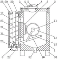
Fig. 1 is a schematic structural view of the present invention;
fig. 2 is a left side view of fig. 1 in accordance with the present invention;
fig. 3 is a top view of the present invention shown in fig. 1;
FIG. 4 is an enlarged view of the point A of FIG. 1 according to the present invention;
fig. 5 is an enlarged view of the point B in fig. 2 according to the present invention;
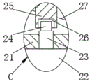
fig. 6 is an enlarged view of the point C in fig. 1 according to the present invention.
In the figure: 1. a box body; 2. a box cover; 3. a feed inlet; 4. an end cap; 5. a handle; 6. an annular groove; 7. an annular clamping strip; 8. a static jaw plate; 9. a first motor; 10. a first rotating shaft; 11. a square shaft; 12. a grinding wheel; 13. a square hole; 14. a support hole; 15. a support pin; 16. a connecting rod; 17. a bump; 18. installing a frame; 19. filtering with a screen; 20. a support bar; 21. stranding and cage; 22. a second motor; 23. a second rotating shaft; 24. a square block; 25. a main shaft; 26. a square groove; 27. a reamer; 28. covering the cage; 29. a limiting hole; 30. a discharge chute; 31. a feed chute; 32. a discharge hole; 33. and (3) a support leg.
Detailed Description
The technical solutions in the embodiments of the present invention will be described clearly and completely with reference to the accompanying drawings in the embodiments of the present invention, and it is obvious that the described embodiments are only some embodiments of the present invention, not all embodiments. Based on the embodiments in the present invention, all other embodiments obtained by a person skilled in the art without creative work belong to the protection scope of the present invention.
Referring to fig. 1-6, the present invention provides a technical solution: a goat feed grinder comprises a box body 1, the upper end of the box body 1 is connected with a box cover 2 through screws, a feed inlet 3 is formed in the box cover 2 and used for feeding feed, the upper end of the box cover 2 is connected with an end cover 4 in a contact mode, a handle 5 is welded at the upper end of the end cover 4, a static jaw plate 8 is welded on the inner wall of the left end of the box body 1, a first motor 9 is fixedly installed at the rear end of the box body 1, a first rotating shaft 10 is arranged at the front end of the first motor 9, the first rotating shaft 10 is sleeved in the box body 1 in a sliding mode, a square shaft 11 is welded at the front end of the first rotating shaft 10, a grinding wheel 12 is clamped on the outer side of the square shaft 11;
In order to fix the end cover 4 on the upper end of the box cover 2 and seal the feed port 3, in this embodiment, preferably, the lower end of the end cover 4 is provided with an annular clamping strip 7, the upper end of the box cover 2 is provided with an annular groove 6, and the annular clamping strip 7 is slidably connected in the annular groove 6.
In order to rotate the first rotating shaft 10 to rotate the crushing wheel 12 to crush the feed, in this embodiment, preferably, a square hole 13 is formed in the crushing wheel 12, and a square shaft 11 is clamped in the square hole 13.
In order to keep the mounting frame 18 stable, in this embodiment, preferably, the front end of the box body 1 is fixedly sleeved with the support rod 20, the right end of the mounting frame 18 is slidably sleeved with the support rod 20, there are two support rods 20, and the two support rods 20 are symmetrically distributed at the right end of the mounting frame 18.
In order to make the hank cage 21 carry out the transmission material loading to the fodder, in this embodiment, preferred, the upper end of second motor 22 is provided with second pivot 23, and sliding sleeve has second pivot 23 in the hank cage 21, and the upper end welding of second pivot 23 has square piece 24, and square piece 24's upper end joint has main shaft 25, and square groove 26 has been seted up to main shaft 25's lower extreme, and square piece 24 has been cup jointed in square groove 26, and main shaft 25 is provided with reamer 27.
In order to stabilize the rotation of the spindle 25, in the present embodiment, preferably, the upper end of the twisting cage 21 is connected to a cage cover 28 through a screw, a limiting hole 29 is formed in the cage cover 28, and the spindle 25 is rotatably sleeved in the limiting hole 29.
In order to stabilize the box 1, the discharging hole 32 can discharge, in this embodiment, preferably, the lower end of the box 1 is welded with four support legs 33, and the four support legs 33 are uniformly distributed at the lower end of the box 1.
The utility model discloses a theory of operation and use flow: when the feed grinder is used, feed enters from the feed inlet 3, a power supply is connected through an external plug, the first motor 9 is started, the first rotating shaft 10 rotates to drive the square shaft 11 to rotate, the square shaft 11 rotates to drive the crushing wheel 12 to rotate, the crushing wheel 12 rotates to be matched with the static jaw plate 8 to crush the feed, the crushing wheel 12 rotates to drive the support hole 14 to do eccentric motion, the support hole 14 does eccentric motion to drive the support pin 15 to do eccentric motion, the support pin 15 does eccentric motion to drive the connecting rod 16 to do up-and-down reciprocating motion, the projection 17 is driven to do up-and-down reciprocating motion, the mounting frame 18 is driven to deflect to generate vibration, the incompletely crushed feed at the upper end of the filter screen 19 slides into the stranding cage 21, meanwhile, the filter screen 19 cannot be blocked, the filtering efficiency is higher, the second motor 22 is started, the second rotating shaft 23 rotates to drive the square block 24 to rotate, the main shaft 25 rotates to, the feed is crushed again through the matching of the crushing wheel 12 and the static jaw plate 8 until the feed can be discharged from the discharge hole 32 through the filter screen 19, so that the feed can be crushed more thoroughly.
Although embodiments of the present invention have been shown and described, it will be appreciated by those skilled in the art that changes, modifications, substitutions and alterations can be made in these embodiments without departing from the principles and spirit of the invention, the scope of which is defined in the appended claims and their equivalents.
Claims (7)
1. The utility model provides a goat feed grinder, includes box (1), its characterized in that: the upper end of the box body (1) is connected with a box cover (2) through a screw, a feed inlet (3) is formed in the box cover (2), the upper end of the box cover (2) is connected with an end cover (4) in a contact manner, a handle (5) is welded at the upper end of the end cover (4), a static jaw plate (8) is welded on the inner wall of the left end of the box body (1), a first motor (9) is fixedly installed at the rear end of the box body (1), a first rotating shaft (10) is arranged at the front end of the first motor (9), the first rotating shaft (10) is sleeved in the box body (1) in a sliding manner, a square shaft (11) is welded at the front end of the first rotating shaft (10), and a crushing wheel (12) is clamped on the outer;
support hole (14) have been seted up to the front end of smashing wheel (12), it has cup jointed supporting pin (15) to slide in support hole (14), the front end welding of supporting pin (15) has connecting rod (16), the lower extreme of connecting rod (16) is provided with lug (17), installing frame (18) have been cup jointed in the outside slip of lug (17), be provided with filter screen (19) in installing frame (18), the left end fixed mounting of box (1) has stranding cage (21), the lower extreme fixed mounting of stranding cage (21) has second motor (22), feed chute (31) have been seted up to the left side upper end of box (1), blown down tank (30) have been seted up to the left side lower extreme of box (1), blown down hole (32) have been seted up to the lower extreme of box (1).
2. The goat feed grinder as claimed in claim 1, wherein: the lower extreme of end cover (4) is provided with annular card strip (7), ring channel (6) have been seted up to the upper end of case lid (2), sliding connection has annular card strip (7) in ring channel (6).
3. The goat feed grinder as claimed in claim 1, wherein: a square hole (13) is formed in the crushing wheel (12), and a square shaft (11) is connected in the square hole (13) in a clamping mode.
4. The goat feed grinder as claimed in claim 1, wherein: the front end of the box body (1) is fixedly sleeved with a supporting rod (20), the right end of the mounting frame (18) is slidably sleeved with the supporting rod (20), the number of the supporting rods (20) is two, and the two supporting rods (20) are symmetrically distributed at the right end of the mounting frame (18).
5. The goat feed grinder as claimed in claim 1, wherein: the upper end of second motor (22) is provided with second pivot (23), sliding sleeve has been connected second pivot (23) in hank cage (21), the upper end welding of second pivot (23) has square piece (24), the upper end joint of square piece (24) has main shaft (25), square groove (26) have been seted up to the lower extreme of main shaft (25), square piece (24) have been cup jointed in square groove (26), be provided with reamer (27) of main shaft (25).
6. The goat feed grinder as claimed in claim 1, wherein: the upper end of the stranding cage (21) is connected with a cage cover (28) through a screw, a limiting hole (29) is formed in the cage cover (28), and a main shaft (25) is rotatably sleeved in the limiting hole (29).
7. The goat feed grinder as claimed in claim 1, wherein: the lower extreme welding of box (1) has stabilizer blade (33), stabilizer blade (33) have four, four stabilizer blade (33) evenly distributed is at the lower extreme of box (1).
Priority Applications (1)
| Application Number | Priority Date | Filing Date | Title |
|---|---|---|---|
| CN202020113647.6U CN212309727U (en) | 2020-01-19 | 2020-01-19 | Goat feed grinder |
Applications Claiming Priority (1)
| Application Number | Priority Date | Filing Date | Title |
|---|---|---|---|
| CN202020113647.6U CN212309727U (en) | 2020-01-19 | 2020-01-19 | Goat feed grinder |
Publications (1)
| Publication Number | Publication Date |
|---|---|
| CN212309727U true CN212309727U (en) | 2021-01-08 |
Family
ID=74029842
Family Applications (1)
| Application Number | Title | Priority Date | Filing Date |
|---|---|---|---|
| CN202020113647.6U Expired - Fee Related CN212309727U (en) | 2020-01-19 | 2020-01-19 | Goat feed grinder |
Country Status (1)
| Country | Link |
|---|---|
| CN (1) | CN212309727U (en) |
-
2020
- 2020-01-19 CN CN202020113647.6U patent/CN212309727U/en not_active Expired - Fee Related
Similar Documents
| Publication | Publication Date | Title |
|---|---|---|
| CN111729721B (en) | Circulating fodder reducing mechanism | |
| CN213726939U (en) | Reducing mechanism is used in processing of chinese angelica raw and other materials | |
| CN210729725U (en) | Navel pastes production with chinese-medicinal material milling equipment | |
| CN214717187U (en) | Small-size fodder grinder | |
| CN112742583A (en) | Fodder reducing mechanism is used to sheep | |
| CN212309727U (en) | Goat feed grinder | |
| CN215655617U (en) | Blue tungsten oxide preparation is with multiple broken screening plant of raw materials | |
| CN208321043U (en) | A kind of feed grinder | |
| CN213376377U (en) | Feed additive grinds mixing arrangement | |
| CN209005858U (en) | One kind can sieve soil beveller | |
| CN219703514U (en) | Titanium piece grinder | |
| CN208975971U (en) | A kind of animal husbandry niblet grinding device | |
| CN208627109U (en) | One kind being suitable for gold ink grinding stirring deployment device | |
| CN113751169B (en) | Ultrafine grinder for efficiently processing feed | |
| CN213784274U (en) | Poultry fodder reducing mechanism | |
| CN216323146U (en) | Cylinder screening plant is used in organic fertilizer production | |
| CN213193997U (en) | Food raw material processing grinding device | |
| CN212263507U (en) | A kind of Chinese medicine crushing and grinding equipment | |
| CN204816800U (en) | Doublestage reducing mechanism | |
| CN213528961U (en) | Food processing is with grinding reducing mechanism | |
| CN211274859U (en) | Improved feed grinder | |
| CN209093544U (en) | Uniform feed stuff reducing device can be crushed | |
| CN220460926U (en) | Superfine calcium carbonate production grinder | |
| CN112495533A (en) | High-quality circular processing equipment for granulated feed | |
| CN215124231U (en) | Yak is bred and uses feed treatment equipment |
Legal Events
| Date | Code | Title | Description |
|---|---|---|---|
| GR01 | Patent grant | ||
| GR01 | Patent grant | ||
| CF01 | Termination of patent right due to non-payment of annual fee | ||
| CF01 | Termination of patent right due to non-payment of annual fee |
Granted publication date: 20210108 Termination date: 20220119 |