CN212319081U - A pipe connection device - Google Patents
A pipe connection device Download PDFInfo
- Publication number
- CN212319081U CN212319081U CN202020398558.0U CN202020398558U CN212319081U CN 212319081 U CN212319081 U CN 212319081U CN 202020398558 U CN202020398558 U CN 202020398558U CN 212319081 U CN212319081 U CN 212319081U
- Authority
- CN
- China
- Prior art keywords
- block
- piece
- engaging
- rotating
- rotating shaft
- Prior art date
- Legal status (The legal status is an assumption and is not a legal conclusion. Google has not performed a legal analysis and makes no representation as to the accuracy of the status listed.)
- Expired - Fee Related
Links
Images


Landscapes
- Mutual Connection Of Rods And Tubes (AREA)
Abstract
The utility model discloses a connecting device of pipeline, connecting device include the fastener of symmetric distribution, the one end of fastener is equipped with first connecting piece, and the other end is equipped with the second connecting piece, is equipped with the control on the second connecting piece, is equipped with the screw rod on the control, rotates on the screw rod and is equipped with the turning block, rotates on the turning block and is equipped with the block, and it has the body to call the block interior block of distribution, and the fastener includes the arc supporting shoe, and the both ends of arc supporting shoe all are equipped with first connecting block, are equipped with the block groove on the fastener, and the block groove is located the arc supporting shoe. The utility model discloses connecting device rotates the second connecting piece with the flange contact of two bodys, with two fastener suit on the flange, rotates the control, through the first connecting block of lug extrusion one side, with U type block on the first connecting block of opposite side, rotates the screw rod and locks, replaces traditional body connected mode, has reduced staff's intensity of labour, has improved work efficiency.
Description
Technical Field
The utility model relates to a connecting device specifically is a connecting device of pipeline.
Background
Need connect the body at the body in-process of laying, the common mode of body coupling among the prior art has: the flange connection is realized, and a plurality of screw rods need to be screwed in the flange connection process, so that the labor intensity of workers is high, and the efficiency is low; the pipe hoop is connected, and the pipe hoop lacks stability in the process of addition and is easy to fall off; welding, the cost is great, and staff's intensity is great, and the later stage is changed inconveniently.
SUMMERY OF THE UTILITY MODEL
An object of the utility model is to provide a connecting device of pipeline, with the flange contact of two bodys, with two fastener suit on the flange, rotate the second connecting piece, rotate the control, through the first connecting block of lug extrusion one side, with U type fastener block on the first connecting block of opposite side, rotate the screw rod and lock, replace traditional body connected mode, reduced staff's intensity of labour, improved work efficiency, easy operation is suitable for the practicality.
The purpose of the utility model can be realized by the following technical scheme:
the utility model provides a connecting device of pipeline, connecting device includes the fastener of symmetric distribution, the one end of fastener is equipped with first connecting piece, and the other end is equipped with the second connecting piece, is equipped with the control on the second connecting piece, is equipped with the screw rod on the control, rotates on the screw rod to be equipped with the turning block, rotates on the turning block to be equipped with the block, and the block has the body in the fastener of weighing distribution.
The clamping piece comprises an arc-shaped supporting block, first connecting blocks are arranged at two ends of the arc-shaped supporting block, a clamping groove is formed in the clamping piece and located in the arc-shaped supporting block, first inclined contact surfaces which are symmetrically distributed are arranged in the clamping groove, and a connecting hole is formed in the first connecting block.
The first connecting pieces comprise first connecting plates which are symmetrically distributed, and first rotating shafts which are symmetrically distributed are arranged between the first connecting plates.
The second connecting piece comprises symmetrically distributed second connecting plates, a second rotating shaft is arranged between the second connecting plates, a third rotating shaft is arranged between the second connecting plates, and symmetrically distributed limiting columns are arranged on the third rotating shaft.
The control piece comprises a convex block, a first rotating connecting hole is formed in the convex block, a connecting rod is arranged on the convex block, one end of the connecting rod is fixedly connected with the convex block, a handle is arranged at the other end of the connecting rod, a supporting column is arranged on the handle, and a through hole is formed in the supporting column.
The turning block comprises a connecting shaft, wherein fourth rotating shafts are arranged at two ends of the connecting shaft, and threaded holes are formed in the connecting shaft.
The clamping block comprises a U-shaped clamping block, a second connecting block is arranged on the U-shaped clamping block, and a second rotating connecting hole is formed in the second connecting block.
The pipe body comprises a pipe main body, a flange is arranged at one end of the pipe main body, and a second inclined contact surface is arranged at the joint of the flange and the pipe main body.
Furthermore, the first connecting piece is respectively connected with the connecting holes of the two clamping pieces in a rotating mode through a first rotating shaft.
Furthermore, the second connecting piece is rotatably connected with the connecting hole on one side through a second rotating shaft, and the first connecting piece and the second connecting piece are respectively positioned on two sides of the clamping piece.
Further, the control piece is rotatably connected with the third rotating shaft through the first rotating connecting hole.
Further, the screw rod penetrates through the through hole to be matched with the control piece.
Furthermore, the rotating block is rotatably connected with the second rotating connecting hole through a fourth rotating shaft.
Furthermore, the flange is located in the clamping groove, and the first inclined contact surface is in contact extrusion with the second inclined contact surface.
The utility model has the advantages that:
1. the utility model discloses the flange contact of two bodys is with two fastener suits on the flange to the connecting device, rotates the second connecting piece, at the rotation control piece, extrudees the first connecting block of one side through the lug, blocks U type fastener on the first connecting block of opposite side, rotates the screw rod and locks, replaces traditional body connected mode, has reduced staff's intensity of labour, has improved work efficiency;
2. the utility model discloses it is convenient that the body is changed in the connecting device installation, and simple structure is suitable for the practicality.
Drawings
The present invention will be further described with reference to the accompanying drawings.
FIG. 1 is a schematic view of the structure of the connection device of the present invention;
FIG. 2 is a schematic view of the engaging member of the present invention;
fig. 3 is a schematic structural view of a first connecting member of the present invention;
fig. 4 is a schematic structural view of a second connecting member of the present invention;
FIG. 5 is a schematic view of the control member of the present invention;
FIG. 6 is a schematic view of the structure of the rotary block of the present invention;
FIG. 7 is a schematic view of the structure of the engaging block of the present invention;
fig. 8 is a schematic view of the structure of the tube body of the present invention.
Detailed Description
The technical solutions in the embodiments of the present invention will be described clearly and completely with reference to the accompanying drawings in the embodiments of the present invention, and it is obvious that the described embodiments are only some embodiments of the present invention, not all embodiments. Based on the embodiments of the present invention, all other embodiments obtained by a person of ordinary skill in the art without creative efforts belong to the protection scope of the present invention.
The utility model provides a connecting device of pipeline, connecting device includes the fastener 1 of symmetric distribution, as shown in fig. 1, the one end of fastener 1 is equipped with first connecting piece 2, and the other end is equipped with second connecting piece 3, is equipped with control 4 on the second connecting piece 3, is equipped with screw rod 5 on the control 4, rotates on the screw rod 5 and is equipped with turning block 6, rotates on turning block 6 and is equipped with block 7, calls the interior joint of fastener 1 that distributes and has a body 8.
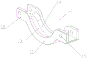
The engaging member 1 includes an arc-shaped supporting block 11, as shown in fig. 2, first connecting blocks 12 are disposed at two ends of the arc-shaped supporting block 11, an engaging groove 13 is disposed on the engaging member 1, the engaging groove 13 is located in the arc-shaped supporting block 11, first inclined contact surfaces 14 symmetrically distributed are disposed in the engaging groove 13, and a connecting hole 15 is disposed on the first connecting block 12.
The first connecting member 2 includes first connecting plates 21 symmetrically distributed, and as shown in fig. 3, first rotating shafts 22 symmetrically distributed are disposed between the first connecting plates 21.
The second connecting member 3 includes second connecting plates 31 symmetrically distributed, as shown in fig. 4, a second rotating shaft 32 is disposed between the second connecting plates 31, a third rotating shaft 33 is disposed between the second connecting plates 31, and limiting posts 34 symmetrically distributed are disposed on the third rotating shaft 33.
The control member 4 includes a protrusion 41, as shown in fig. 5, a first rotation connection hole 42 is formed on the protrusion 41, a connection rod 43 is arranged on the protrusion 41, one end of the connection rod 43 is fixedly connected with the protrusion 41, a handle 44 is arranged at the other end of the connection rod 43, a support pillar 45 is arranged on the handle 44, and a through hole 46 is formed on the support pillar 45.
The first connecting piece 2 is respectively connected with the connecting holes 15 of the two clamping pieces 1 in a rotating way through the first rotating shaft 22, the second connecting piece 3 is connected with the connecting hole 15 of one side in a rotating way through the second rotating shaft 32, the first connecting piece 2 and the second connecting piece 3 are respectively positioned at two sides of the clamping pieces 1, and the control piece 4 is connected with the third rotating shaft 33 in a rotating way through the first rotating connecting hole 42.
The rotating block 6 comprises a connecting shaft 61, as shown in fig. 6, a fourth rotating shaft 63 is arranged at each end of the connecting shaft 61, a threaded hole 62 is formed in the connecting shaft 61, and the screw 5 penetrates through the through hole 46 to be matched with the control member 4.
The engaging block 7 includes a U-shaped engaging block 71, and as shown in fig. 7, a second connecting block 72 is provided on the U-shaped engaging block 71, and a second rotation connecting hole 73 is provided on the second connecting block 72.
The rotation block 6 is rotatably coupled to the second rotation coupling hole 73 through the fourth rotation shaft 63.
The pipe body 8 includes a pipe body 81, and as shown in fig. 8, a flange 82 is provided at one end of the pipe body 81, and a second inclined contact surface 83 is provided at a connection portion of the flange 82 and the pipe body 81.
The flange 82 is positioned in the engagement groove 13, and the first inclined contact surface 14 is pressed against the second inclined contact surface 83.
During the use, with the flange 82 contact of two bodys, with two fastener 1 suits on flange 82, rotate second connecting piece 3, at rotation control 4, extrude the first connecting block 12 of one side through lug 41, with U type block 71 block on the first connecting block 12 of opposite side, rotate screw rod 5 and lock, replace traditional body connected mode, reduced staff's intensity of labour, improved work efficiency, easy operation is suitable for the practicality.
In the description herein, references to the description of "one embodiment," "an example," "a specific example," etc., mean that a particular feature, structure, material, or characteristic described in connection with the embodiment or example is included in at least one embodiment or example of the invention. In this specification, the schematic representations of the terms used above do not necessarily refer to the same embodiment or example. Furthermore, the particular features, structures, materials, or characteristics described may be combined in any suitable manner in any one or more embodiments or examples.
The foregoing shows and describes the general principles, essential features, and advantages of the invention. It will be understood by those skilled in the art that the present invention is not limited to the above embodiments, and that the foregoing embodiments and descriptions are provided only to illustrate the principles of the present invention without departing from the spirit and scope of the present invention.
Claims (7)
Priority Applications (1)
| Application Number | Priority Date | Filing Date | Title |
|---|---|---|---|
| CN202020398558.0U CN212319081U (en) | 2020-03-25 | 2020-03-25 | A pipe connection device |
Applications Claiming Priority (1)
| Application Number | Priority Date | Filing Date | Title |
|---|---|---|---|
| CN202020398558.0U CN212319081U (en) | 2020-03-25 | 2020-03-25 | A pipe connection device |
Publications (1)
| Publication Number | Publication Date |
|---|---|
| CN212319081U true CN212319081U (en) | 2021-01-08 |
Family
ID=74017678
Family Applications (1)
| Application Number | Title | Priority Date | Filing Date |
|---|---|---|---|
| CN202020398558.0U Expired - Fee Related CN212319081U (en) | 2020-03-25 | 2020-03-25 | A pipe connection device |
Country Status (1)
| Country | Link |
|---|---|
| CN (1) | CN212319081U (en) |
-
2020
- 2020-03-25 CN CN202020398558.0U patent/CN212319081U/en not_active Expired - Fee Related
Similar Documents
| Publication | Publication Date | Title |
|---|---|---|
| CN212319081U (en) | A pipe connection device | |
| CN219242891U (en) | A heavy-duty twin-screw tube bundle for easy installation | |
| CN213512493U (en) | A high-stability spinning oil pipe joint that is easy to connect | |
| CN211171952U (en) | A composite concrete pipe pile that can be quickly spliced | |
| CN207700391U (en) | A kind of steel construction of fast assembling-disassembling | |
| CN107419853B (en) | A kind of reinforced steel bar straight thread coupling sleeve with realizing middle limiting | |
| CN201028024Y (en) | Open gate valve | |
| CN214815932U (en) | Cutting of assembled steel construction thick plate and groove mounting structure for steel construction building | |
| CN213572258U (en) | Road drainage structure | |
| CN212718372U (en) | PPR is location structure for pipe connection spare | |
| CN212715381U (en) | Building steel structure connecting piece | |
| CN211232030U (en) | Sealing connection structure for heat preservation pipe elbow | |
| CN214034714U (en) | A special fastener for rotatable wall-connecting parts | |
| CN212672630U (en) | High-pressure split flange joint for metal sealing | |
| CN216618876U (en) | Novel rubber circle convenient to connect | |
| CN210273400U (en) | Connecting assembly for cable pipe convenient to use | |
| CN210557198U (en) | A clamping device for building brick | |
| CN211080783U (en) | Detachable threaded steel bar connecting sleeve | |
| CN210857747U (en) | A removable threaded steel bar connecting sleeve | |
| CN214738719U (en) | Steel component for archaize building convenient to connect | |
| CN211173144U (en) | Building concrete shakeouts device | |
| CN221346334U (en) | Waterproof coiled material fixing ring | |
| CN217924451U (en) | Grouting sleeve fastening and connecting tool for assembly type building | |
| CN218983722U (en) | Pressing device of steel bar truss machine | |
| CN221823380U (en) | A large diameter concrete cylindrical formwork reinforcement structure |
Legal Events
| Date | Code | Title | Description |
|---|---|---|---|
| GR01 | Patent grant | ||
| GR01 | Patent grant | ||
| CF01 | Termination of patent right due to non-payment of annual fee | ||
| CF01 | Termination of patent right due to non-payment of annual fee |
Granted publication date: 20210108 |