Background
Along with the improvement of living standard, people pay more attention to the comfort of working and living environment, and the demand for the air conditioner is also greatly improved.
The shell of the air conditioner comprises an outer cover and a base which are connected with each other, the base is connected with the wall surface of the air conditioner after the air conditioner is installed, and when the air conditioner needs to be overhauled, the outer cover can be directly disassembled to carry out overhauling operation without disassembling the whole machine. In the prior art, the outer cover is directly covered outside the base, the back edge of the outer cover is not supported, if the installation surface is uneven, the edge of the outer cover cannot be attached to the installation surface, and the edge of the outer cover deforms under the stress, so that the shell is damaged.
SUMMERY OF THE UTILITY MODEL
The utility model provides a problem how protect dustcoat rear side edge, prevent that the dustcoat from warping and damaging.
In order to solve the problem, the utility model provides an air conditioner shell, including base and dustcoat, the base sets up the rear side of dustcoat, the base has all around to keep off the edge, keep off the edge have bellied step edge all around, keep off along with the step is along forming the stair structure, the rear side edge of dustcoat is to extending all around to form the lid edge, the extension edge on lid edge extends to the rear side and forms annular bounding wall, the lid edge with keep off along offsetting, the extension end of bounding wall with the step is along offsetting, just the bounding wall encircles keep off the outside on edge.
Compared with the prior art, the utility model discloses an air conditioner shell has improved the structure of dustcoat and base, and the rear portion of base has outside extension's step edge, and when dustcoat and base assembled, the lid of dustcoat was followed and is kept off along offsetting, and the extension end of bounding wall offsets along the step, has injectd the relative position of dustcoat with the base, and the location improves the installation effectiveness when being convenient for assemble, and the step is followed and is played the support guard action to the bounding wall, prevents that the dustcoat from warping and damaging.
Optionally, an outer side wall surface of the enclosing plate is a third side wall, an outer side wall surface of the step edge is a second side wall, and the second side wall is flush with the third side wall.
The relative position that inject bounding wall and step along, fix a position fast when the dustcoat installation of being convenient for, the outside wall face of bounding wall flushes with the outside wall face on step edge, can strengthen air conditioner shell's an organic whole sense, promotes the aesthetic property.
Optionally, a groove is formed in the third side wall, and the groove is formed in the extending end of the enclosing plate.
Set up the recess at the lateral wall face that the bounding wall extends the end, when the dustcoat needs to be dismantled, operator's finger or instrument can get into the recess, apply the effort to the bounding wall, realize the separation of dustcoat and base, have improved the convenience of tearing open the machine, prevent to dismantle in-process shell damage.
Optionally, the width of the groove is between 0.5mm and 2mm, and the depression depth of the groove is between 0.5mm and 2 mm.
The width and the depth of the groove are controlled, and meanwhile, the convenience and the attractive appearance of the air conditioner shell are guaranteed.
Optionally, an inner side wall surface of the enclosing plate is a fourth side wall, an outer side wall surface of the blocking edge is a first side wall, and a distance between the first side wall and the fourth side wall is between 0.5mm and 2 mm.
The bounding wall has the clearance with keeping off between the edge, when can avoiding dustcoat and base assembly, keeps off along producing the interference to the bounding wall, the dustcoat location assembly of being convenient for, and the clearance should not be too big, makes to keep off along can supporting the bounding wall, avoids the bounding wall to warp the damage.
Optionally, the shroud has an extension length of between 3mm and 12 mm.
The extension length of the coaming is controlled, so that the coaming has the limiting effect on the outer cover, meanwhile, the interference is reduced, and the assembly of the outer cover is convenient.
Optionally, the thickness of the blocking edge is between 5mm and 15mm, the thickness c of the step edge is between 2mm and 4mm, and the ratio of the thickness of the step edge to the thickness of the blocking edge is between 1/3 and 1/5.
The thickness that the limit was kept off along with the step to and the thickness ratio that the limit was kept off along with the step along, guarantee to keep off along all having certain structural strength with the step along, keep off in addition along having certain difference with the thickness that the step was followed, guarantee to keep off along can playing limiting displacement to the dustcoat.
Optionally, the step edge is provided with ribs on the rear side.
The rib can strengthen the structural strength that the step was followed, prevents that step edge and base from warping and damaging.
Optionally, the cover edge is provided with at least one first screw hole, and the blocking edge is provided with a second screw hole matched with the first screw hole.
The cover edge and the blocking edge are provided with screw holes, so that the outer cover and the base can be reliably connected through screws.
The utility model also provides an air conditioner, including foretell air conditioner shell. Compared with the prior art, the air conditioner has the same beneficial effects as the air conditioner shell, and the details are not repeated.
Detailed Description
In the description of the present invention, it should be noted that terms such as "upper", "lower", "front", "rear", "left", "right", etc. in the embodiments indicate terms of orientation, and are only used for simplifying the description of positional relationships based on the drawings of the specification, and do not represent that the elements, devices, etc. indicated must be operated according to the specific orientation and defined operation and method, configuration in the specification, and such terms of orientation do not constitute limitations of the present invention.
The utility model discloses a be provided with coordinate system XYZ in the drawing of embodiment, wherein the place ahead is represented to the forward of X axle, and the back is represented to the reverse of X axle, and the top is represented to the forward of Y axle, and the below is represented to the reverse of Y axle, and the right-hand is represented to the forward of Z axle, and the left is represented to the reverse of Z axle.
The embodiments of the present invention refer to "inside" and "outside", which means that the center near the housing is the inside and the center far away from the housing is the outside, relative to a housing structure.
In the description of the present invention, it should be noted that the terms "first" and "second" mentioned in the embodiments of the present invention are only used for descriptive purposes and are not to be construed as indicating or implying relative importance or implicitly indicating the number of indicated technical features. Thus, a feature defined as "first" or "second" may explicitly or implicitly include one or more of that feature.
In order to make the aforementioned objects, features and advantages of the present invention more comprehensible, embodiments accompanied with figures are described in detail below.
An embodiment of the utility model provides an air conditioner, it can install indoor or inside the vehicle for adjust ambient temperature, improve human experience. The air conditioner comprises an air conditioner shell, wherein a cavity is formed in the air conditioner shell and used for installing components such as an evaporator, a fan and an electric control box, the components installed in the shell are protected by the air conditioner shell, and the attractiveness of the whole air conditioner can be improved.
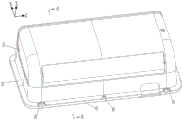
Referring to fig. 1 to 8, the air conditioner casing includes a base 1 and an outer cover 2 connected to each other, and the base 1 and the outer cover 2 are detachably and fixedly connected by a snap structure and/or a screw. The housing 2 includes a front panel (in the forward direction of the X-axis in the figure) and side panels surrounding the front panel, the rear side (in the reverse direction of the X-axis in the figure) of the housing 2 is opened, the housing 2 has a receiving cavity for providing a receiving space for the base 1 and components fixed on the base 1, and the base 1 is installed on the opening side of the housing 2. When the air conditioner is installed, the base 1 is connected with an indoor installation surface, when the internal parts of the air conditioner are required to be overhauled, the shell can be directly disassembled without disassembling the whole machine, and the outer cover 2 is separated from the base 1 to carry out internal overhaul.
As shown in fig. 2 to 4, the base 1 has a blocking edge 3 around the base, and the blocking edge 3 is disposed at the rear of the base 1 and is used for abutting against the outer cover 2 to define the assembling position of the outer cover 2. The periphery of the blocking edge 3 is provided with a step edge 4 protruding outwards, the thickness of the step edge 4 is smaller than that of the blocking edge 3, the step edge is arranged at the rear part of the blocking edge 3, and the blocking edge 3 and the step edge 4 form a step structure. The step 4 is used to abut against the edge of the outer cover 2 for support.
The rear side edge of the outer cover 2 extends towards the periphery to form a cover edge 5, the extending edge of the cover edge 5 extends towards the rear side to form an annular coaming 6, the cover edge 5 is used for abutting against the base 1 to limit the positions of the outer cover 2 and the base 1 in the front-rear direction, and the coaming 6 is used for surrounding the side face of the base 1 to limit the positions of the outer cover 2 and the base 1 in the up-down left-right direction.
Combine fig. 5 and fig. 6 to show, when base 1 and dustcoat 2 assemble, the lid offsets along 5 and fender edge 3, and bounding wall 6 encircles in the outside of keeping off along 3, and bounding wall 6 will keep off along 3 wraps up with the lid along 5, plays limiting displacement, guarantees that dustcoat 2 assembles to target in place, and the structure that the while bounding wall 6 encircles fender edge 3 can shelter from the lid along 5 and keep off along 3 assembly gap, promotes air conditioner shell's pleasing to the eye degree. The extension end of bounding wall 6 offsets along 4 with the step, and the step plays the support guard action to bounding wall 6 along 4, and the step can not take place deformation during 6 atresss of bounding wall along the front surface of 4 and the laminating of the extension end terminal surface of bounding wall 6, avoids shell dismouting in-process dustcoat 2 to damage. In addition, the coaming 6 offsets with the step along 4, the lid offsets with keeping off along 3 along 5 can all inject dustcoat 2 and base 1's assembly position, and the quick location improves the installation effectiveness when the dustcoat 2 of being convenient for assembles.
Further, the back surface (rear side surface) of the step edge 4 is provided with ribs for reinforcing the structural strength of the step edge 4. The shape of the ribs is not limited, and the ribs can be straight ribs extending up and down, straight ribs extending left and right, curved ribs, square ribs, round ribs and the like.
Further, the cover edge 5 is provided with at least one first screw hole 8, the blocking edge 3 is provided with at least one second screw hole 9, the number of the first screw holes 8 is the same as that of the second screw holes 9, and the positions of the first screw holes 8 and the second screw holes 9 are aligned. The cover edge 5 and the blocking edge 3 can be fixedly connected through screws, the screw connection is reliable, and the outer cover 2 and the base 1 are prevented from being separated or dislocated.
The outer wall surface defining the blocking edge 3 is the first side wall 31, the outer wall surface of the step edge 4 is the second side wall 41, the outer wall surface of the apron 6 is the third side wall 61, and the inner wall surface of the apron 6 is the fourth side wall 62. With reference to fig. 7 and 8, the dimensions of the coaming 6, the blocking edge 3 and the step edge 4 are limited, and the requirements of convenience in assembly, accuracy in positioning and difficulty in deformation are met.
Specifically, the extension a of the shroud 6 in this embodiment is 8 mm. The extension length a of bounding wall 6 should not be too short, otherwise can't play limiting displacement, and dustcoat 2 and base 1 throw off easily, and the extension length a of bounding wall 6 should not too big yet, otherwise can produce when the assembly of dustcoat 2 and interfere, is unfavorable for the shell dismouting. Thus, in other embodiments, the control fence 6 extends for a length a between 3mm and 12 mm.
In the embodiment, the thickness b of the blocking edge 3 is 10mm, the thickness c of the step edge 4 is 2mm, and certain structural strength of the blocking edge 3 and the step edge 4 is guaranteed. In other embodiments, the thickness b of the blocking edge 3 is between 5mm and 15mm, the thickness c of the step edge 4 is between 2mm and 4mm, the ratio of the thickness c of the step edge 4 to the thickness b of the blocking edge 3 is between 1/3 and 1/5, and a certain difference exists between the thicknesses of the blocking edge 3 and the step edge 4, so that the blocking edge 3 can limit the position of the outer cover.
In addition, the difference value between the thickness b of the blocking edge 3 and the thickness c of the step edge 4 is equal to the extension length a of the enclosing plate 6, so that the cover edge 5 abuts against the blocking edge 3, and the enclosing plate 6 abuts against the step edge 4, a stable supporting and protecting structure is formed, and the edge of the outer cover 2 is prevented from being deformed and damaged.
Furthermore, a gap is formed between the enclosing plate 6 and the blocking edge 3, so that the interference of the blocking edge 3 on the enclosing plate 6 can be avoided when the outer cover 2 is assembled with the base 1, and the positioning and assembly of the outer cover 2 are facilitated. The gap should not be too large, otherwise the baffle edge 3 cannot support the coaming 6, the coaming 6 may be deformed and damaged, and the distance d between the first side wall 31 of the baffle edge 3 and the fourth side wall 62 of the coaming 6 is controlled to be between 0.5mm and 2 mm.
The relative position of the enclosing plate 6 and the step edge 4 is defined, and after the outer cover 2 is assembled with the base 1, the third side wall 61 of the enclosing plate 6 is flush with the second side wall 41 of the step edge 4, so that the outer cover 2 can be quickly positioned when being installed. And the outer side wall surface of the coaming 6 is flush with the outer side wall surface of the step edge 4, so that the integral feeling of the air conditioner shell can be enhanced, and the attractiveness is improved.
Referring to fig. 6, the third side wall 61 of the shroud 6 is provided with a groove 7, and the groove 7 is located at the extending end of the shroud 6. When the outer cover 2 needs to be disassembled, fingers or tools of an operator can enter the groove 7 and apply acting force to the coaming 6 from the position of the groove 7, so that the outer cover 2 is separated from the base 1, and the convenience of disassembling the machine can be improved by arranging the groove 7. In addition, the arrangement of the groove 7 can avoid the outer cover 2 from being extruded when the machine is disassembled, and the shell is prevented from being damaged in the disassembling process.
As shown in fig. 8, the size of the groove 7 is limited, so that an operator can conveniently insert fingers or tools into the groove 7 without damaging the appearance of the shell, and the requirements of practicability and aesthetic property are met. In this embodiment, the width e of the groove 7 is 1mm, and the recess depth f of the groove 7 is 1 mm.
In other embodiments, the width e of the groove 7 is between 0.5mm and 2mm, and the depression depth f of the groove 7 is between 0.5mm and 2 mm.
The air conditioner that above-mentioned embodiment provided has novel air conditioner casing, the structure of dustcoat 2 and base 1 has been improved, base 1 has to keep off along 3 and step along 4, dustcoat 2 has to cover along 5 and bounding wall 6, when dustcoat 2 assembles with base 1, the lid is followed 5 and is kept off along 3 offsets, bounding wall 6 surrounds keeping off along 3 the outside, form limit structure, the extension end and the step of bounding wall 6 offset along 4, realize quick location, the assembly of the dustcoat 2 of being convenient for, the step plays the support guard action to the edge of dustcoat 2 along 4, effectively prevent that dustcoat 2 from deforming the damage, and has very high practical value.
Although the present invention is disclosed above, the present invention is not limited thereto. Various changes and modifications may be effected therein by one of ordinary skill in the pertinent art without departing from the scope or spirit of the present invention, and the scope of the present invention is defined by the appended claims.